Sealey SNA98 User manual

INSTRUCTIONS FOR:
NIBBLER CUTTING TOOL
Model No: SNA98
Thank you for purchasing a Sealey product. Manufactured to a high
standard this product will, if used according to these instructions and
properly maintained, give you years of trouble free performance.
IMPORTANT: PLEASE READ THESE INSTRUCTIONS CAREFULLY. NOTE THE SAFE
OPERATIONAL REQUIREMENTS, WARNINGS AND CAUTIONS. USE THIS PRODUCT
CORRECTLY AND WITH CARE FOR THE PURPOSE FOR WHICH IT IS INTENDED.
FAILURE TO DO SO MAY CAUSE DAMAGE OR PERSONAL INJURY, AND WILL
VALIDATE THE WARRANTY. PLEASE KEEP INSTRUCTIONS SAFE FOR FUTURE USE.
pWARNING! remove the cutter from the drill before servicing or performing any maintenance.
3Maintain cutter in good condition (use authorised service agent). Replace/repair damaged
parts. Use recommended parts, alternative parts are dangerous & will invalidate the warranty.
3Keep cutter clean for best and safest performance and check regularly moving parts.
3Keep tool bits clean and sharp for best and safest performance. Follow instructions for
lubrication and changing accessories.
3Remove chuck key from the drill before turning the cutting tool on.
3Ensure there are no flammable or combustible materials near the work area.
3Wear approved safety eye protection (standard spectacles are not adequate).
3Remove ill fitting clothes, ties, watches, rings, and other loose jewellery, and contain long hair.
3Locate cutter in a clean, tidy working area for its function, and ensure these is good lighting.
3Maintain correct balance and footing. Ensure the floor is not slippery and wear non slip shoes.
3Keep children and unauthorised persons away from the working area.
3Secure non stable work piece with a clamp, vice or other adequate holding device.
3Start drill before cutting commences, keep drill on until cutter is fully
removed from work piece.
3Avoid unintentional starting.
7DO NOT hold the workpiece by hand. Use clamps
or a vice (not included)
7DO NOT force the cutter to achieve a task it was not
designed to perform.
7DO NOT allow untrained persons to operate the cutter.
7DO NOT get cutter wet or use in damp or wet locations
or areas where there is condensation.
7DO NOT operate the cutter if damaged, or there
are parts missing.
7DO NOT exceed the rated capacity of the cutter.
7DO NOT use cutter where there is flammable liquids,
solids or gases.
7DO NOT leave the cutter operating whilst unattended.
7DO NOT use cutter if tired, under influence of alcohol, drugs or intoxicating medication.
3When not in use switch drill off and remove the cutter and store in a safe, dry, child proof area.
3. OPERATING INSTRUCTIONS
5. PARTS LIST
2. APPLICATION & SPECIFICATIONS
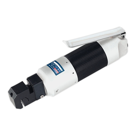
lThe SNA98 will cut sheet material, corrugated and rounded tubular sections etc in straight lines
and curves with radius as small as 12mm (1/2).
lThe indexable cutting head will adjust for different applications through 360Oquickly and without
dismantling the unit.
lThe tool will cut cleanly without distortion thus alleviate jagged edges.
Specifications
Power Source Any power drill, electric or air, with keyed chuck of 8mm (5/16)
capacity with speed range 1,500 to 3,000RPM.
Cut Width 4mm
Max recommended gauge Mild steel 1.6mm (16 S.W.G.)
Brass, Aluminium. Plastic 2.00mm (14 S.W.G.)
Stainless steel max 1.0mm (20 S.W.G.).
We recommend a separate punch be kept specifically for this
material as the extra wear caused by this hard steel can
prematurely affect the cutters performance when
used on other materials.
Before fitting cutter to the drill ensure the drill is switched off and unplugged from the power supply.
3.1. Insert the cutter drive shaft into the drill chuck and check to ensure the chuck jaws do not rub
on the body of the cutter and secure.
3.2. Select the desired position of the die (3) by slackening the die screw (5). with the provided
3mm hex key. Use a soft toothed wrench to turn the die and securely re-lock the screw.
3.3. Ensure your work piece does not exceed the specifications listed in chapter 2.
3.4. Apply a smear of oil to the tool cutting edge and along the work piece cutting line.
Note: This is particularly important when cutting aluminium.
3.5. Wear safety goggles and ensure all safety requirements of chapter 1 are followed.
3.6. Connect the drill to the power supply and switch on.
3.7. Bring the cutter to the work piece whilst in motion.
DO NOT start the cutter whilst held against the work piece.
3.8. Hold the drill and handle of the cutter firmly as you proceed with the cutting process.
DO NOT force the cutter.
3.9. When you wish to stop cutting leave the drill running whilst the cutter is removed from the
work piece. DO NOT stop the cutter whilst engaged with the work piece.
4. MAINTENANCE
When the cutting edges of the punch (2) and die (3) show signs of wear, both parts must
be renewed together as follows:
4.1. Slacken die screw (4) and withdraw the die.
4.2. Remove circlip (9) and end cap (8). Circlip may be carefully hooked out with a small
screw driver
4.3. Slacken punch location block screw (6) and withdraw the punch.
4.4. With punch location block (5) in position in the body (1), make sure the drive transfer bearing
(13) is located on the drive shaft pin (14) and that this bearing is in turn located correctly
in the channel of the punch location block (5).
4.5. Insert punch through die aperture in body, through punch location block into bronze bush (12).
Reverse procedure but make sure that the punch holding screw point locates into dimple
of punch to ensure correct operation, then lock screw and tighten locknut.
4.6. Re-pack with general purpose bearing grease.
No Part Description
1. SNA98/01 Body
2. SNA98/02 Punch
3. SNA98/03 Die
4. SNA98/04 Conical die screw 6mm
5. SNA98/05 Punch location block
6. SNA98/06 Punch screw
7. SNA98/07 Lock nut
8. SNA98/08 End cap
9. SNA98/09 Circlip
10. SNA98/10 Handle
11. SNA98/11 Plastic grip
12. SNA98/12 Bush
13. SNA98/13 Drive transfer bearing
14. SNA98/14 Drive pin
15. SNA98/15 Bearing
16. SNA98/16 Drive shaft
Sealey Group,
Bury St. Edmunds,
Suffolk.
01284 757500
01284 703534
E-mail:
sales@sealey.co.uk
SNA98 - tu - 110698
NOTE: It is our policy to continually improve products and as such we reserve the right to alter
data, specifications and component parts without prior notice.
IMPORTANT: No responsibility is accepted for incorrect use of this equipment
WARRANTY: Guarantee is 12 months from purchase date. Proof of purchase will be required
for any claim.
INFORMATION: Please call us for a copy of our latest catalogue.
Original Date: 110698
Issue Date:
Version No: 0
Date Modified: N/A
1. SAFETY INSTRUCTIONS
SNA98 - tu - 110698
Other Sealey Tools manuals

Sealey
Sealey VSE4786 User manual

Sealey
Sealey STW298 User manual

Sealey
Sealey POWER PRODUCTS SA811 User manual

Sealey
Sealey VS911.V2 User manual

Sealey
Sealey SA85 User manual

Sealey
Sealey VS2386 User manual

Sealey
Sealey CPG8V User manual

Sealey
Sealey VSE4778.V2 User manual

Sealey
Sealey RWH15.V3 User manual

Sealey
Sealey GSA11.V2 User manual

Sealey
Sealey AK2952 User manual

Sealey
Sealey SM94.V3 User manual

Sealey
Sealey AK505 User manual

Sealey
Sealey VS2049 User manual

Sealey
Sealey AUTO SERVICE VS720 User manual

Sealey
Sealey CP20VGT3 User manual

Sealey
Sealey CPG18V User manual

Sealey
Sealey Auto Service VS392 User manual

Sealey
Sealey RE91/05.V2 User manual

Sealey
Sealey VS2055.V4 User manual