Sealey CP20VGRG User manual

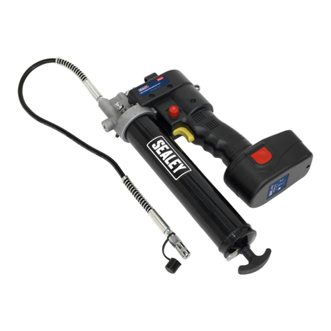
20V SV20 SERIES CORDLESS GREASE GUN-
BODY ONLY
MODEL NO: CP20VGRG
Thank you for purchasing a Sealey product. Manufactured to a high standard, this product will, if used according to these instructions,
and properly maintained, give you years of trouble free performance.
IMPORTANT: PLEASE READ THESE INSTRUCTIONS CAREFULLY. NOTE THE SAFE OPERATIONAL REQUIREMENTS, WARNINGS & CAUTIONS. USE
THE PRODUCT CORRECTLY AND WITH CARE FOR THE PURPOSE FOR WHICH IT IS INTENDED. FAILURE TO DO SO MAY CAUSE DAMAGE AND/OR
PERSONAL INJURYAND WILL INVALIDATE THE WARRANTY. KEEP THESE INSTRUCTIONS SAFE FOR FUTURE USE.
Refer to
instruction
manual
CP20VGRG Issue:1 06/10/22
Original Language Version
© Jack Sealey Limited
Wear eye
protection
1. INTRODUCTION
9Maintain the grease gun and battery in good condition. Check moving parts alignment on a regular basis.
9Replace or repair damaged parts. Use an authorised service agent and recommended parts only. Unauthorised parts may be
dangerous and will invalidate the warranty.
9Ensure the grease gun is switched o before installing the battery pack.
9Ensure battery pack is correctly inserted into the drill handle and latched in place before attempting to switch on the grease gun.
9Keep the grease gun and charger clean for best and safest performance.
9Remove ill tting clothing. Remove ties, watches, rings and other loose jewellery and contain long hair.
9Avoid unintentional starting.
9Wear approved safety eye protection (standard spectacles are not adequate).
9Maintain correct balance and footing. Ensure the floor is not slippery and wear non-skid shoes.
9Wear appropriate protective clothing. When handling lubricants refer to manufacturer’s instructions and conform to local regulations.
9Be aware that this grease gun does not need to be plugged into the mains power.
9Keep the switch in the off position until the grease gun is required for use.
9Keep children and unauthorised persons away from the working area.
8DO NOT use the grease gun where there are ammable liquids, solids or gases, such as paint solvents, etc.
8DO NOT allow children to operate the grease gun.
8DO NOT allow unauthorised persons to operate the gun.
8DO NOT operate the grease gun if any parts are missing as this may cause failure and/or personal injury.
8DO NOT hold unsecured work piece in your hand.
8WARNING! Disengage the grease gun from the battery before changing accessories, servicing or performing and maintenance.
9Maintain gun in good condition (use an authorised service agent).
9Replace or repair damaged parts. Use recommended parts only. Unauthorised parts may be dangerous and will invalidate the warranty.
9Use the gun in a suitable working area. Keep area clean and tidy and free from unrelated materials and ensure there is adequate lighting.
9Dispose of waste grease in accordance with local authority regulations.
9When not in use ensure the battery is removed.
WARNING! DO NOT tamper with or open pump unit. Doing so will invalidate your warranty.
8DO NOT point grease gun at yourself or other persons or animals.
8DO NOT pull the grease gun unit by the hose.
8When not in use, clean the unit and store in a dry, safe, childproof area.
2. INTRODUCTION
High power, professional, cordless grease gun, developing 8000psi. Ideal for in-eld lubrication where power and speed are required.
Suitable for screw-type and standard 400g cartridges, manual or bulk lling. Features LCD battery condition indicator, air bleed and
heavy-duty aluminium pressure head. Requires compatible 20V battery and mains charger, sold separately. SPECIFICATION
3. SPECFICATION
Model No:.....................................................................CP20VGRG
Battery ...........................................................................Compatible with CP20VBP2, CP20VBP4, CP20VBP6
Flow Rate:......................................................................100g/min
Hose Length:..................................................................700mm
Mains charger ................................................................CP20VMC
Pressure:.........................................................................8000psi
Wear protective
gloves
4. OPERATION
4.1. ATTACHING THE BATTERY PACK TO GREASE GUN
4.1.1. To attach the battery, line up the ridges on the battery moulding with the keyways at the base of the handle and slide the battery towards
the grease canister until it clicks into place.
4.1.2. To remove the battery from the unit press the two red release catches located each side of the battery simultaneously and slide the
battery off the base of the handle.
4.2. PRIMING THE GUN
4.2.1. Before loading the gun with a cartridge or lling via a grease bucket, the gun must be primed.
4.2.2. To prime the gun, pack grease into the cavity located at the entrance of the gun assembly (where the grease tubes screws into the
gun). When the lled grease canister is attached, operate the trigger to induce the intake of grease into the gun assembly.
4.3. REMOVING EMPTY GREASE CARTRIDGE
4.3.1. Fully draw back the plunger handle. When released it will automatically be locked by the catch plate. See Fig.1J. Unscrew the grease
canister from the grease gun.To eject the cartridge, hold the plunger handle, press the catch plate and hold it down whilst slowly
releasing the plunger.
4.4. LOADING A NEW GREASE CARTRIDGE
4.4.1. Unscrew the grease canister from the grease gun. Eject the old cartridge as described in section 4.3. Fully draw back the plunger
handle again. When released it will automatically be locked by the catch plate. See Fig.1.J.Remove the base cap from the grease
cartridge.
4.4.2. Insert the open end of the cartridge into the grease canister and push it all the way in (Fig.3A). Remove the seal or pull tab from the
other end of the cartridge.
4.4.3. Pack grease into the cavity in the pump head where the grease canister attaches.
4.4.4. Screw the grease canister into the grease gun. Press and hold down the catch plate to release the plunger rod.
4.4.5. Purge air from the system. See Section 4.8
4.5. SUCTION FILLING
4.5.1. Unscrew the grease tube from the grease gun and eject the cartridge, if tted.
4.5.2. Ensure the plunger rod has been released by pressing the catch plate. See Fig.1J.
4.5.3. Pack grease into the cavity in the pump head where the grease canister attaches.
4.5.4. Submerge the open end of the grease canister into a grease bucket by approximately 50mm (2”). Slowly pull out the plunger rod whilst
pushing the canister deeper into the grease to prevent air pockets from being pulled into the canister (Fig.3B). Continue until the rod is
fully extended and locked by the catch plate (Fig.1J).
4.5.5. Screw the grease canister back into the grease gun. Press the catch plate and release the plunger rod.
4.5.6. Press and hold the catch plate and push the plunger rod down until some resistance is felt. Release the catch plate.
4.6. BULK FILLING
4.6.1. Press the catch plate to release the plunger rod.
4.6.2. Connect a low pressure bulk greasing unit to the bulk ller nipple (Fig.3B) at the top of the gun and ll until plunger rod is fully
extended.
4.6.3. Press and hold the catch plate and push the plunger rod down until some resistance is felt. Release catch plate.
4.7. OPERATION
4.7.1. Turn the trigger locking knob to the upper “unlock” position.(Fig.1.G)
4.7.2. Slide the grease tube connector out of the stowage point on the top of the unit (Fig.4.4) and push the connector onto the chosen
grease nipple and operate the trigger until the desired amount of grease has been dispensed.
4.7.3. When the grease gun is not in use turn the trigger locking button (Fig 1.G) to the lower “lock” position .
4.8. ELIMINATING AIR POCKETS
4.8.1. If you encounter air pockets during operation the following procedures can be used to eliminate them.
4.8.2. Hold down the catch plate and exert force on the plunger (Fig 1.K), whilst pressing the vent valve (Fig 1.A).
4.8.3. Operate the trigger (Fig 1.H) in short, sharp bursts until grease begins to ow from the connector at the end of the exible tube.
4.8.4. Slowly turn the thumb screw on top of the grease release valve (Fig.4.1) anticlockwise until grease and air begin to escape from the
hole in the side of the valve. When all the air has been expelled and only grease is escaping, shut the valve by turning the thumb
screw clockwise.
CP20VGRG Issue:1 06/10/22
Original Language Version
© Jack Sealey Limited
Fig.1 FFigig.2.2 Fig.3

Sealey Group, Kempson Way, Suffolk Business Park, Bury St Edmunds, Suffolk. IP32 7AR
01284 757500 01284 703534 sales@sealey.co.uk www.sealey.co.uk
ENVIRONMENT PROTECTION
Recycle unwanted materials instead of disposing of them as waste. All tools, accessories and packaging should be sorted,
taken to a recycling centre and disposed of in a manner which is compatible with the environment. When the product
becomes completely unserviceable and requires disposal, drain any fluids (if applicable) into approved containers and
dispose of the product and fluids according to local regulations.
Note: It is our policy to continually improve products and as such we reserve the right to alter data, specifications and component parts without prior
notice.
Important: No Liability is accepted for incorrect use of this product.
Warranty: Guarantee is 12 months from purchase date, proof of which is required for any claim.
WEEE REGULATIONS
Dispose of this product at the end of its working life in compliance with the EU Directive on Waste Electrical and Electronic Equipment
(WEEE). When the product is no longer required, it must be disposed of in an environmentally protective way. Contact your local solid
waste authority for recycling information.
CP20VGRG Issue:1 06/10/22
Original Language Version
© Jack Sealey Limited
REGISTER YOUR
PURCHASE HERE
CONDITION POSSIBLE CAUSE(S) CORRECTIVE ACTION
Motor fails to run. Battery needs recharging. Recharge battery.
Faulty wiring to motor. Remove battery, disassemble
handle and check wiring for loose
connections.
Pressure release valve opens to
discharge grease. Blocked line. Check lines, pipe joints and grease
fittings and remove any obstructions.
Blocked bearing.
Blocked grease fitting.
Grease gun fails to dispense
grease. Grease tube is out of grease. Check that the tube contains grease.
Loss of prime. Repeat priming operation.
Check valve is not functioning. Remove check valve, clean and
inspect the valve seat.
Grease gun continues to lose
prime. Air may be trapped in locations
throughout the grease tube assembly
after bulk filling.
E m p t y g r eas e t u b e a s sem b l y, r e f i ll
and repeat priming operation.
Grease tube follower may be
binding. Replace grease tube assembly.
Battery fails to charge. Charger may not have power. Check the mains charger is providing power.
Battery may be dead.
4.9. READING THE BATTERY DISPLAY
4.10. To check the remaining battery power, press and hold down the LED display button (Fig.4.3) on the top of the grease gun.
A gauge will appear on the display (Fig.4.2) showing the percentage of battery charge left. The display has five segments, each
representing 20% of the full charge.
5. TROUBLESHOOTING
1234
Other Sealey Tools manuals

Sealey
Sealey SG10E User manual

Sealey
Sealey QAVE100 User manual

Sealey
Sealey SA120.V2 User manual

Sealey
Sealey VS779 User manual

Sealey
Sealey AK458DX.V4 User manual

Sealey
Sealey SUPERSNAP RE83/4 User manual

Sealey
Sealey VSE2302 User manual

Sealey
Sealey VSE4779 User manual

Sealey
Sealey RGH15.V2 User manual

Sealey
Sealey AK4567D User manual

Sealey
Sealey TSTVRK User manual

Sealey
Sealey VSE5066 User manual

Sealey
Sealey SA821.V2 User manual

Sealey
Sealey RWH20 User manual

Sealey
Sealey SG10E User manual

Sealey
Sealey VS5285 User manual

Sealey
Sealey VS1815 User manual

Sealey
Sealey PS983 User manual

Sealey
Sealey SA6002.V2 User manual

Sealey
Sealey SA11.V3 User manual