Sealey VS1819.V2 User manual

3.1 Assembling the Wheel Balancer.
3.1.1 Place the uprights onto the base (with the bearings facing inwards) and position them over the inner or outer pre-drilled holes
depending on your requirements. Secure to the base as shown in fig.1 below using two 8mm socket cap bolts, two washers and two
8mm nuts. You will require a 13mm spanner to hold the nuts steady and a 6mm hex key to tighten the bolts.
3.1.2 Place the bubble indicator over the hole in the base and align the three holes in its flange with the three holes in the base. Secure with
the 3 small screws and nuts supplied. See fig.2.
3.1.3 Thread an 8mm nut onto each foot and screw it down to the bottom of the thread but leave it loose.
3.1.4 Screw the 4 feet into the base of the balancer, as shown in fig.1. Adjust the feet until the bubble indicator shows that the base is level.
3.1.5 Fix the positions of all four feet by tightening up the 8mm nut to the underside of the metalwork.
INSTRUCTIONS FOR
MOTORCYCLE WHEEL
BALANCER
MODEL No: VS1819.V2
Thank you for purchasing a Sealey product. Manufactured to a high standard this product will, if used according to these instructions and
properly maintained, give you years of trouble free performance.
1. SAFETY INSTRUCTIONS
IMPORTANT: PLEASE READ THESE INSTRUCTIONS CAREFULLY. NOTE THE SAFE OPERATIONAL REQUIREMENTS, WARNINGS AND CAUTIONS.
USE THE PRODUCT CORRECTLY AND WITH CARE FOR THE PURPOSE FOR WHICH IT IS INTENDED. FAILURE TO DO SO MAY CAUSE
DAMAGE AND/OR PERSONAL INJURY AND WILL INVALIDATE THE WARRANTY. PLEASE KEEP INSTRUCTIONS SAFE FOR FUTURE USE.
2. INTRODUCTION
3. ASSEMBLY / USE
Professional Motorcycle Wheel Balancer. Suitable for most motorcycle wheels. Includes two cones and spindle for precise, easy alignment and
balancing. Uses gravity to find the heavy point of a wheel and tyre.
SPECIFICATION: Maximum Cone Size:................................ Ø35mm
Centre Spindle to Base:............................400mm
GENERAL SAFETY
WARNING! Ensure Health & Safety, local authority, and general workshop practice regulations are adhered to when using this equipment.
Under Health and Safety Law, Employers and Self Employed Personnel have a legal duty to ensure Safe Working Conditions for all
employees and personnel that may come into contact with this equipment. In particular they must carry out a specific risk and hazard
assessment in the workplace to eliminate or reduce any risk found and must record, update and retain records of the results of this
inspection.
Familiarise yourself with the applications, limitations and any possible or potential hazards of the Wheel balancer.
Maintain the Wheel Balancer in good condition.
Replace or repair damaged parts. Use genuine parts only. Unauthorised parts may be dangerous and will invalidate the warranty.
WARNING! Check regularly for damaged parts. Any part that is damaged must be repaired or replaced before the equipment is next used.
Locate the Wheel Balancer in a suitable work area, keep area clean and tidy and free from unrelated materials.
Ensure that there is adequate lighting.
Keep the Wheel Balancer clean for best and safest performance.
Remove ill fitting clothing. Remove ties, watches, rings and other loose jewellery and contain and/or tie back long hair.
Keep children and unauthorised persons away from the work area.
DO NOT use the Wheel Balancer for any purpose other than that for which it is designed.
DO NOT operate the Wheel Balancer if any parts are damaged or missing as this may cause failure and/or personal injury.
g.1
VS1819.V2 Issue: 1 - 14/07/11
Original Language Version

3.2 Using the Wheel Balancer
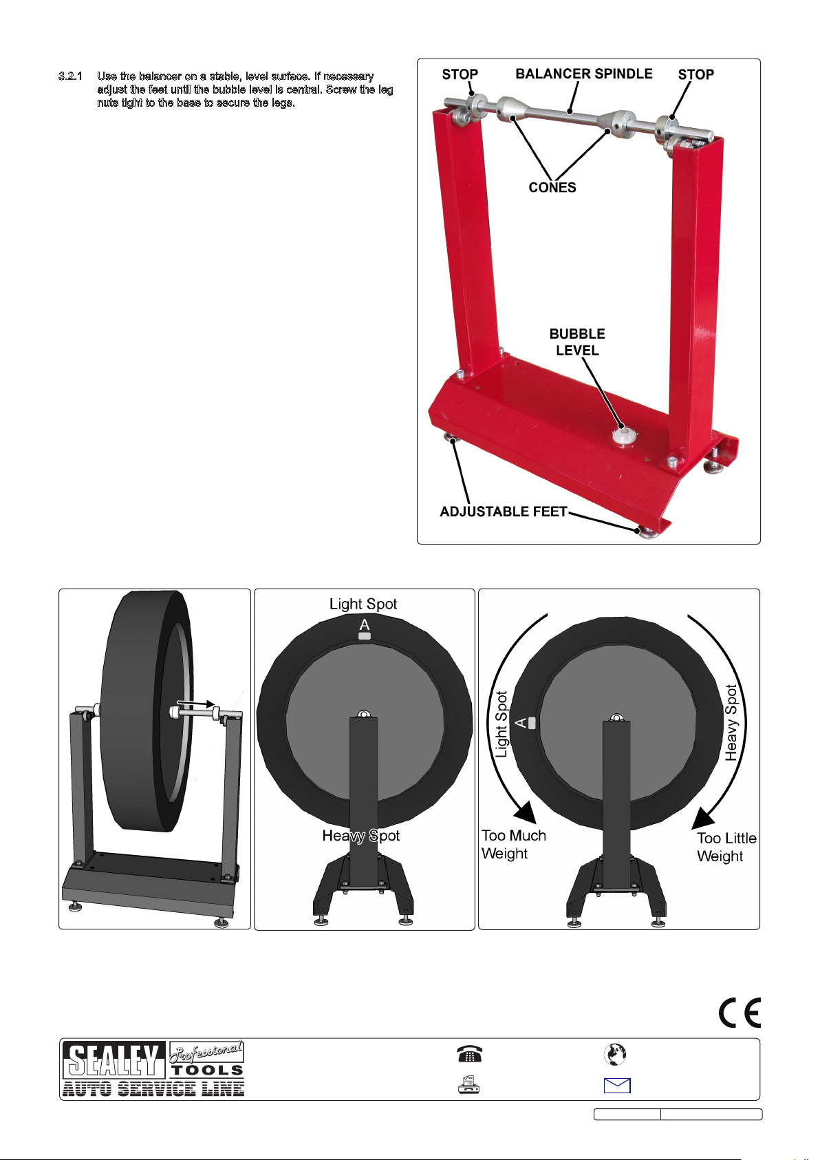
3.2.1 Use the balancer on a stable, level surface. If necessary
adjust the feet until the bubble level is central. Screw the leg
nuts tight to the base to secure the legs.
3.2.2 Slide the balancer spindle through the motorcycle wheel
hollow axle and slide a cone onto either end of the spindle so
that the tapered ends enter the wheel bearings. When the
wheel is central on the spindle, secure the cones by
tightening the grub screw in each using a 3mm hex key.
Check that the wheel is central on the spindle and firmly
secured by the cones for best results. At either end of the
spindle slide on the two circular stops, then place onto the
bearings on the two uprights. Move the stops to the outer
ends of the spindle but allow a small gap clearance to avoid
the bearing securing screws interfering with the spindle
movement. Tighten the grub screw within the stops to secure
them to the spindle. See fig.3
3.2.3 With the wheel securely on the wheel balancer, gently rotate
the wheel. When the wheel settles, the spot at the bottom of
the wheel is the "heavy spot."
3.2.4 Now with the heavy spot at the bottom mark the top of the
wheel directly opposite the heavy spot using chalk or
adhesive tape. This is the "light spot" see fig.4A.
3.2.5 Gently spin the wheel again to ensure that the heavy spot will
again settle at the bottom. (fig.4)
3.2.6 Attach some wheel weights to the rim of the wheel at the
"light spot" (fig.4A) and spin the wheel gently.
3.2.7 If the "light spot" falls to the bottom, too much weight has
been added to the wheel. If the heavy spot falls to the bottom,
not enough weight has been added to the wheel. Add /
Remove weight as required (fig.5)
3.2.8 Turn the "light spot" 90 degrees so it sits horizontally with the
heavy spot and observe its movements, if again it falls to the
bottom, too much weight has been added, if the "heavy spot"
falls, too little weight has been added. (fig.5)
3.2.9 Repeat until the light spot and heavy spot are on a horizontal
line through the centre of the wheel. Once this has been
achieved the wheel should rest still at any position through
the wheels circumference.
g.3 g.3 g.4 g.5
VS1819.V2 Issue: 1 - 14/07/11
Original Language Version
g.2
NOTE: It is our policy to continually improve products and as such we reserve the right to alter data, specifications and component parts without prior notice.
IMPORTANT: No liability is accepted for incorrect use of this product.
WARRANTY: Guarantee is 12 months from purchase date, proof of which will be required for any claim.
INFORMATION: For a copy of our latest catalogue and promotions call us on 01284 757525 and leave your full name and address, including postcode.
Sole UK Distributor, Sealey Group,
Kempson Way, Suffolk Business Park,
Bury St. Edmunds, Suffolk,
IP32 7AR
01284 757500
01284 703534
sales@sealey.co.uk
www.sealey.co.uk
Web
email
Table of contents
Other Sealey Wheel Balancer manuals