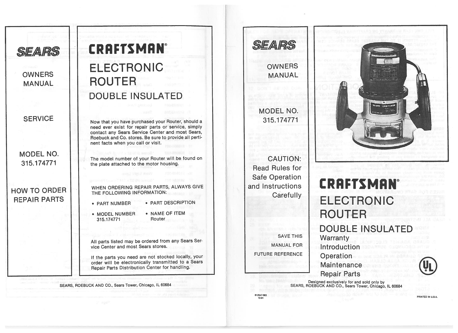
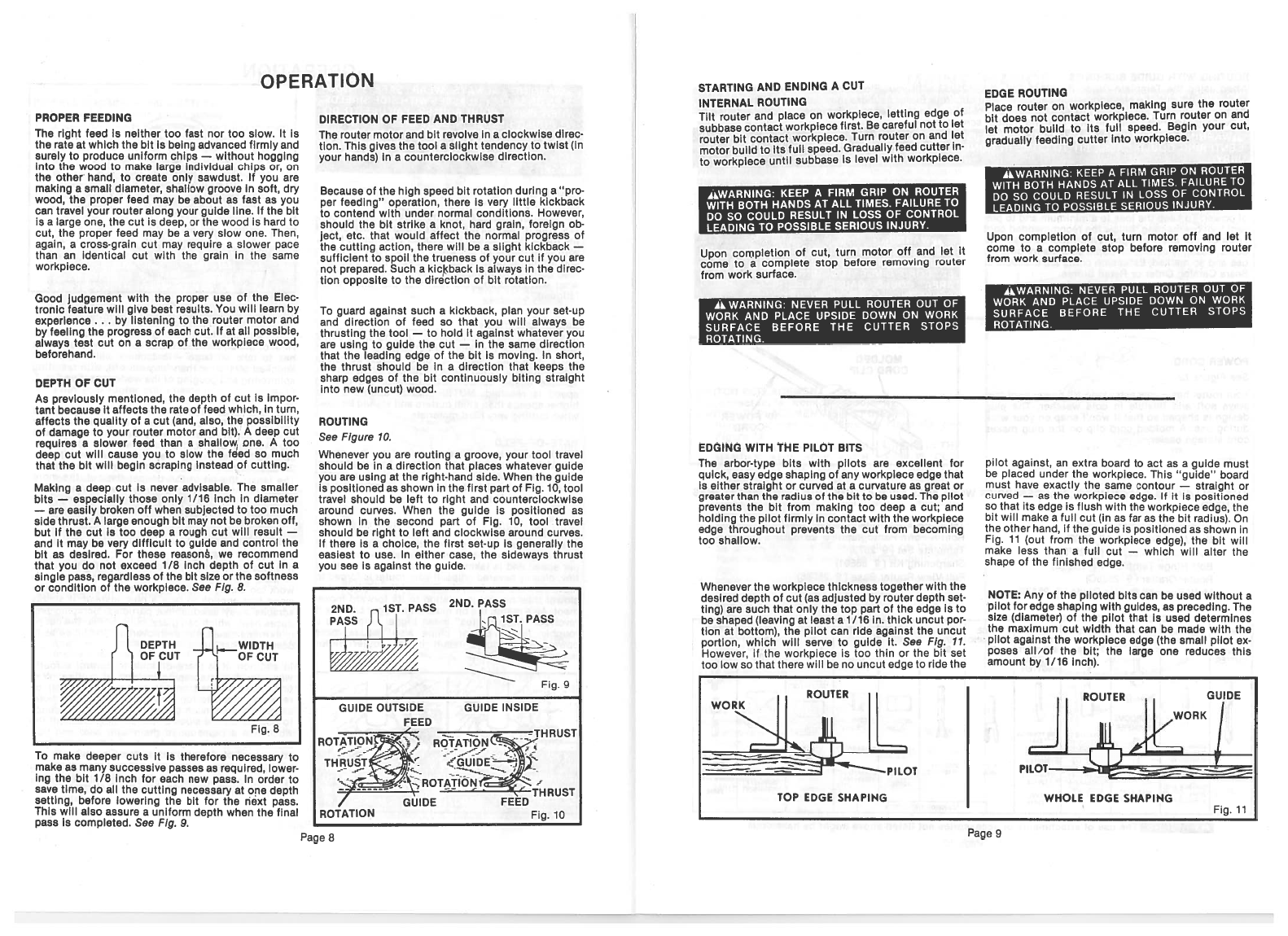
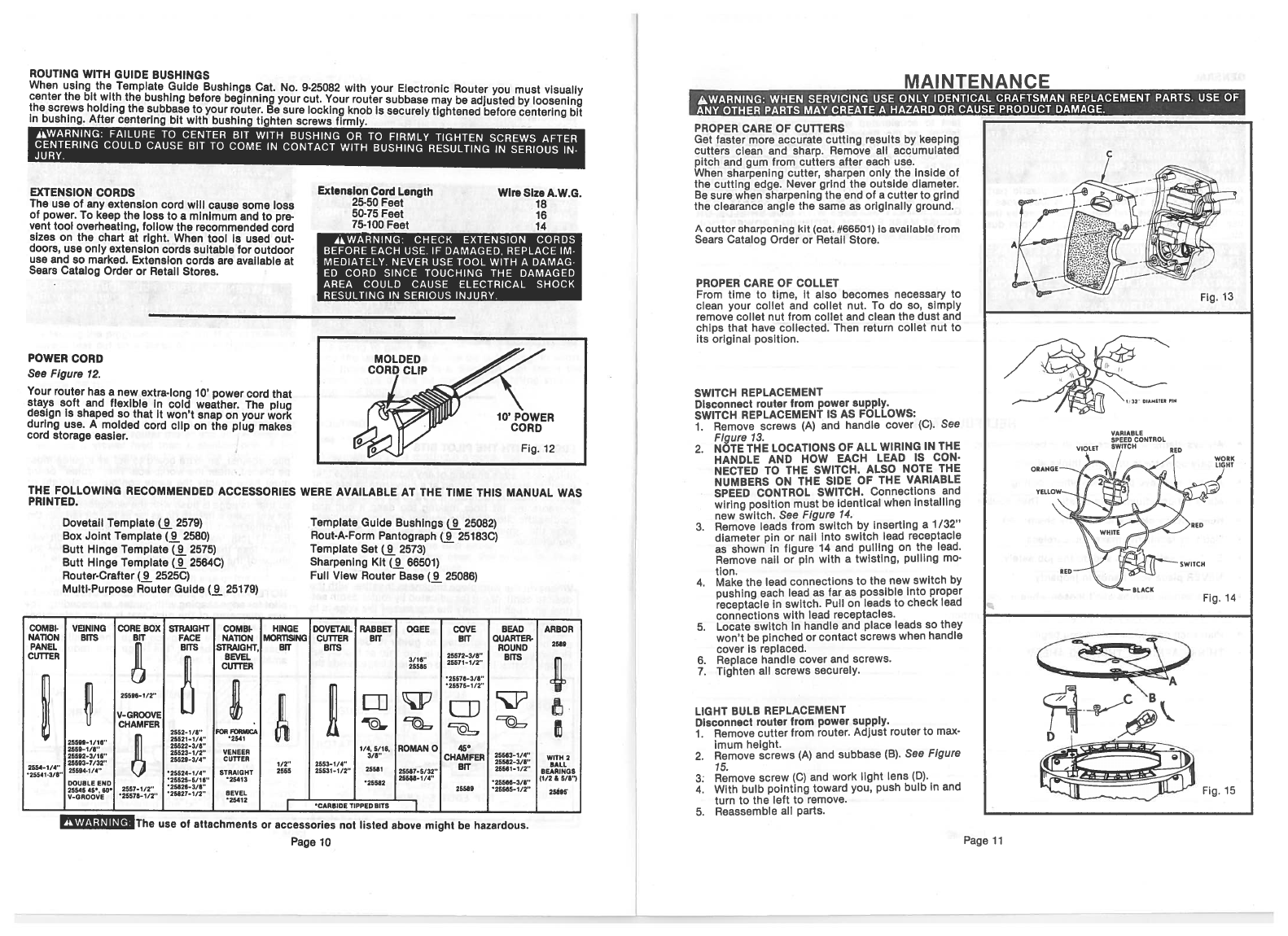
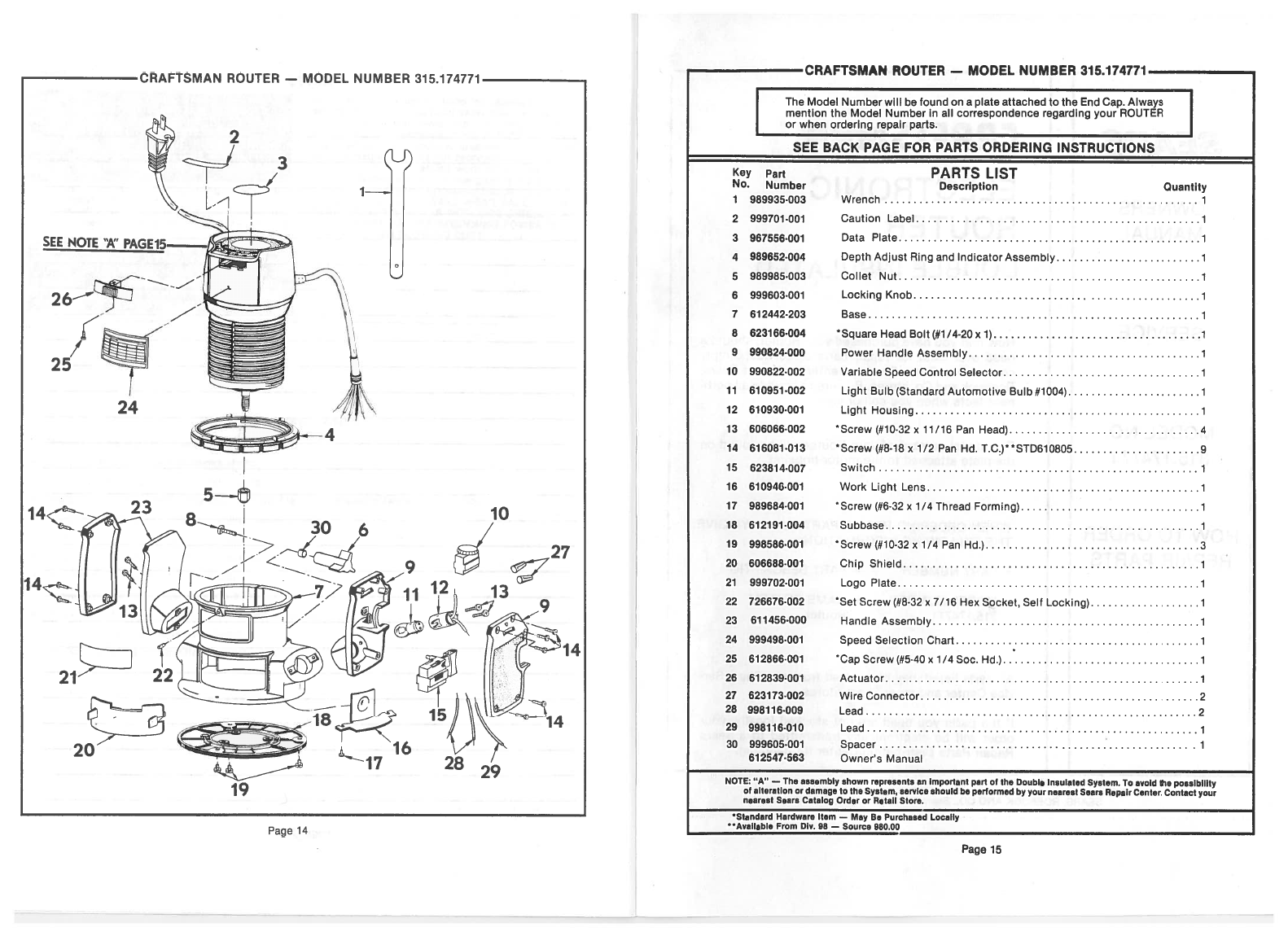
Sears CRAFTSMAN 315.174771 User manual

CRAFTSMAN®
ELECTRONIC
ROUTER
DOUBLE INSULATED
Now
that
you
have
purchased
your
Router,
should
a
need
ever
exist
for
repair
parts
or
service,
simply
contact
any
Sears
Service
Center
and
most Sears,
Roebuck
and
Co.
stores.
Be
sure
to
provide
all
perti
nent
facts
when
you
call or
visit.
The
model
number
of
your
Router
will
be found
on
the
plate
attached
to
the
motor
housing.
WHEN
ORDERING
REPAIR PARTS,
ALWAYS.
GIVE
THE
FOLLOWING INFORMATION:
•
PART
NUMBER
•
PART
DESCRIPTION
All
parts
listed
may
be
ordered
from
any
Sears
Ser
vice
Center
and
most
Sears
stores.
If
the
parts
you
need
are
not
stocked
locally,
your
order
will
be
electronically
transmitted
to
a
Sears
Repair
Parts
Distribution
Center
for
handling.
SAIR
OWNERS
MANUAL
SAVE
THIS
MANUAL
FOR
FUTURE
REFERENCE
Repair
Parts
SEARS,
ROEBUCK
AND
CO.,
Sears
Tower,
Chicago,
IL
60684
812047.563
10-91
Designed exclusively
for
and
sold
only
by
SEARS,
ROEBUCK
AND
CO.,
Sears
Tower,
Chicago,
IL
60684
SEAIR?S
OWNERS
MANUAL
SERVICE
MODEL
NO.
315.174771
HOW
TO
ORDER
REPAIR
PARTS
MODEL
NO.
315.174771
CAUTION:
Read
Rules
for
Safe Operation
and
Instructions
Carefully
•
MODEL
NUMBER
31
5.174771
•NAME
OF
ITEM
Router
CRAFTSMAN®
ELECTRONIC
ROUTER
DOUBLE INSULATED
Warranty
Introduction
Operation
Maintenance
PRINTED
IN
U.S.A.

READ
ALL
INSTRUCTIONS
INTRODUCTION
1.
KNOW
YOUR
POWER
TOOL
—
Read
owner’s manual carefully.
Learn
its
ap
plications
and
limitations as
well
as the
specific
potential
hazards
related
to
this
tool.
2.
GUARD
AGAINST
ELECTRICAL
SHOCK
BY
PREVENTING
BODY
CONTACT
WITH
GROUNDED
SURFACES. For
example: Pipes,
radiators,
ranges,
ref
rig
erator
enclosures.
3.
KEEP
GUARDS
IN
PLACE
and
in
working
order.
4.
KEEP
WORK
AREA CLEAN.
Cluttered
areas
and
benches
invite
accidents.
5.
AVOID
DANGEROUS
ENVIRONMENT. Don’t
use
power
tool
in
damp
or
wet
locations
or
expose
to
rain.
Keep
work
area
well
lit.
6.
KEEP
CHILDREN
AWAY.
All
visitors should
wear
safety
glasses
and
be
kept
a
safe
distance
from
work
area.
Do
not
let
visitors
contact
tool or
extension
cord.
7.
STORE
IDLE
TOOLS.
When not
in
use,
tools
should
be
stored
in
a
dry,
high
or
locked-up
place
—
out
of
the
reach
of
children.
RULES
FOR
SAFE
OPERATION
(Continued)
8.
DON’T
FORCE
TOOL.
It
will
do
the
job
better
and
safer
at
the
rate
for
which
it
was
designed.
9.
USE
RIGHT
TOOL.
Don’t
force
small
tool
or
attachment
to
do
the
job
of
a
heavy
duty
tool.
Don’t
use
tool
for
purpose
not
intended
—
for
example
—
Don’t
use
a
circular
saw
for
cutting
tree
limbs
or
logs.
70.
WEAR
PROPER
APPAREL.
No
loose
clothing
or jewelry
to
get
caught
in
moving
parts. Rubber gloves
and
non-skid
footwear
are
recommended
when
working
outdoors.
Also,
wear
protective
hair
covering
to
contain
long
hair and
keep
it
from
being
drawn
into air
vents.
11.
USE
SAFETY
GLASSES
with
all
tools.
Also
face
or
dust
mask
if
operation
is
dusty.
12.
DON’T
ABUSE CORD.
Never
carry
tool
by
cord
or
yank
it
to
disconnect
from
receptacle.
Keep
cord
from
heat,
oil,
and
sharp
edges.
13.
SECURE
WORK.
Use
clamps
or
a
vise
to hold
work.
It’s
safer
than
using
your
hand
and
it
frees
both
hands
to
operate
tool.
14.
DON’T
OVERREACH.
Keep
proper
footing
and
balance
at
all
times.
Do
not
use
on
a
ladder
or
unstable
support.
15.
MAINTAIN
TOOLS
WITH
CARE.
Keep
tools
sharp
at
all
times,
and
clean
for
best
and
safest
performance.
Follow
instructions
for
lubricating
and
changing
ac
cessories.
16.
DISCONNECT
TOOLS
FROM
POWER SUPPLY.
When
not
in
use,
before
serv
icing,
or
when
changing
attachments,
blades,
bits,
cutters,
etc.,
all
tools
should
be
disconnected
from
power
supply.
17.
REMOVE
ADJUSTING
KEYS AND
WRENCHES.
Form
habit
of
checking
to
see
that
keys
and
adjusting
wrenches
are
removed
from
tool
before
turning
it
on.
78.
AVOID
ACCIDENTAL
STARTING.
Don’t
carry
plugged-in
tools
with
finger
on
switch.
Be
sure
switch
is
off
when
plugging
in.
19.
OUTDOOR
USE
EXTENSION
CORDS.
When
tool
is
used
outdoors,
use
only
extension
cords
suitable
for
use outdoors.
Outdoor approved
cords
are marked
with
the
suffix
W-A,
for
example
—
SJTW-A
or
SJOW-A.
20.
KEEP
CUTTERS
CLEAN
AND
SHARP.
Sharp
cutters
minimize
stalling
and
kickback.
21.
KEEP
HANDS
AWAY
FROM CUTTING AREA.
Keep
hands
away
from
cutters.
Do
not
reach
underneath
work
while
cutter
is
rotating.
Do
not
attempt
to
re
I
move
material
while
cutter
is
rotating.
22.
NEVER USE
IN
AN
EXPLOSIVE
ATMOSPHERE. Normal
sparking
of
the
motor
could
ignite
fumes.
23.
INSPECT
TOOL
CORDS
PERIODICALLY
and
if
damaged,
have
repaired
at
your
nearest
Sears
Repair Center. Stay
constantly
aware
of
cord
location.
24.
INSPECT
EXTENSION
CORDS
PERIODICALLY
and
replace
if
damaged.
25.
KEEP
HANDLES
DRY,
CLEAN,
AND
FREE
FROM
OIL
AND
GREASE.
Always
use
a
clean
cloth
when
cleaning.
Never
use
brake fluids,
gasoline,
petroleum
based products,
or
any
strong
solvents
to
clean
your
tool.
26. STAY
ALERT.
Watch
what
you
are
doing
and
use
common
sense.
Do
not
op
erate
tool when
you
are tired.
Do
not
rush.
27.
CHECK
DAMAGED
PARTS.
Before
further
use
of
the
tool,
a
guard
or
other
part
that
is
damaged
should
be
carefully
checked
to
determine
that
it
will
operate
properly
and
perform its
intended
function.
Check
for
alignment
of
mov
ing
parts,
binding
of
moving
parts,
breakage
of
parts,
mounting,
and
any
other
conditions that
may
affect
its
operation.
A
guard
or
other
part
that
is
damaged
should
be
properly
repaired
or
replaced
by
an
authorized
service
center.
28.
DO
NOT
USE
TOOL
IF
SWITCH
DOES
NOT
TURN
IT
ON
AND
OFF.
Have
defect
ive
switches
replaced
by
authorized service
center.
29.
Inspect
for
and
remove
all
nails
from
lumber
before
routing.
30.
DRUGS,
ALCOHOL,
MEDICATION.
Do
not
operate
tool
while
under the
influ
ence
of
drugs, alcohol,
or
any
medication.
FULL
ONE
YEAR
WARRANTY
ON
CRAFTSMAN ELECTRONIC
ROUTER
If
this
Craftsman Electronic
Router
fails
to
give
complete
satisfaction
within
one
year
from
the
date
of
purchase
RETURN
IT
TO
THE
NEAREST
SEARS
SERVICE
CENTER/DEPARTMENT
THROUGHOUT
THE
UNITED
STATES
and
Sears
will
repair
It,
free
of
charge.
If
this
router
is
used
for
commercial
or
rental
purposes
this
warranty
applies
for only
90
days
from
the
date
of
purchase.
This
warranty
gives
you
specific
legal
rights, and
you may
also
have
other
rights
which
vary
from
state
to
state.
SEARS,
ROEBUCK
AND
CO.
DEPT.
731CR-W
SEARS
TOWER
CHICAGO,
IL
60684
DOUBLE
INSULATION
is
a
concept
In
safety,
In
elec
tric
power
tools,
which
eliminates
the
need
for
the
usual
three
wire
grounded
power
cord and
grounded
supply
system.
Wherever
there
is
electric
current
In
the
tool
there
are
two
complete
sets
of
insulation
to
protect
the
user.
All
exposed
metal
parts
are Isolated
from
the
Internal
metal
motor
components
with
pro
tecting
insulation.
IMPORTANT
—
Servicing
of
a
tool
with
double
in
sulation requires
extreme
care
and
knowledge
of
the
system
and
should
be
performed
only
by
a
qualified
service
technician.
For
service
we
suggest
you
return
the
tool to
your
nearest
Sears
Store
for
repair.
Always
use
original
factory
replacement
parts
when
servicing.
GENERAL
Your
electronic
router
is
a
versatile
woodworking
tool which
will
give you
years
of
trouble-free
perfor
mance.
It
is
engineered
with
the professional
in
mind,
but its
ease
of
operation
allows
the
amateur
to
produce
work
which
is
beautiful
and
precise.
Your
new
router has advanced
electronic
features
which
are
designed
to
assist
you
In
getting
the
maximum
use
from
your
router.
By
making
the
proper
speed
selections,
your
router
can
be
adjusted
to
your
specific
routing
needs.
This
eliminates
much
of
the
guess
work
previously
needed
to
perform a
given
job.
Both
the
experienced
and
inexperienced
router
users
benefit,
obtaining
professional
like
results
with
fewer
job
errors.
RULES
FOR
SAFE
OPERATION
The
electronic
feature
of
your
router
introduces the
flexibility
of
adjusting
the motor
speed
to
the
re
quired job
conditions.
The
speed
can
be
set
accor
ding to
the
approximate
cutter
diameter
you
will
be
using
and to
the
hardness
of
the
material
being cut.
Also,
the
best
cuts
are
made
when
the
cutter
is
fed
through
the
materIal
at
the
proper
rate. When
possi
ble,
you
should
make
practice
cuts
on
a
scrap piece
of
wood
to
get
a
‘feel”
of
how
fast
to
“feed”
your
router.
A
WARNING
—
DO
NOT
ATTEMPT
TO
OPERATE
THIS
TOOL
UNTIL
YOU
HAVE
READ
THOROUGHLY
AND
UNDERSTAND COMPLETELY
ALL
INSTRUCTIONS,
SAFETY RULES,
ETC.
CONTAINED
IN
THIS
MANUAL.
FAILURE
TO
COMPLY
CAN
RESULT
IN
ACCIDENTS
INVOLVING
FIRE, ELECTRIC
SHOCK,
OR
SERIOUS
PERSONAL
INJURY.
SAVE
OWNERS
MANUAL AND REVIEW
FREQUENTLY FOR
CONTINUING
SAFE OPERATION,
AND
INSTRUCTING
POSSIBLE
THIRD-PARTY
USER.
Page
2
Page
3

RULES
FOR
SAFE
OPERATION
(Continued)
31.
DO
NOT USE
TOOL UNDER
“BROWN-OUT”
OR
OTHER
LOW
VOLTAGE
CON.
DITIONS.
Also,
do
not
use
with
any
device
that
could
cause
the
power
supply voltage
to
change.
32. WEAR
HEARING
PROTECTION
DURING
EXTENDED
PERIODS OF
OPERATION.
33.
SAVE
THESE INSTRUCTIONS.
Refer
to
them
frequently
and
use
them
to
instruct
third
users.
If
you loan
someone
this
tool,
loan
them
these
instructions
also.
ANiNJ
The
operation
of
any
Router
can result
in
foreign
objects
being
thrown
Into
your
eyes,
which
can
result
In
severe
eye
damage.
Before
commencing
power
tool
operation,
always wear
safety goggles
or
safety
glasses
with
side
shields
and
a
full
face shield
when
needed.
We
recommend
Wide
Vision
Safety
Mask
for
use
over
spectacles
or
standard
safety
glasses
with
side
shields,
available
at
Sears
Catalog
Order or
Retail
Stores.
OPERATION
VARIABLE
SPEED
Your
electronic
router has
a
variable
speed
control
selector
designed
to
allow
operator
control
of
speed
and
torque
limits.
See
FIgure
7.
To
Increase
the
speed
and
torque
of
your
electronic
router, turn
the
variable
speed
control
selector
to
a
higher
setting.
Turn
to
a lower
setting
to
decrease
the
speed
and
torque
of
your
electronic
router.
NOTE:
If
you
desire
not
to
use the
variable
speed
control
selector,
turn to
the
highest
possible
setting
and
the electronic
feature
will
be
by.passed.
OPERATION
KNOW
YOUR
ELECTRONIC
ROUTER
Before
attempting
to
use
your
router,
familiarize
yourself
with
all
operating
features, electronic
features,
and
safety
requirements.
See
Figure
1.
AWARNING:
DO
NOT ALLOW
FAMILIARITY
WITH
YOUR
ROUTER
TO
MAKE
YOU
CARELESS.
REMEMBER
THAT
A
CARELESS
FRACTION
OF
A
SECOND
IS
SUFFICIENT
TO
INFLICT
SEVERE
INJURY.
We
suggest
that
you
practice
with
the electronic
features
of
your
router before
installing
a
cutter
and
making
cuts
in
wood.
CHECK THE
FOLLOWING
BEFOAE
CONNECTING
YOUR
ROUTER
TO
POWER
SUPPLY:
1.
Make
sure
power supply
Is
110.120
volts,
60
Hz,
AC
only.
2.
Make
sure
the
spindle
lock
is
in
the
unlocked
position.
3.
Make
sure the
trigger
is
not
in
the
‘lock-on”
posi
tion.
4.
Make
sure there
Is
not a
cutter
in
the
collet.
5.
Make
sure the
coilet
does
not
extend
below
the
subbase.
6.
Choose
the desired
speed
from
the
speed
selec
tion
chart.
See
Figure
2.
7.
Turn
the
variable
speed
control
selector
to
the
desired setting.
See
Figure
2.
Next
plug
your
router
into
power
supply
source.
Grasp
your
router
firmly
with
both
hands
and
turn
on.
SAHYASSfS
AWARNING:
YOUR
ROUTER
SHOULD
NEVER
BE
PLUGGED
IN
WHEN
YOU
ARE
ASSEMBLING
PARTS
OR
MAKING
ADJUSTMENTS.
FAILURE
TO
DO
SO
COULD
RESULT
IN
ACCIDENTAL STAR.
tING
OF
YOUR
ROUTER
RESULTING
IN
POSSIBLE
SERIOUS
INJURY.
ALWAYS
WEAR SAFETY
GOG.
GLES
OR
SAFETY
GLASSES
WITH
SIDE
SHIELDS
BEFORE
BEGINNING
POWER
TOOL
OPERATION.
If
any
parts
are
missing
do
not
operate
your
Router
until
the
missing
parts
are
replaced.
See
Figure
7.
CHIP SHIELD
A
clear plastic
chip
shield
is
installed
on
the
front
of
your
router
for
protection
against
flying
dust
and
chips.
The
chip
shield
is
designed
to
fit
the
front
opening
of
the
router
base
as
shown
in
figure
1.
If
SWITCH
The
switch
of
your
electronic
router
is
equipped
with
a
“lock-on”
feature
which
is
convenient
when
operating
for
extended
periods
of
time.
To
lock
on,
depress
the
trigger,
push
In
the
lock
button located
on
the side
of
the
handle,
then
while
holding
the
lock
button
pushed
in,
release
the
trigger.
To
release
the
lock,
depress
the
trigger
and
release
it.
necessary
to
remove,
squeeze
the
tabs
on
each
end
and
pull
outward.
To
replace,
squeeze
the
tabs
at
each
end,
fit
Into
the
opening,
then release.
FOR
YOUR
PROTECTION
DO
NOT
USE
ROUTER
WITHOUT
CHIP
SHIELD
PROPERLY
IN
PLACE.
AWARNING:
BEFORE
CONNECTING
YOUR
ROUTER
TO
POWER SUPPLY
SOURCE,
ALWAYS
CHECK
TO
BE
SURE
IT
IS
NOT
IN
“LOCK-ON”
POSITION.
FAILURE TO
DO
SO
COULD
RESULT
IN
ACCIDENTAL
STARTING
OF
YOUR
ROUTER
RESULTING
IN
POSSIBLE
SERIOUS
INJURY.
REAR
VIEW
Fig.
1
SPEED
SELECTION
VARIABLE
SPEED
CONTROL SELECTOR
DEPTH
ADJUSTING
RING
INDICATOR
POINT
CHIP SHIELD
FRONT
VIEW
Fig.
1
SELECTOR
Fig
2
Page
4
Page
5

OPERATION
INSTALLING/REMOVING
CUTTERS
Disconnect
router
from
power supply.
1. A
spindle
lock
Is
located
on
the
front
of
motor
housing.
See
Figure
5.
To
activate
lock,
push
spindle
lock
in
and
slide
into lock
position.
NEVER
ATTEMPT
TO
ACTIVATE
SPINDLE
LOCK
WHILE
ROUTER
MOTOR
IS
RUNNING
OR
COASTING
TO
A
STOP.
2.
Place
your
router
upside
down
on
a
table, then
turn
collet
nut
with
wrench
until
lock
mechanism
interlocks.
See
Fig.
3.
NOTE:
Spindle
lock
is
spring
loaded
and
will
snap
into
position
when
lock
mechanism
interlocks.
AWARNING:
IF YOU
ARE
CHANGING
A
CUTTER
IMMEDIATELY
AFTER USE,
BE
CAREFUL
NOT TO
TOUCH
THE
CUTTER
OR
COLLET
WITH
YOUR
HANDS
OR
FiNGERS.
THEY
WILL
GET BURNED
BECAUSE OF
THE
HEAT
BUILDUP
FROM CUTTING.
ALWAYS
USE
THE
WRENCH
PROVIDED.
3.
Remove
cutters
by
turning
collet
nut
counter
clockwise
enough
to
allow
cutter
to
slip easily
from
collet.
See
Figure
4.
The
collet
is
machined
to
precision
tolerances
to
fit
cutters
with
1/4”
diameter shank
size.
4.
With
your
router
still
upside
down
on
table,
in
sert
shank
of
cutter
into
collet.
The
shank
of
your
cutter
should
be
close
to
but
not
touching
bot
tom
of
collet.
5.
Tighten
the
collet
nut
securely
by
turning
clockwise
with
the
wrench
provided.
See
Fig.
4.
Put
spindle
lock
back
in
unlock
position.
Other
wise
the
interlocking
mechanism
of
the spindle
lock
will
not
let
your
router
turn
on.
DEPTH
OF
CUT
ADJUSTMENTS
We
recommend
that
cuts
be
made
at
a
depth
not
ex
ceeding
1/8”
and
that
several
passes
be
made
to
reach
depths
of
cut
greater
than
1/8”.
Disconnect
router
from
power
supply before
ad
justing
for
depth
of
cut.
1.
Place
the
router
on
a
flat
surface,
loosen
locking
knob,
and
turn
depth
adjusting
ring
until
cutter
Is
inside
subbase.
See
Figure
5.
2.
Turn
the
depth
adjusting
ring
until tip
of
cutter
touches
flat
surface.
Turn
the
depth
Indicator
ring
until
the
zero
lines
up
with
the
indicator
point
on
the
base. See
Figure
5.
3.
Position
the
router
so
that the
bit
can
extend
below
the
subbase
for
desired
depth
setting.
4.
Turn
the
depth
adjusting
ring
to obtain
the
desired
depth
of
cut.
The
distance
the
cutter
moves can
be
read
on
the
depth indicator
ring.
Each
notch
on
the depth adjusting
ring
indicates
1/64
inch
change
in
depth
setting.
5.
Tighten
locking
knob
securely
before operating
router.
ROUTING
See
Figure
6.
For
ease
of
operation
and
maintaining proper
con
trol,
your
router
has
two
handles,
one
on
each
side
of
the
router base.
Grasp
your
router
and
hold
it
firmly
with
both
hands as
shown
in
Fig.
6.
Turn
router
on
and
let
motor
build
to
its
full
speed,
then
gradually
feed
cutter
into
workpiece.
Remain
alert
and
watch
what
you
are
doing.
DO
NOT
operate
router
when
fatigued.
SPEED
SELECTION
In
general,
if
the
material being
cut
is
hard,
the
cutter
size
is
large, or
the
depth
of
cut
is
deep,
(maximum
1/8”),
then
your
electronic
router
should
be
run
at
slower
speeds.
When
these
situations
exist,
turn
the
variable
speed
control
selector
until
the desired
speed
is
reached.
NOTE:
Carbide
cutters
cut
at
higher
speeds
than
steel
cutters
and
should
be
used
when
cutting
very
hard
materials.
RATE-OF-FEED
IMPORTANT:
In
addition
to
selecting
the
proper
speed
for
your router,
the
“secret”
to
professional
routing and
edge
shaping
lies
in
making
a
careful
set-up
for
the cut
to
be
made and
in
selecting
the
proper
rate
of
feed.
FORCE
FEEDING
Clean,
smooth
routing and
edge
shaping
can
be
done
only
when
the
bit is
revolving
at
or
near
Its
pro
per
speed
and
is
taking
very
small
bites
to
produce
tiny,
cleanly
severed
chips.
If
your
router
is
forced
to
move
forward
too fast,
the
RPM
of
the
bit
becomes
slower than
normal
In
relation
to
its
forward
move
ment.
As
a
result,
the
bit
must take
bigger
bites
as
it
revolves.
“Bigger
bites”
mean
bigger
chips,
and
a
rougher
finish. Bigger
chips
also
require
more
power,
which
could
result
in
the
router
motor
becoming
overloaded.
Under
extreme
forcefeeding
conditions
the
relative
RPM
of
the
bit
can
become
so
slow
-
and
the bites
it
has
to
take
so
large
—
that
chips
will
be partially
knocked
off
(rather than
fully
cut
off),
with
resulting
splintering
and
gouging
of
the
workpiece.
See
Fig.
7.
Your
Craftsman
Electronic Router
is
a
high-speed
tool
(up
to
25,000
rpm
no-load
speed),
and
will
make
clean,
smooth
Cuts
if
allowed
to
run
freely
without
the
overload
of
a
forced
(too fast)
feed.
What
con
stitutes
“force-feeding”
depends
upon
three
things.
Bit
size,
depth-of-cut, and workpiece
characteristics.
The
larger
the
bit
or
the
deeper
the
cut,
the
more
slowly
the
router
can
be moved forward.
And,
if
the
wood
is
very
hard,
knotty,
gummy
or
damp,
the
operation must
be
slowed
still more.
TOO
SLOW FEEDING
It
Is
also
possible
to
spoil
a
cut
by
moving
the
router
forward
too
slowly.
When
it
is
advanced
into
the
work
too
slowly
a
revolving
bit
doesn’t
dig
into
new
wood
fast enough
to
take
a
bite;
instead,
it
simply
scrapes
away
sawdust-like
particles.
Scraping
pro
duces
heat,
which
can
glaze,
burn, or
mar
the
cut
—
in
extreme
cases,
can
even
overheat
the
bit
so
as
to
destroy
Its
hardness.
In
addition,
it
is
more
difficult
to
control
a
router
when
the
bit
is
scraping
Instead
of
cutting.
With
practically
no
load
on
the
motor,
the
bit
will
be
revolving
close
to
top
rpm
for
the
selected
speed,
and
will
have
a
much
greater
than
normal
tendency
to
bounce
off
the
sides
of
the cut (especially,
if
the
wood
has
a
pronounced
grain
with
hard
and
soft
areas).
As
a
result,
the
cut
produced
may
have
rippl
ed,
instead
of
straight,
sides.
See
Figure
7.
You
can
detect
“too-slow feeding”
by
the
no-load
sound
of
the
motor,
or
by
feeling
the
“wiggle”
of
the
bit
In
the
cut.
COLLET
NUT
OPERATION
AWARNING:
ALWAYS
WEAR
SAFETY
GOG
GLES
OR
SAFETY
GLASSES
WITH
SIDE
SHIELDS
WHEN
USING YOUR
ROUTER.
FAILURE
TO
DO
SO
COULD RESULT
IN
DUST
OR
CHIPS
BEING
THROWN
IN
YOUR EYES
RESULTING
IN
POSSI
BLE
SERIOUS
INJURY.
IF
THE
CUTTING
OPERA
TION
IS DUSTY,
ALSO
WEAR
A
FACE
OR
DUST
MASK.
Fig.
3
Fig.
6
TO
TIGHTEN
TO
LOOSEN
COLLET
NUT
COLLET
NUT
Fig
4
SPINDLE
LOCK1
LHNDICATOR
ADJUSTING
RING
Fig
5
AWARNING:
DO
NOT USE
CUTTERS
WITH
UNDERSIZED
SHANKS.
UNDERSIZED
SHANKS
WILL
NOT
TIGHTEN
PROPERLY
AND
COULD
BE
THROWN
FROM
TOOL CAUSING
INJURY.
WARNING:
BE
ABSOLUTELY CERTAIN
LOCK
1NG
KNOB
IS
FIRMLY
TIGHTENED.
FAILURE
TO
DO
THIS
WILL
RESULT
IN
THE
MOTOR
MOVING
INSIDE
THE
BASE,
CAUSING
AN
UNEVEN
CUT.
THIS
COULD
CAUSE
LOSS
OF CONTROL
RESULTING
IN
POSSIBLE
SERIOUS
INJURY.
Page
6
Page
7

PROPER
FEEDING
The
right
feed
Is
neither
too
fast
nor
too
slow.
It
is
the
rate
at which
the
bit
is
being
advanced
firmly
and
surely to
produce
uniform
chips
—
without hogging
Into
the
wood
to make
large
individual
chips
or,
on
the
other
hand,
to
create
only
sawdust.
If
you
are
making asmall
diameter,
shallow
groove
In
soft,
dry
wood,
the
proper
feed
may
be
about
as
fast as
you
can
travel
your
router
along
your
guide
line.
If
the
bit
is
a
large
one,
the
cut
is
deep,
or
the
wood
is
hard to
cut,
the
proper
feed
may
be
avery
slow one.
Then,
again,
a
cross-grain
cut
may
require
a
slower
pace
than
an
identical cut
with
the
grain
in
the
same
workpiece.
Good
judgement
with
the
proper
use
of
the
Elec
tronic
feature
will
give
best results.
You
will
learn
by
experience
-
-
.
by
listening
to
the
router
motor
and
by
feeling
the
progress
of
each
cut.
If
at
all
possible,
always
test
cut
on
a
scrap
of
the
workpiece
wood,
beforehand.
DEPTH
OF
CUT
As
previously
mentioned,
the
depth
of
cut
is
impor
tant
because
It
affects
the
rate
of
feed
which,
in
turn,
affects
the
quality
of a
cut
(and,
also,
the
possibility
of
damage
to
your
router
motor
and
bit).
A
deep
cut
requires
a
slower
feed
than
a
shallow
one.
A
too
deep
cut
will
cause
you
to
slow
the
feed
so
much
that
the
bit
will
begin
scraping
Instead
of
cutting.
Making
a
deep
cut
is
never
advisable.
The
smaller
bits
—
especially
those
only
1/16
Inch
in
diameter
—
are
easily
broken
off
when
subjected
to
too
much
side
thrust.
A
large
enough
bit
may
not be broken
off,
but
If
the
cut
Is
too
deep
a rough
cut
will
result
—
and
it
may be
very
difficult to
guide
and control
the
bit
as
desired.
For
these
reason,
we
recommend
that
you
do
not
exceed
1/8
inch
depth
of
cut
In
a
single
pass,
regardless
of
the
bit
size
or
the
softness
or
condition
of
the
workpiece.
See
Fig.
8.
To
make
deeper
cuts
it
is
therefore
necessary
to
make
as
many
successive
passes
as
required,
lower
ing
the
bit
1/8
inch for
each
new
pass.
In
order
to
save
time,
do
all
the cutting
necessary
at
one
depth
setting,
before
lowering
the
bit
for
the
next
pass.
This
will
also
assure
a
uniform
depth
when
the
final
pass
is
completed.
See
Fig.
9.
DIRECTION
OF
FEED
AND
THRUST
The
router
motor
and
bit
revolve
in
a
clockwise
direc
tion.
This
gives
the
tool
a
slight
tendency
to
twist
(in
your
hands)
in
a
counterclockwise
direction.
Because
of
the
high
speed
bit
rotation
during
a
“pro
per
feeding”
operation,
there
is
very
little
kickback
to
contend
with
under
normal
conditions.
However,
should
the
bit
strike
a
knot,
hard grain,
foreign
ob
ject,
etc.
that
would
affect
the
normal
progress
of
the
cutting action,
there
will
be
a
slight
kickback
—
sufficient
to
spoil
the
trueness
of
your
cut
if
you
are
not
prepared. Such
a
kickback
is
always
in
the
direc
tion
opposite
to
the
direction
of
bit
rotation.
To
guard
against such
a
kickback,
plan
your
set-up
and
direction
of
feed
so
that
you
will
always
be
thrusting the
tool
—
to
hold
it
against
whatever
you
are
using
to
guide
the
cut
—
in
the same
direction
that
the
leading
edge
of
the
bit
is
moving.
In
short,
the
thrust
should
be
in
a
direction
that
keeps
the
sharp
edges
of
the
bit
continuously
biting
straight
into
new
(uncut) wood.
ROUTING
See
Figure
10.
Whenever
you
are
routing
a
groove,
your
tool travel
should
be
in
a
direction that
places
whatever
guide
you
are
using
at
the
right-hand
side.
When
the
guide
is
positioned
as
shown
in
the
first part
of
Fig.
10,
tool
travel
should
be
left
to
right
and
counterclockwise
around
curves.
When
the
guide
Is
positioned
as
shown
in
the
second
part
of Fig.
10,
tool
travel
should
be
right to
left
and
clockwise
around
curves.
If
there
is
a
choice,
the
first
set-up
is
generally
the
easiest
to
use.
In
either
case,
the sideways thrust
you
see
Is
against
the
guide.
STARTING
AND
ENDING
A
CUT
INTERNAL ROUTING
Tilt
router
and
place
on
workpiece,
letting
edge
of
subbase
contact
workpiece
first.
Be
careful
not
to
let
router
bit
contact
workpiece.
Turn
router
on
and
let
motor
build
to
its
full
speed.
Gradually
feed
cutter
in
to
workplece
until
subbase
is
level
with
workpiece.
Upon
completion
of
cut,
turn
motor
off
and
let
it
come
to
a
complete
stop
before
removing
router
from
work
surface.
EDGING
WITH
THE
PILOT
BITS
The
arbor-type
bits
with
pilots
are
excellent
for
quick,
easy edge
shaping
of
any
workpiece
edge
that
is
either straight
or
curved
at
a
curvature
as
great
or
greater
than
the
radius
of
the
bit
to
be
used.
The
pilot
prevents
the
bit
from
making
too
deep
a
cut;
and
holding
the
pilot
firmly
in
contact
with
the
workpiece
edge
throughout prevents the cut
from
becoming
too
shallow.
Whenever
the
workplece
thickness
together
with
the
desired
depth
of
cut
(as
adjusted
by
router depth
set
ting)
are
such
that
only
the
top
part
of
the edge
is
to
be
shaped
(leaving at
least
a
1/16
in.
thick
uncut
por
tion at
bottom),
the
pilot
can
ride
against
the
uncut
portion, which
will
serve
to
guide
it.
See
Fig.
71.
However,
if
the
workpiece
is
too
thin
or
the
bit
set
too
low
so
that
there
will
be
no
uncut
edge
to
ride
the
EDGE
ROUTING
Place
router
on
workpiece,
making
sure the
router
bit
does
not
contact
workpiece.
Turn
router
on
and
let
motor
build to
its
full
speed.
Begin
your
cut,
gradually
feeding
cutter
into
workpiece.
Upon
completion
of
cut,
turn
motor
off
and
let
it
come
to
a
complete
stop
before
removing
router
from
work
surface.
pilot
against,
an
extra
board
to
act
as
a
guide must
be
placed under the
workpiece.
This
“guide”
board
must
have
exactly
the
same
contour
—
straight
or
curved
—
as the
workpiece
edge.
If
it
is
positioned
so
that
its
edge
is
flush
with
the workpiece edge, the
bit
will
make
a
full
cut
(in
as
far
as
the
bit
radius).
On
the
other
hand,
if
the
guide
is
positioned
as
shown
in
Fig.
11
(out
from
the
workpiece
edge),
the
bit
will
make
less
than
a
full
cut
—
which
will
alter
the
shape
of
the
finished edge.
NOTE:
Any
of
the piloted
bits
can
be
used
without
a
pilot
for
edge shaping
with
guides,
as
preceding.
The
size (diameter)
of
the
pilot
that
is
used
determines
the
maximum
cut
width
that
can
be
made
with
the
pilot
against
the
workplace
edge
(the
small pilot
ex
poses
all/of
the
bit;
the
large
one
reduces
this
amount
by
1/16
inch).
OPERATION
AWARNING:
KEEP
A
FIRM
GRIP
ON
ROUTER
WITH
BOTH
HANDS
AT
ALL
TIMES
FAILURE
TO
DO
SO
COULD
RESULT
IN
LOSS OF
CONTROL
LEADING
TO
POSSIBLE SERIOUS
INJURY.
AWARNING:
KEEP
A
FIRM
GRIP
ON
ROUTER
WITH
BOTH
HANDS
AT
ALL
TIMES.
FAILURE
TO
DO
SO
COULD RESULT
IN
LOSS
OF
CONTROL
LEADING
TO
POSSIBLE
SERIOUS
INJURY.
A
WARNING:
NEVER
PULL
ROUTER
OUT
OF
WORK
AND
PLACE UPSIDE
DOWN ON
WORK
SURFACE BEFORE
THE
CUTTER
STOPS
ROTATING.
AWARNING:
NEVER
PULL
ROUTER
OUT
OF
WORK
AND
PLACE UPSIDE
DOWN
ON
WORK
SURFACE
BEFORE
THE CUTTER
STOPS
ROTATING.
2ND.
1ST.
PASS
2ND.
PASS
PASS
1ST.
PASS
Fig.
9
GUIDE
OUTSIDE
GUIDE
INSIDE
FEED
-
-
-
—
-THRUST
ROTATIONS19
ROTATION
THRUST1
GUiDE—’7
—--iu’----
-:----w
--
-z
-
-
-
‘
THRUST
/
GUIDE
FEED
ROTATION
Fig.
10
ROUTER ROUTER
GUIDE
WORK
II
WORK
______________
PILOT
PILOT
—
—::::.-Z-
—--
TOP
EDGE
SHAPING
WHOLE
EDGE
SHAPING
Fig.
11
Page
9
Page
8

ROUTING
WITH
GUIDE
BUSHINGS
When
using
the
Template
Guide
Bushings
Cat.
No.
9-25082
with
your
Electronic Router
you
must
visually
center
the
bit
with
the
bushing
before beginning
your cut.
Your
router
subbase
may
be
adjusted
by
loosening
the
screws
holding
the
subbase
to
your
router.
Be
sure
locking knob
is
securely tightened
before
centering
bit
in
bushing.
After
centering
bit with
bushin
tiohten
screws
firmly.
EXTENSION
CORDS
The
use
of
any
extension
cord
will
cause
some loss
of
power.
To
keep
the loss
to
aminimum
and
to
pre
vent tool
overheating,
follow
the recommended
cord
sizes
on
the chart
at
right.
When tool
is
used
out
doors,
use
only
extension
cords
suitable
for
outdoor
use
and
so
marked.
Extension
cords
are
available
at
Sears
Catalog
Order
or Retail
Stores.
POWER
CORD
See
Figure
72.
Your
router
has
a
new
extra-long
10’
power cord
that
stays
soft
and flexible
in
cold
weather.
The
plug
design
is
shaped
so
that
it
won’t
snap
on
your
work
during
use.
A
molded
cord
clip
on
the
plug
makes
cord
storage
easier.
THE
FOLLOWING RECOMMENDED
ACCESSORIES
WERE
AVAILABLE
AT
THE
TIME
THIS
MANUAL
WAS
PRINTED.
COMBI- VEINING
CORE
BOX
STRAIGHT
COMBI-
HINGE
DOVETAIL
RABBET
OGEE
COVE
BEAD
ARBOR
NATION
BITS
BIT
FACE
NATION MORTISING
CUTTER
BIT BIT
QUARTER-
BITS
STRAIGHT,
BIT
BITS
ROUND
2589
PANEL
CUTTER
BEVEL
3/18”
BITS
CUTTER
25515
JD
25578—3/8”
25575—1/2”
25596—1/2”
V-GROOVE
CHAMFER
.
2552-1/8”
FOR
FOE58CA
25521—1/4”
2541
25598-1/18”
25522—3/8”
1/4, 5/16,
ROMAN
0
45
2559-1/8” 25523-1/2”
VENEER
3/8”
CHAMFER
25543-1/4”
WITH
2
25592-3/
16”
25529-3/4”
CUTtER
25562-3/8”
BALL
25593—7/32”
1/2”
2553—1/4”
BIT
25561—1/2”
2554—1/4”
25594-1/4”
25524-1/4”
STRAIGHT 2555
25531-1/2”
25541
25587-5/32”
BEARINGS
2554
1-3/8” 25525-5/1H”
25413 25512
25548-1/4”
25566-3/8”
1/2
&
5/81
DOUBLE
END
25545
45
95
2657-1/2”
25826-3/9”
25549 25565—1/2”
25895
V—GROOVE
25578-1/2”
25B27-1/2”
BEVEL
fl
ARBIDETIPPEDBITS
7
—
A
cutter
sharpening
kit
(cat.
#66501) is
available
from
Sears
Catalog
Order or
Retail
Store.
PROPER
CARE
OF
COLLET
From
time
to
time,
it
also
becomes necessary
to
clean
your
coliet
and
coilet
nut.
To
do
so,
simply
remove
collet
nut
from
coliet
and
clean
the
dust
and
chips
that
have
collected.
Then
return
collet
nut to
its
original
position.
SWITCH
REPLACEMENT
Disconnect router
from
power supply.
SWITCH
REPLACEMENT
IS
AS
FOLLOWS:
1.
Remove
screws
(A)
and
handle
cover
(C).
See
Figure
73.
2.
NOTE
THE
LOCATIONS
OF
ALL
WIRING
IN
THE
HANDLE
AND
HOW
EACH
LEAD
IS
CON
NECTED
TO
THE SWITCH.
ALSO NOTE
THE
NUMBERS
ON
THE
SIDE
OF
THE
VARIABLE
SPEED
CONTROL
SWITCH.
Connections
and
wiring
position
must
be
identical
when
installing
new
switch.
See
Figure
74.
3.
Remove
leads
from
switch
by
inserting
a
1/32”
diameter
pin
or
nail
into
switch
lead
receptacle
as
shown
in
figure
14
and pulling
on
the
lead.
Remove
nail
or
pin
with
a
twisting,
pulling
mo
tion.
4.
Make
the
lead
connections
to
the
new
switch
by
pushing
each
lead
as
far
as
possible
into
proper
receptacle
in
switch.
Pull
on
leads
to
check
lead
connections
with
lead
receptacles.
5.
Locate
switch
in
handle
and
place
leads
so they
won’t
be
pinched
or
contact screws
when
handle
cover
is
replaced.
6.
Replace handle
cover
and
screws.
7.
Tighten
all
screws
securely.
LIGHT
BULB
REPLACEMENT
Disconnect
router
from
power supply.
1.
Remove
cutter
from
router.
Adjust
router
to
max
imum
height.
2.
Remove
screws
(A)
and
subbase
(B).
See
Figure
75’
3;
Remove
screw
(C)
and
work
light
lens
(D).
4.
With
bulb
pointing toward
you,
push
bulb
in
and
turn
to
the
left
to
remove.
5.
Reassemble
all
parts.
AWARNING:
FAILURE
TO
CENTER
BIT
WITH
BUSHING
OR TO FIRMLY
TIGHTEN
SCREWS
AFTER
CENTERING
COULD
CAUSE
BIT
TO
COME
IN
CONTACT
WITH
BUSHING
RESULTING
IN
SERIOUS
IN
JURY.
Extension
Cord
Length
25-50
Feet
50-75
Feet
75.100
Feet
MAINTENANCE
AWARNING:
WHEN
SERVICING
USE
ONLY
IDENTICAL
CRAFTSMAN REPLACEMENT PARTS.
USE
OF
ANY
OTHER PARTS
MAY
CREATE
A
HAZARD OR
CAUSE
PRODUCT_DAMAGE.
__________________
Wire
Size
A.W.G.
18
16
14
PROPER
CARE
OF
CUTTERS
Get
faster
more
accurate
cutting
results
by
keeping
cutters
clean
and
sharp.
Remove
all
accumulated
pitch and
gum
from
cutters
after each
use.
When
sharpening
cutter,
sharpen
only
the
inside
of
the
cutting
edge.
Never
grind
the
outside
diameter.
Be
sure
when
sharpening
the
end
of a
cutter
to
grind
the
clearance
angle
the same as
originally
ground.
AWARNING:
CHECK EXTENSION
CORDS
BEFORE
EACH USE.
IF
DAMAGED,
REPLACE
IM
MEDIATELY.
NEVER USE
TOOL
WITH
A
DAMAG
ED
CORD
SINCE
TOUCHING THE
DAMAGED
AREA COULD
CAUSE
ELECTRICAL
SHOCK
RESULTING
IN
SERIOUS
INJURY.
Dovetail
Template
(..
2579)
Box
Joint
Template
(9
2580)
Butt
Hinge
Template
(9
2575)
Butt
Hinge
Template
(9
2564C)
Router-Crafter
(9
2525C)
Multi-Purpose
Router
Guide
(9
25179)
Template
Guide
Bushings
(9
25082)
Rout-A-Form
Pantograph
(
251
83C)
Template Set
(9
2573)
Sharpening
Kit
(9
66501)
Fuli
View
Router Base
(9
25086)
VT’1:1I[[eThe
use
of
attachments
or
accessories
not
listed
above
might
be
hazardous.
Page
10
Page
11

GENERAL
NOTES
4WARNING:
ONLY
THE PARTS
SHOWN
ON
PARTS
LIST,
PAGE
FIFTEEN,
ARE
INTENDED
TO
BE
REPAIRED
OR
REPLACED
BY
THE
CUSTOMER.
ALL
OTHER
PARTS
REPRESENT
AN
IMPORTANT
PART
OF
THE
DOUBLE
INSULA
TION
SYSTEM
AND
SHOULD
BE
SERVICED
ON.
LY
BY
A
QUALIFIED
SEARS
SERVICE TECHNI.
ClAN.
Avoid
using
solvents
when
cleaning
plastic
parts.
Most
plastics
are
susceptible
to various
types
of
commercial
solvents
and
may
be
damaged
by
their
use.
Use
clean
cloths
to
remove
dirt,
carbon
dust,
etc.
WARNING:
DO
NOT
AT
ANY
TIME
LET
BRAKE
FLUIDS,
GASOLINE, PETROLEUM.BASED PRO.
DUCTS,
PENETRATING
OILS,
ETC.
COME
IN
CONTACT
WITH
PLASTIC
PARTS.
THEY
CON
TAIN
CHEMICALS
THAT
CAN
DAMAGE,
WEAKEN,
OR
DESTROY
PLASTIC.
When
electric
tools
are
used
on.
fiberglass
boats,
sports
cars,
etc.,
It
has
been
found
that
they
are
sub
ject
to
accelerated
wear
and
possible
premature
failure,
as
the fiberglass
chips
and
grindings
are
highly
abrasive
to
bearings,
brushes,
commutators,
etc.
Consequently
It
Is
not
recommended that this
tool
be
used
for
extended
work
on
any
fiberglass
material.
During
any
use
on
fiberglass
It
is
extremely
Important
that
the
tool
is
cleaned
frequently
by
blow
ing
with
an
air
jet.
ALWAYS
WEAR
SAFETY
GOG.
GLES, SAFETY
GLASSES
WITH
SIDE
SHIELDS,
OR
A
DUST MASK
BEFORE
BEGINNING POWER
TOOL
OPERATION
OR
BLOWING
DUST.
HELPFUL
HINTS
•
Always
clamp workpiece
securely
before
routing.
•
A
safe operator
is
one
who
thiflks
ahead.
•
Always
wear
eye
protection
when
routing.
•
Make
set-up
adjustments
carefully.
Then
double check.
Measure
twice
and cut
once.
•
Keep
cutters
clean
and
properly
sharpened.
• Don’t
let
familiarity
make
you
careless.
•
Study
all
safety
rules
and do
the
job safely.
•
NEVER
place
your
hands
in
jeopardy.
•
Make
certain
clamps
can’t
loosen
while
in
use.
•
Test
difficult
set-ups
on
scrap
—
Don’t
waste
lumber.
•
Plan
each operation
before
you
begin.
•
THINK
SAFETY
BY
THINKING AHEAD.
-
.
-
4
Page
12
Page
13

_____________
____________
CRAFTSMAN
ROUTER
—
MODEL
NUMBER
315.174771
CRAFTSMAN
ROUTER
—
MODEL
NUMBER
315.174771
The
Model
Number
will
be found
on
a
plate
attached
to
the
End
Cap.
Always
mention
the
Model
Number
in
all
correspondence
regarding
your
ROUTER
or
when
ordering
repair
parts.
SEE
BACK
PAGE
FOR PARTS ORDERING
INSTRUCTIONS
Key
Part
PARTS
LIST
No.
Number
Description
Quantity
1
989935-003
Wrench
1
2
999701-001
Caution
Label
1
3
967556.001
Data
Plate
1
4
989652.004
Depth
Adjust
Ring
and
Indicator
Assembly
1
5
969985-003
Collet
Nut
1
6
999603-001
Locking
Knob
1
7
612442.203
Base
1
8
623166•004
*Square
Head
Bolt
(#1/4-20x1)
1
9
990824-000
Power Handle
Assembly
1
10
990822-002
Variable
Speed
Control
Selector
1
11
610951-002 Light Bulb
(Standard
Automotive
Bulb
#1004)
1
12
610930-001
Light
Housing
1
13
606066-002
*Screw
(#10.32
x
11/16
Pan
Head)
4
14
616081-013
*Screw
(#8-18
x
1/2
Pan
Hd.
T.C.)**STD610805
9
15
623814-007
Switch
1
16
610946-001
Work
Light
Lens
1
17
989684-001
Screw
(#6-32
x
1/4
Thread
Forming)
1
16
612191-004
Subbase
1
19
998586-001
*Screw
(#10-32
x
1/4
Pan
Ha.)
3
20
606688.001
Chip
Shield
1
21
999702-001
Logo
Plate
1
22
726676.002
Set
Screw
(#8-32
x
7/16
Hex
Socket,
Self
Locking)
1
23
611456-000
Handle
Assembly
1
24
999498-001
Speed Selection
Chart
1
25
612866-001
Cap
Screw
(#5-40x
1/4
Soc.
Ha.)
1
26
612839-001
Actuator
1
27
6231
73-002
Wire
Connector
2
28
998116-009 Lead
2
29
998116.010
Lead
1
30
999605-001
Spacer
1
612547.563
Owner’s
Manual
NOTE:
A”
—
The
assembly
shown
represents
an
Important part
of
the
Double
Insulated System.
To
avoId
the
possIbilIty
of
alteratIon
or
damage
to
the
System,
service
should
be
performed
by
your
nearest
Sure
RepaIr
Canter.
Contact
your
nearest
Sears
Catalog
Order
or
Retail
Store.
Standard
Hardware
Item
—
May
Be
Purchased
Locally
**Avaiiable
From
Dlv.
98
—
Source
980.00
—
_______________________________
2
3
SEE
24
14
19
Page
14
Page
15
Table of contents
Other Sears Wood Router manuals
Popular Wood Router manuals by other brands

Black & Decker
Black & Decker Elu 3303 instruction manual

Constructor
Constructor CR1050BC Original instructions

Makita
Makita RP1802 instruction manual

DeWalt
DeWalt DCW600B-CA instruction manual

F.F. Group
F.F. Group RO 1600 PLU Original instructions

EINHELL
EINHELL TE-RO 1255 E Original operating instructions

Mafell
Mafell LO 65 Ec Translation of the original operating instructions

Far Tools
Far Tools MR 40PB Original manual translation

Delta
Delta ShopMaster SH100 instruction manual

Virutex
Virutex FR277R operating instructions

Sealey
Sealey SV20 Series manual

CMT ORANGE TOOLS
CMT ORANGE TOOLS BTS-001 owner's manual