TYPE 670/675/676/680/ECS™
SEALOL®METAL BELLOWS EMISSION CONTAINMENT SEAL
Installation, Operation & Maintenance Instructions
3
3. Determine squareness of seal chamber face to shaft
(0.001 mm per mm/ 0.001" per inch of shaft diameter FIM max.),
and shaft concentricity to the seal chamber.
Typical Type MLS-1 Seal Arrangement
4
5
1
10
26 7 8 9 11 312
General Instructions
1. Study the engineering layout drawing to confirm that the seal gasket
and gland will mate successfully with the stuffing box. There are differ-
ent seal configurations depending on the design of the stuffing box.
Preparing the Equipment
1. Check the stuffing box dimensions and finishes.
2. Measure axial end play (±2.54mm/0.100" max.).
3. Measure shaft runout (±0.127mm/0.005" max.).
4. Measure squareness of the stuffing box to the shaft
(±0.051mm/0.002" max.).
NOTE: If measured dimensions
exceed those values
given, correct the
equipment to meet
specifications prior to
seal installation.
63
SHAFT OR SLEEVE
0.040 LG. X 20˚ CHAM.
BORE
0D +0.000"
-0.002"
63
MOVE SHAFT IN AXIAL DIRECTION
BY HAND. NOTE MEASUREMENT
ON DIAL INDICATOR
MOUNT
DIAL INDICATOR
ON SHAFT
TURN SHAFT BY HAND AND NOTE
MEASUREMENT ON DIAL INDICATOR
MOUNT
DIAL INDICATOR
ON SHAFT
TURN SHAFT BY HAND AND NOTE
MEASUREMENT ON DIAL INDICATOR
MOUNT
DIAL INDICATOR
ON SEAL CHAMBER
FACE
The MLS-1 seal is shipped fully assembled. When ordering a repair kit,
assemble the MLS-1 as follows, referring to the applicable engineering
layout drawing. This assembly is based on installing the repair kit into an
existing seal assembly.
NOTE: These instructions apply to the MLS-1, which is the standard MLS,
and should only be used when installing the components of the
repair kit. Other MLS seal types require different assembly
procedures. Contact John Crane Engineering.
Elastomeric o-rings can be damaged or destroyed if care is not
taken. Prior to assembly of o-rings into their respective grooves,
make sure groove is clean and free of foreign materials. Lubricate
both groove and o-ring prior to installation.
Removing Old Parts
1. Remove sleeve from gland. Save for assembly.
2. Place the gland on table with gasket side facing down.
3. Remove the retaining ring by applying a small flathead screwdriver
to the split in the ring.
4. Remove all interior components, saving the compression ring for
assembly. Remove O-ring from sleeve.
Do not reuse O-rings.
Assembling Repair Kit
1. With gasket side facing down, install a gland O-ring into the gland.
2. Insert the first sealing element into the gland with the end of the arc
facing down.
3. Install a gland O-ring onto the o-ring spacer in the OD groove.
Insert the O-ring spacer into the gland with O-ring side facing up.
4. Insert the second sealing element into the gland with the end of
the arc facing down. Insert the spacer into the gland with small
ID facing down.
5. Insert the third sealing element into the gland with the end of the arc
facing down. Install a gland O-ring onto the compression ring in the
OD groove.
6. Insert the compression ring into the gland with O-ring side
facing down.
(continued on page 3)
Type MLS-1 Seal Assembly (Repair Kit)
Part Name
1 Gland 7 Chemlon Seal
2 Sleeve 8 O-ring Spacer
3 Set Screws 9 Flush Spacer
4 Gasket 10 Retaining Ring
5 Gland O-ring 11 Setting Spacer
6 Sleeve O-ring 12 Compression Ring
!
TYPE MLS-1
CHEMLON CARTRIDGE SEAL
Installation, Operation & Maintenance Instructions
PAGE 2
4. Measure shaft runout (0.001mm/0.001" per inch per mm of shaft
diameter FIM max.).
Typical Type MLS-1 Seal Arrangement
4
5
1
10
26 7 8 9 11 312
General Instructions
1. Study the engineering layout drawing to confirm that the seal gasket
and gland will mate successfully with the stuffing box. There are differ-
ent seal configurations depending on the design of the stuffing box.
Preparing the Equipment
1. Check the stuffing box dimensions and finishes.
2. Measure axial end play (±2.54mm/0.100" max.).
3. Measure shaft runout (±0.127mm/0.005" max.).
4. Measure squareness of the stuffing box to the shaft
(±0.051mm/0.002" max.).
NOTE: If measured dimensions
exceed those values
given, correct the
equipment to meet
specifications prior to
seal installation.
63
SHAFT OR SLEEVE
0.040 LG. X 20˚ CHAM.
BORE
0D +0.000"
-0.002"
63
MOVE SHAFT IN AXIAL DIRECTION
BY HAND. NOTE MEASUREMENT
ON DIAL INDICATOR
MOUNT
DIAL INDICATOR
ON SHAFT
TURN SHAFT BY HAND AND NOTE
MEASUREMENT ON DIAL INDICATOR
MOUNT
DIAL INDICATOR
ON SHAFT
TURN SHAFT BY HAND AND NOTE
MEASUREMENT ON DIAL INDICATOR
MOUNT
DIAL INDICATOR
ON SEAL CHAMBER
FACE
The MLS-1 seal is shipped fully assembled. When ordering a repair kit,
assemble the MLS-1 as follows, referring to the applicable engineering
layout drawing. This assembly is based on installing the repair kit into an
existing seal assembly.
NOTE: These instructions apply to the MLS-1, which is the standard MLS,
and should only be used when installing the components of the
repair kit. Other MLS seal types require different assembly
procedures. Contact John Crane Engineering.
Elastomeric o-rings can be damaged or destroyed if care is not
taken. Prior to assembly of o-rings into their respective grooves,
make sure groove is clean and free of foreign materials. Lubricate
both groove and o-ring prior to installation.
Removing Old Parts
1. Remove sleeve from gland. Save for assembly.
2. Place the gland on table with gasket side facing down.
3. Remove the retaining ring by applying a small flathead screwdriver
to the split in the ring.
4. Remove all interior components, saving the compression ring for
assembly. Remove O-ring from sleeve.
Do not reuse O-rings.
Assembling Repair Kit
1. With gasket side facing down, install a gland O-ring into the gland.
2. Insert the first sealing element into the gland with the end of the arc
facing down.
3. Install a gland O-ring onto the o-ring spacer in the OD groove.
Insert the O-ring spacer into the gland with O-ring side facing up.
4. Insert the second sealing element into the gland with the end of
the arc facing down. Insert the spacer into the gland with small
ID facing down.
5. Insert the third sealing element into the gland with the end of the arc
facing down. Install a gland O-ring onto the compression ring in the
OD groove.
6. Insert the compression ring into the gland with O-ring side
facing down.
(continued on page 3)
Type MLS-1 Seal Assembly (Repair Kit)
Part Name
1 Gland 7 Chemlon Seal
2 Sleeve 8 O-ring Spacer
3 Set Screws 9 Flush Spacer
4 Gasket 10 Retaining Ring
5 Gland O-ring 11 Setting Spacer
6 Sleeve O-ring 12 Compression Ring
!
TYPE MLS-1
CHEMLON CARTRIDGE SEAL
Installation, Operation & Maintenance Instructions
PAGE 2
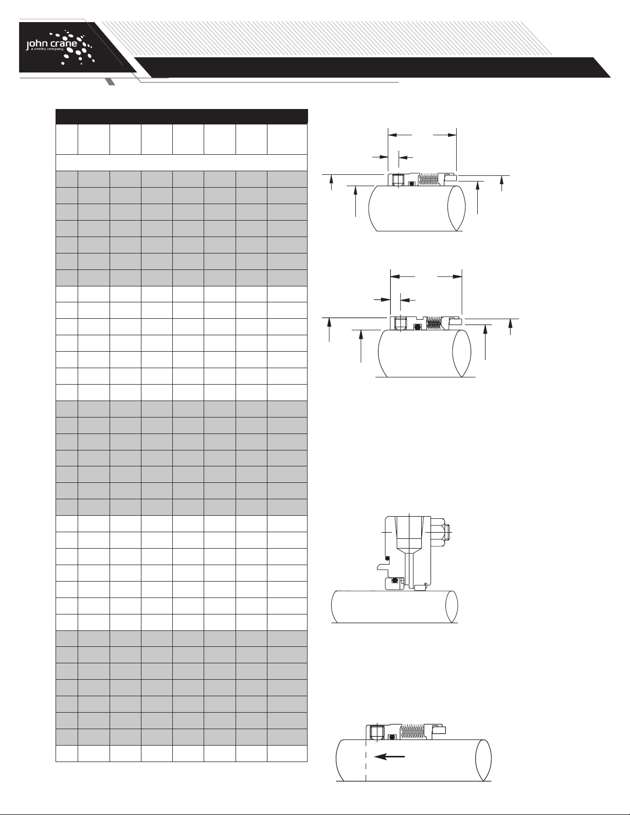
Component Seals
Setting the seal
1. With the seal chamber and shaft/sleeve in their correct operating
positions, use a straight edge to scribe the position of the seal
chamber face onto the shaft/sleeve at A. Use machinist’s blue to make
the scribe easier to see.
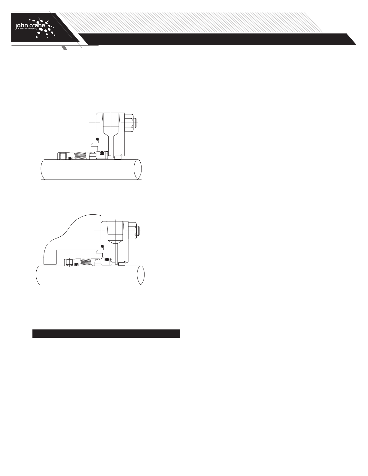
2. Again remove the pump housing. From the installation drawing,
determine the distance from the seal chamber face to the seal set
length, and scribe line B onto the shaft sleeve at this distance.
3. Without disturbing the scribe line B, wipe the shaft/sleeve clean and
apply a lubricant which is compatible with the sealed fluid and the
gasketing materials.
Type 670/675/676/680 Dimensional Data (mm)
Sealol
Dash
No.
Shaft
Size
A B C D E F
Set Screw
Size/Qty
670/680 670 680
-024 24.00 38.10 29.79 34.93 4.50 30.00 M5 x 3 M5 x 3
-025 25.00 39.00 30.50 35.68 4.50 30.00 M5 x 3 M5 x 3
-028 28.00 42.00 33.50 38.68 5.50 32.50 M5 x 3 M5 x 3
-030 30.00 44.00 35.50 40.68 5.10 32.50 M5 x 3 M5 x 3
-032 32.00 46.02 38.51 43.66 5.10 32.50 M5 x 3 M5 x 3
-033 33.00 47.00 38.20 44.63 4.50 32.50 M5 x 3 M5 x 3
-035 35.00 49.20 41.68 46.86 4.50 32.50 M5 x 3 M5 x 3
-038 38.00 52.37 43.59 50.04 5.20 34.00 M6 x 3 M6 x 3
-040 40.00 55.55 46.76 53.21 5.20 34.00 M6 x 3 M6 x 3
-043 43.00 58.72 49.94 56.39 5.20 34.00 M6 x 3 M6 x 3
-045 45.00 58.72 49.94 56.39 5.20 34.00 M6 x 3 M6 x 3
-048 48.00 61.90 53.09 59.56 5.00 34.00 M6 x 3 M6 x 3
-050 50.00 65.07 56.29 62.76 5.20 34.50 M6 x 3 M6 x 3
-053 53.00 68.25 59.44 65.91 5.20 34.50 M6 x 3 M6 x 3
-055 55.00 71.00 62.00 68.45 4.60 34.50 M6 x 3 M6 x 3
-058 58.00 74.60 65.79 72.29 6.60 39.50 M6 x 3 M8 x 3
-060 60.00 74.60 65.79 72.29 6.60 39.50 M6 x 3 M8 x 3
-063 63.00 80.95 70.87 78.64 6.60 39.50 M6 x 3 M8 x 3
-065 65.00 84.12 74.04 81.81 6.00 39.50 M6 x 3 M8 x 3
-068* 68.00 87.30 77.22 85.01 5.10 37.50 — M8 x 3
-070 70.00 87.30 77.22 85.01 8.20 45.00 M6 x 3 M8 x 3
-075 75.00 95.25 84.38 92.13 7.80 45.00 M6 x 3 M8 x 3
-080 80.00 98.43 87.30 95.81 6.70 44.50 M8 x 4 M8 x 3
-085 85.00 104.78 93.65 102.16 6.70 44.50 M8 x 4 M8 x 3
-090 90.00 107.95 96.82 105.33 9.00 49.50 M8 x 4 M8 x 3
-095 95.00 114.30 103.17 111.68 9.00 49.50 M8 x 4 M8 x 3
-100 100.00 120.65 109.52 118.03 9.00 49.50 M8 x 4 M8 x 3
-102 102.00 120.65 109.52 118.03 9.00 49.50 M8 x 4 —
-105 105.00 131.75 115.49 124.76 7.10 48.50 M8 x 4 —
-110 110.00 138.13 126.44 131.14 7.10 48.50 M8 x 4 —
-115 115.00 144.48 128.22 137.49 7.10 48.50 M8 x 4 —
-120 120.00 144.48 128.22 137.49 7.10 48.50 M8 x 4 —
-125 125.00 150.83 134.59 143.87 7.10 48.50 M8 x 4 —
-130 130.00 157.81 140.56 150.85 7.10 48.50 M8 x 4 —
-140 140.00 170.54 153.31 163.60 7.10 48.50 M8 x 4 —
-150 150.00 176.89 159.66 169.98 7.10 48.50 M8 x 4 —
NOTE: If measured
dimensions exceed those
values given, correct
the equipment to meet
specifications prior to
seal installation.
* 670 is not available in 68mm size.