Securefast SBL700 User manual

T/052A/SBL700
3rd January 2016
SBL700
Installation Instructions for SBL700 Push Button Lock with Knob Handle
Installation
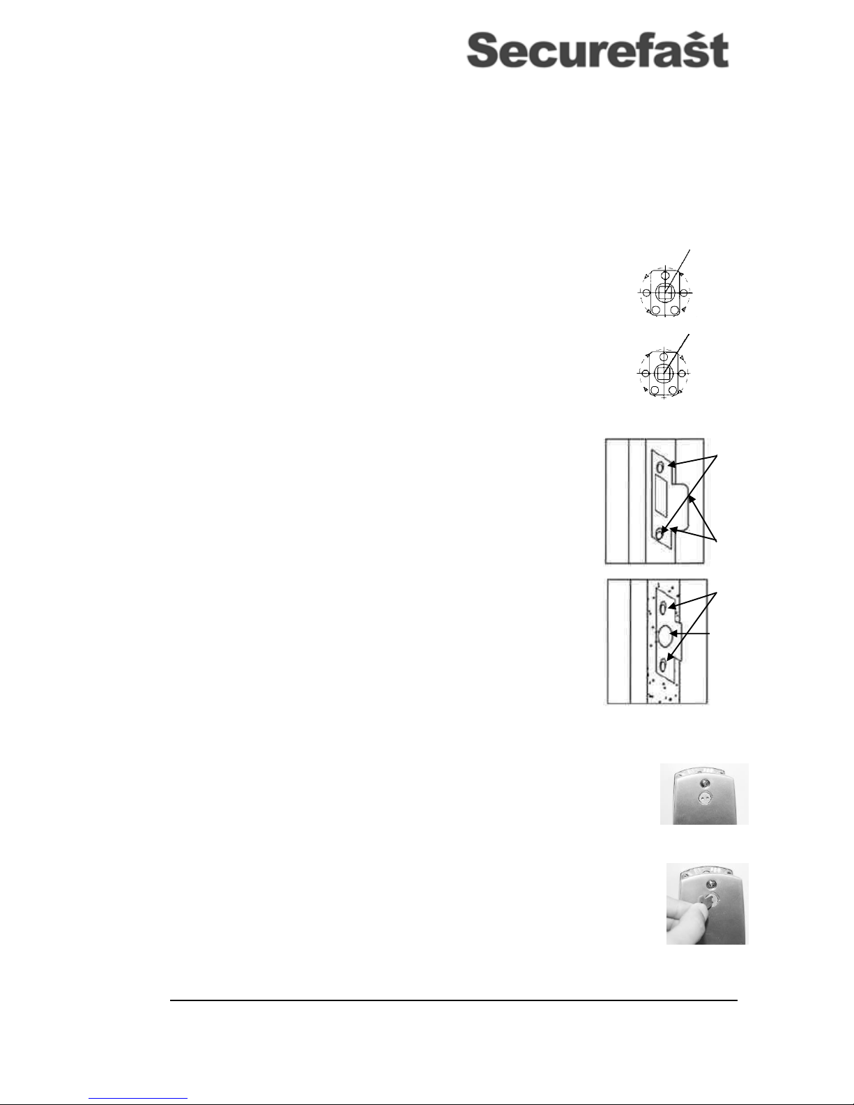
Applying the Template
Position and tape the template (T/051/SBL700), to the internal door face, at the desired height from
the floor level. Ensure that the relevant door edge mark on the template is correctly aligned with
actual door edge. (Figure 1)
Mark the two 7mm holes for the bolt through fixings.
Mark the 12mm diameter hole for the code change metal rod.
Mark all 5mm holes for spindle of digital lock.
Drill all marked holes
Clear the excess material inside the dotted lines surrounding the 5mm holes for spindle of digital lock.
Installing the Latch
Draw a centre line of latch down the edge of the door. (Figure 2)
At the marked position drill a 35mm diameter hole x 85mm deep
Inset Latch into the hole and draw around the face plate.
Remove latch and cut a 3mm rebate to allow the Latch face plate to sit flush in the
door.
Secure latch with wood fixing screws ensuring the positioning is square. If not
square the lock will not function correctly.
Fixing the Lock
Select the appropriate spindle to suit lock follower, shorten if necessary and assemble as
shown in Figure 3.
Feed the radius end of the spindle through the spindle collar and then insert the pin
through the hole in the spindle so it is secure within the collar.
Remove small back plate from the reverse side of Digital Lock, which is held in place by 3
fixing screws.
Locate spindle assembly collar into reverse of Digital Lock and re-secure small back plate
with the 3 fixing screws.
Figure 1
Door edge
Door Thickness
Central point on
‘centre line of
latch’
Door edge
Figure 2
BEFORE INSTALLATION
PLEASE:
1) Ensure all parts work properly
2) Check that a code can be set
and changed by following the
instructions under the ‘Setting
and Changing the Code’
section.
3) Ensure that both knob
handles of the Digital Lock can
be moved freely.
Also check that the latch moves
freely by pressing the end and
by turning with the spindle
LIST OF PARTS
1) Digital Lock with Knob Handle
2) Internal Block
3) Spindle (7mm and 8mm)
4) Fixing Bolts x 3 (1 spare)
5) Spindle Collar
6) Lock Pin
7) Code Change Key
8) Tubular Latch (60mm Backset)
9) Striker
10) Wood screws x 4 (For securing Latch
and Striker Plate)
Figure 1
Figure 3
T/052A/SBL700
3rd January 2016
SBL700
Cut extruding metal rod, for code change, down to 40mm for a door thickness of 45mm and 50mm for a door thickness of
55mm. (When inserting the rod into the snack eye code change cam of the internal turn ensure the dot of the snack eye
is at 12 o’clock and has not rotated out of position)
Cut the fixing bolts to suit door thickness, allowing at least 4/5 threads to secure the outside Digital Lock.
Position Digital Lock and Internal Block on to door taking care to get spindle positioning correct as explained in
“Positioning of Spindle For Digital Lock” and secure the unit to the door.
Before final tightening ensure the lock is vertical and test mechanism to ensure that it is operating freely.
Do not close the door until you are satisfied the lock is functioning correctly. If you wish to check the installation
of the lock by closing the door at any time always do so standing on the inside of the door.
Positioning of Spindle for Digital Lock
For Left handed applications the spindle should be fully rotated anti-clockwise prior to locating it
in the follower of the Latch.
For Right handed applications the spindle should be fully rotated clockwise prior to locating it in
the follower of the Latch.
Fixing Striker Plate
IMPORTANT: The striker must be positioned so that only the latch itself can enter the aperture
and the anti-thrust must stop on the striker plate itself to maintain its anti-burglar function when the
door is locked.
Correctly position the striker plate, taking the above into consideration.
Once the correct position is determined, draw around the striker plate and mark the two
holes.
Remove the striker and cut a 1mm rebate to allow the striker to sit flush within the door
frame.
If necessary drill or cut a recess, at the correct position of the striker, for the latch to enter
when the door is closed.
Drill the two, marked, holes for securing striker
Fix the striker with one screw first. Test the lock to see if it is latching correctly. If not
proceed with any necessary adjustments before securing completely
If no adjustments are to be made completely secure striker with second screw.
Setting and Changing the Code
NOTE: Your lock is supplied without a code setting; following the steps below will allow you to set a code.
To change a code, once a code has been set, you must first enter the correct programmed code on the front of the lock
and then proceed to step 1, and commence code change.
1. Decide on a Code of 4 to 8 numbers (Your code will also consist of ‘C’ at the beginning as this
restores the lock and clears any digits which may already have been inputted)
2. Using the code charge key turn the snake eye code change cam from the 12 o’clock position to the 3
o’clock position.
(DO NOT force the cam, if it does not turn with ease press the ‘C’ button to clear any incorrect codes that may have
already been inputted)
3. Once the dot is in the 3 o’clock position enter the desired code beginning with ‘C’
(NOTE: If you make a mistake whilst entering the desired code press the ‘C’ button to clear and start
again)
4. When certain that all digits of the desired code have been pressed, rotate the dot of the code change
cam back to the 12 o’clock position.
5. Test the newly set code to ensure that it withdraws the latch before closing the door. Remember to
press C first when entering code.
CAUTION: DO NOT change the code whilst the Unit is in the passage function as it could damage the internal mechanism.
Drill Pilot Holes
Spindle
Holes to be
marked
Draw around
outline
Cut out or drill a
recess.
Spindle
T/052A/SBL700
3rd January 2016
SBL700
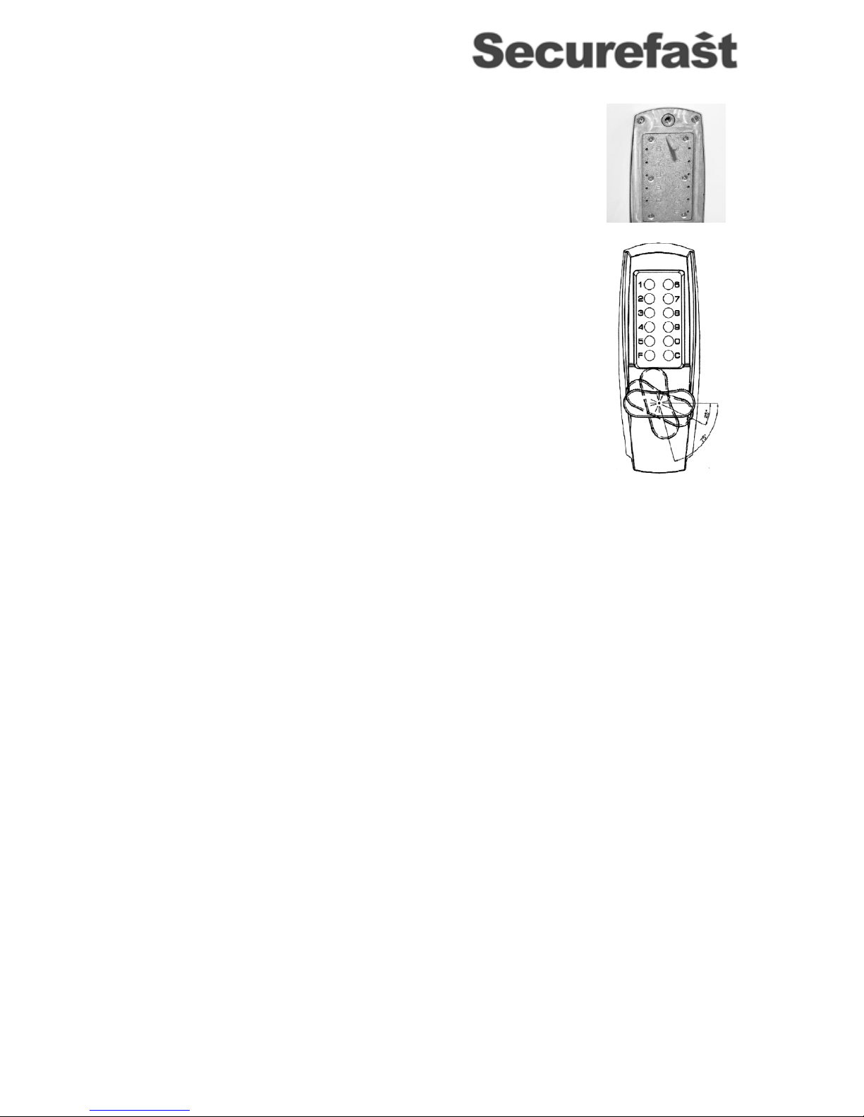
IMPORTANT: If the programmed code is forgotten you can remove the Digital Keypad from the
door and gain knowledge of the programmed code by looking in to the holes on the reverse of the
unit. Press the C button and the holes without any red in them will be the digits programmed into
the lock.
Passage Function
NOTE: When The Passage Function is engaged the outside lever/knob will retract the latch bolt
without the input of the correct code.
To enable the feature follow the steps below:
Enter the correct code
Rotate the handle down to 25-75⁰and push the “F” button
Return the handle to the horizontal position and release the “F” button
To cancel Free Entry Mode:
Rotate the handle down to 25⁰(at which point you should begin to feel the resistance
in the knob handle) at this position press the “C” until you hear a ‘click’
Release the “C” button and return the handle to the horizontal position
For Technical Help Contact Securefast + 44 (0) 1543 501600
Popular Door Lock manuals by other brands


Kwikset
Kwikset CP/BP 49726 / 02 Quick installation guide

Vicenza Designs
Vicenza Designs DHPA8000 Instructions for installation

Aqara
Aqara N100 user manual

Glutz
Glutz 5311 quick start guide

Assa Abloy
Assa Abloy Sargent PE8300 Series installation instructions

Assa Abloy
Assa Abloy HES 9400 Installation Instructions and Frame Preparation