Seenergy SVR-104 User manual

4 Channel
Network Video Recorder
User’s Manual v1.5.3

4 Channel
Network Video Recorder
User’s Manual
English
2
Table of Contents
Copyrights & Trademarks 3
System Requirements 4
Product Description 5
Hardware Illustration 6
LEDs and Buttons 7
Hard Drive Installation 9
Connect to the NVR 10
1. Live View 14
1.1 Retrieve camera’s video stream 15
1.2 Retrieve camera’s status 15
1.3 Perform Sequence Viewing 16
1.4 PTZ Control 17
1.5 Perform PTZ Preset Viewing 18
1.6 Live Video Control Buttons 20
1.7 Change Web UI Display Language 23
2. Playback 24
2.1 Methods to Search Playback Videos 25
2.2 Export Playback Videos to AVI Files 31
2.3 Play Exported AVI Videos With NVR Media Player 33
2.4 Open Event Snapshot Images with NVR Media Player 34
3. System Setup 35
3.1SystemCongurations 35
3.1.1 Network Settings 35
3.1.2 Time and Date 37
3.1.3 User Account 38
3.1.4 Group Privilege 39
3.1.5 Disk Setup 41
3.2ChannelCongurations42
3.2.1 Add a Camera 42
3.2.2 OSD Settings 45
3.2.3 PTZ Preset Settings 46
3.2.4 PTZ Preset Sequence 48
3.2.5 E-Map Setting 49
3.2.5.1 Local Map Setting 51
3.2.5.2 Google Map Setting 52
3.3EventCongurations 53
3.3.1 General Settings 53
3.3.2 Event Servers 55
3.3.3 Event Triggers 59
3.4RecordingCongurations 61
3.4.1 General Settings 61
3.4.2 Schedule Recording 63
3.5 System Options 65
3.5.1 Device Information 65
3.5.2 Logs and Reports 66
3.5.3 Maintenance 66
Reboot the NVR 67
Reset the NVR to Factory Default 68
3.5.4 Disk Status 69

4 Channel
Network Video Recorder
User’s Manual
English
3
Copyright
SEEnergy Corp © 2008
Trademarks
SEEnergy SVR-104 Basic Network Video Recorder is a registered
trademark of SEEnergy Corp.
Microsoft and Windows are registered trademarks of Microsoft Corpo-
ration.
All other trademarks mentioned in this document are trademarks of
their respective owners.
Disclaimer
This document is intended for general information purposes only, and
due care has been taken in its preparation.
Any risk arising from the use of this information rests with the recipi-
ent, and nothing herein should be construed as constituting any kind
of warranty.
SEEnergyreservestherighttomakeadjustmentswithoutpriornoti-
cation.
All names of people and organizations used in this documentís ex-
amplesarectitious.Anyresemblancetoanyactualorganizationor
person, living or dead, is purely coincidental and unintended.
Copyrights & Trademarks

4 Channel
Network Video Recorder
User’s Manual
English
4
System Requirements
The following are minimum system requirements for the system to op-
erate Embedded Network Video Recorder (ENVR):
Operating System
Microsoft® Windows® 2000 Professional, Windows® XP Professional
(32 bit) or Windows® Server 2003 (32 bit)
Browser
Microsoft Internet Explorer 6 or above
CPU
Minimum Intel® Pentium® 4 2.4 GHz or higher (Dual Core is recom-
mended)
RAM
Minimum 1 GB of RAM, 2GB or above is recommended
Network
Minimum 10/100 Ethernet (Gigabit Ethernet is recommended)
Graphics Adapter
AGP or PCI-Express, minimum 1024×768, 16 bit colors.
(We highly recommend to work above the 1024 x 768 resolution to get
the full experience of the software)
• Make sure your display DPI setting is set to default at 96DPI
• To set DPI value, right-click on desktop, choose “Settings” tab >> “Ad-
vanced” >> “General”
Contents Inside the Installation CD
• Adobe Acrobat Reader
• NVR Search Utility
• User’s Manual
• Quick installation Guide
• Datasheet

4 Channel
Network Video Recorder
User’s Manual
English
5
Product Description
The SEEnergy SVR-104 Basic is designed for use within a surveillance
system, and performs recordings and playbacks pictures from net-
work cameras in the system. It is designed for small scale applica-
tions such as retail store. Up to 4 cameras can be connected via a net-
work and it is possible to record their camera pictures. It is possible
to perform the settings or operate the NVR using a web browser in-
stalled on a PC connected to a network and live videos can be viewed
on major mobile devices through its web browser. Recorded video can
be played back from remote site by a PC. SVR-104 Basic is compatible
with most major brand cameras and its ability to automatically search
andndtheavailablecamerasonthenetworkcangreatlyreducethe
user’s effort when confguring the system.
• Two-way Audio
• SEEnergy Smart Camera Search
• Mobile Devices Remote Monitoring
• Pure Web Based Administration
• Manage up to 4 Network Cameras
• Compatible with Major Brand Cameras
• High Quality Live/Playback Video
• Export Playback Videos to AVI

4 Channel
Network Video Recorder
User’s Manual
English
6
Hardware Illustration
(Manual Recording)

4 Channel
Network Video Recorder
User’s Manual
English
7
LEDs and Buttons
Power Button: (Blue when ON) Press to turn on/off the system
Front LEDs:
OS LED
Solid green: System ready
Off: System Off
Blinking:
1. System shutting down
2. Upgradingrmware
a) Through USB drive: Blinking indicating the upgrade is in pro-
cess.Oncermwareupgradecompletes,theLEDgoesoff.Manuallyturn
off the power and turn it back on would be required afterwards.
b) Through the web UI: Blinking indicating the upgrade is in pro-
cess.Oncermwareupgradecompletes,theLEDgoesoff.TheNVRwill
thenrestartautomatically.Onceitnishesrestarting,theLEDshouldturn
to solid green to indicate the system is now ready.
3. Restoringpreviouslysavedcongurationle
a) Through USB drive: The LED should blink to indicate the process
has started. The LED will then go off to indicate the process is complete.
Manually turn off the power and turn it back on would be required after-
wards.
b) Through Web UI: The LED should blink to indicate the process
has started. The LED will then go off to indicate the restoring is complete
and the system is restarting. The OS LED should indicate in solid green
once the system becomes ready.
Recording LED
Solid amber: recording
Off: not recording
Blinking: Manual recording:
When “manual recording button” is pressed
* To start manual recording with the “manual recording button”, press and hold
the button for 2 seconds then release it. Follow the same procedure to stop.
4 Channel
Network Video Recorder
User’s Manual
English
8
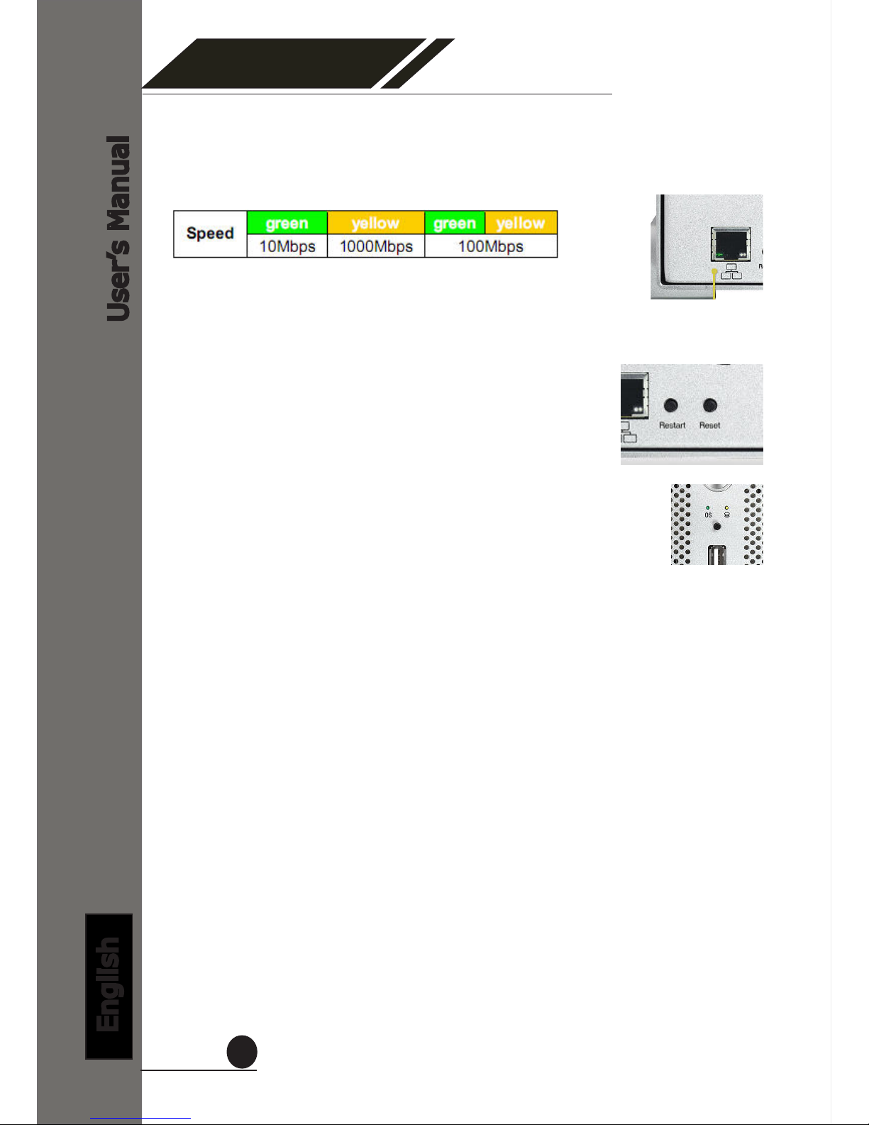
Restart Button
Press and release the button for hardware re-
start. The OS LED should should go off during the
restart to indicate the system is restarting. The
LED should indicate in solid green once the sys-
tem becomes ready.
Reset Button
Press this button will restore the system’s set-
tings to factory default values. To start, press and
hold the button for 5 seconds then release it once
the OS LED goes off. The OS LED should indicate
in solid green once the system becomes ready.
Ethernet Port LED
The green LED on the left indicates the link connection and the LED on the
right indicates the speed

4 Channel
Network Video Recorder
User’s Manual
English
9
Hard Drive Installations
1. Remove the four screws
from the bottom of the case.
2. Push the inner enclosure
out, and remove the outer
chassis.
3.Installtherstharddrive
by placing it in the enclosure
and connecting the SATA plus
power cables.
4. Mount the drive with two
screws on each side.
5. Attach the thermal probe
with the tape provided to the
rstharddrive.
Choose a location in between
the two drives but without
damaging the thermal probe
when installing the second
drive.
6. Install the second hard drive
by placing it in the enclosure
and connecting the SATA plus
power cables.

4 Channel
Network Video Recorder
User’s Manual
English
10
Connect to the NVR
There are various ways you can connect to the NVR and below are
the suggested methods for different network setup:
• The NVR is placed in a network with a DHCP server: Connect to
the NVR by using “NVR Search” Utility
• The NVR is placed in a network without DHCP server (or you are
connecting to it directly): Access NVR with its default IP
Use NVR Search Utility
To begin, launch the “NVR Search” utility from the CD and proceed
with the installation:
If the NVR is placed in a corporate network or a local area network
where a DHCP server is already presented, run the “NVR Device
Search” utility from a computer that is on the same network (within
the same subnet) and locate the NVR with its IP address that is as-
signed by the top-level DHCP server.

4 Channel
Network Video Recorder
User’s Manual
English
11
Once the installation is complete, check the “Launch the Search AP”
option and click “Finish”:
The search should start automatically and its status should be dis-
played:
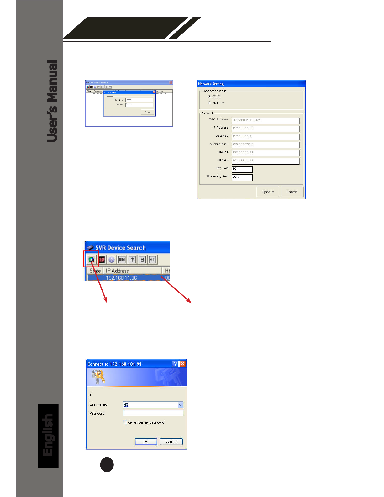
The NVR should be located and its IP address should be displayed:
Double-click on it and the program should automatically access the
NVR’s web administration page from your default browser
You may change NVR’s IP address by click on the button highlighted
below.
4 Channel
Network Video Recorder
User’s Manual
English
12
You should be prompted for the NVR’s username and password. En-
ter its default username “admin” and password “admin” and then
click”OK” to enter the system
You will be prompted for the NVR’s login information before proceeding
to change device’s IP address.
You may click on the button highlighted below to perform search again.
Or double-click on any of the search results to access NVR’s web ad-
ministration page
perform search again access NVR’s web administration page

4 Channel
Network Video Recorder
User’s Manual
English
13
* The built-in DHCP server is intended to ease the installation between
the NVR and the IP cameras. In the event there’s no DHCP server (router)
presented in the network, the NVR can act as DHCP server and assign IP
to cameras.
However, if such conguration method is chosen, it’s strongly suggested
that the NVR is fully started rst as startup time is different among differ-
ent network devices.
Due to the reason that the IP cameras tend to nish booting up faster than
the NVR, if the NVR is not fully started before IP cameras do, there is a very
great chance that the cameras will not properly obtain IPs from the NVR.
In the event that users wish to setup everything on the network with static
IP addresses, the built-in DHCP server function can be manually turned off
under “Setup” >> “System Conguration” >> “Network Setup” and check
off the DHCP server function.
4 Channel
Network Video Recorder
User’s Manual
English
14
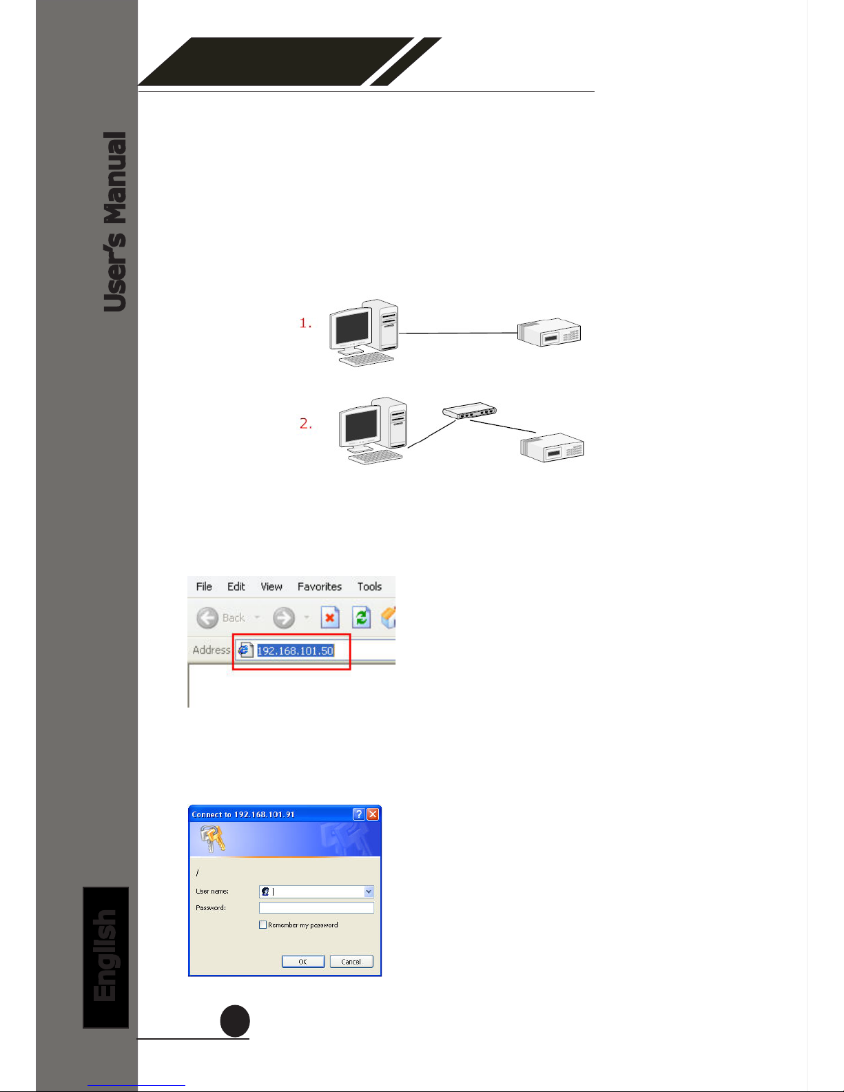
TheNVRcomeswithapre-conguredstaticIP“192.168.101.50”.
However, it is only used when there is no DHCP server presented in
the network. The NVR will turn on its DHCP server function and act
as the DHCP server in the network. To connect to the NVR, use a PC
that is on the same network over a switch or hub, or connect the PC
directly to the NVR using a crossover CAT5 Ethernet cable.
The PC that is connected directly to the NVR (or within the same local
area network) should receive an IP from it. Simply access the NVR
from your web browser with its IP address
Again, you should be prompted for the username and password. En-
ter its default username “admin” and password “admin” and then
click”OK” to enter the system
Access NVR with its default IP address

4 Channel
Network Video Recorder
User’s Manual
English
15
The “Live View” page provides the following functions:
• Retrieve camera’s video stream
• Retrieve camera’s status
• Perform Live Sequence Viewing
• PTZ Control
• Perform PTZ Preset Sequence viewing
• Perform manual recording
• Take snapshot
• Receive audio of a video stream
• Send audio
• Change web UI display language
1. Live View

4 Channel
Network Video Recorder
User’s Manual
English
16
1.1 Retrieve camera’s video stream
The camera list is expanded and dis-
played on the Live View page.
• Click “All” to display videos in the
quad-video mode
• Click on any camera to display
video in single-view mode
1.2 Retrieve camera’s status
The camera list can show each camera’s current status. Each sta-
tus is represented with different colors and their meanings are ex-
plained on the left
Camera is connected
Camera is NOT connected
Camera is current performing recording

4 Channel
Network Video Recorder
User’s Manual
English
17
1.3 Perform Sequence Viewing
Sequence view is a function that allows you to view multiple vid-
eo streams from certain cameras in sequence automatically without
having to select them one by one.
To perform sequence view, select “SEQ View” from the upper-left
hand corner
Next, select one or more camera(s) or camera group(s) for sequence
viewing
Then select dwell interval from the drop-down menu
Finally click “Start” to start sequence viewing
* Click “All Channels” to quickly select all available channels and start sequence
view in single-view mode.

4 Channel
Network Video Recorder
User’s Manual
English
18
1.4 PTZ Control
PTZ control provides functions to pan, tilt, zoom a PTZ camera
as well as the ability to adjust camera focus and iris
Camera(s) that are currently being selected for live viewing will
be listed in the PTZ drop-down menu. Simply select a camera
then use the PTZ control panel to control the camera
The bar shown below allows you to control the pan/tilt speed

4 Channel
Network Video Recorder
User’s Manual
English
19
1.5 Perform PTZ Preset Viewing
There are three functions provided in the “Preset” section:
• Perform preset point viewing of a particular camera
• Auto pan a particular camera
• Perform preset point sequence viewing
Start by selecting a PTZ camera from the drop-down list:
Its available PTZ preset points will be listed in the drop-
down list shown below:
Select a preset position from the drop-down list and click
“Go to” to move the live view to that position
Preset Point Viewing

4 Channel
Network Video Recorder
User’s Manual
English
20
Auto Pan Viewing
Start by selecting a PTZ camera from the drop-down list:
Use the Auto Pan control buttons to pan right, left and
stop auto pan
Pan Left
Pan right
Stop pan
Preset Point Sequence Viewing
This function allows you to view multiple preset points
from a video of a camera without having to select them
onebyone.Onceyouhavedenedthepreferedpreset
points in “ChannelCongurations” >> “PTZ Setting”
>> “PTZ Sequence” under the “Setup” menu, click
“Start” in the lower-left hand corner in Live View under
“Preset” and the recorder will begin to display videos from
those preset points in sequence automatically until you
click “Stop”
Autopan
* Certain cameras do not support
bi-directional pan movements.
Use the “Autopan” button for
such cameras
“In the Setup page” In the Live View
Other manuals for SVR-104
2
This manual suits for next models
1
Table of contents
Other Seenergy Network Hardware manuals

Seenergy
Seenergy SVR-104 User manual

Seenergy
Seenergy SVR-204 User manual

Seenergy
Seenergy SVR-808e User manual

Seenergy
Seenergy SVR-104 User manual

Seenergy
Seenergy SVR-116 Plus User manual

Seenergy
Seenergy SVR-816 User manual

Seenergy
Seenergy SVR-504 User manual

Seenergy
Seenergy SVR-632/664 User manual

Seenergy
Seenergy SVR-204 User manual

Seenergy
Seenergy SVR-816 User manual


