Seenergy SVR-504 User manual
Network Video Recorder
Model: SVR-504/508/516/516+
User’s Manual v1.0.0

SVR-500 Series
Network Video Recorder
Quick Guide
English
2
Table of Contents
Product Description 6
Install Hard Disk 7
Hardware Illustration 10
I/O Ports and RS-485 12
LEDs Denition 13
Connect to the NVR 15

SVR-500 Series
Network Video Recorder
Quick Guide
English
3

SVR-500 Series
Network Video Recorder
Quick Guide
English
4
Copyright
SEEnergy Corp © 2012
Trademarks
SEEnergy SVR-500 Series (SVR-504/508/516/516+) Network Video
Recorder (NVR) is a registered trademark of SEEnergy Corp.
Microsoft and Windows are registered trademarks of Microsoft Corpo-
ration.
All other trademarks mentioned in this document are trademarks of
their respective owners.
Disclaimer
This document is intended for general information purposes only, and
due care has been taken in its preparation.
Any risk arising from the use of this information rests with the recipi-
ent, and nothing herein should be construed as constituting any kind
of warranty.
SEEnergy reserves the right to make adjustments without prior noti-
cation.
All names of people and organizations used in this documentís ex-
amples are ctitious. Any resemblance to any actual organization or
person, living or dead, is purely coincidental and unintended.
Copyrights & Trademarks

SVR-500 Series
Network Video Recorder
Quick Guide
English
5
System Requirements
The following are minimum system requirements for the system to op-
erate Embedded Network Video Recorder (ENVR):
Operating System
Microsoft® Windows® XP Professional SP2, Windows Vista, Windows 7,
Windows® 2003 Server, or Windows® 2008 Server
Browser
Microsoft Internet Explorer 7 or above
CPU
Minimum Intel® Pentium® 4 2.4 GHz or higher (Dual Core is recom-
mended)
RAM
Minimum 1 GB of RAM, 2GB or above is recommended
Network
Minimum 10/100 Ethernet (Gigabit Ethernet is recommended)
Graphics Adapter
AGP or PCI-Express, minimum 1024×768, 16 bit colors.
(We highly recommend to work above the 1024 x 768 resolution to get
the full experience of the software)
• Make sure your display DPI setting is set to default at 96DPI
• To set DPI value, right-click on desktop, choose “Settings” tab >> “Ad-
vanced” >> “General”
Contents Inside the Installation CD
• Adobe Acrobat Reader
• Smart Device Search Utility
• Pi-Vu Central Basic CMS software
• NVR Media Player
• User’s Manual
• Quick installation Guide
• Datasheet

SVR-500 Series
Network Video Recorder
Quick Guide
English
6
Product Description
The Embedded Network Video Recorder is designed for use within a
surveillance system, and performs recordings and playbacks pictures
from network cameras in the system. It is a recording device using a
hard disk drive to record camera pictures instead of using video tapes
so that pictures recorded by repeated overwriting will not experience
deterioration of the recorded picture quality. Up to 4 (for SVR-504) or 8
(for SVR-508) or 16 (for SVR-516) cameras can be connected via a net-
work and it is possible to record their camera pictures. It is possible to
perform the settings or operate the NVR using a web browser installed
on a PC connected to a network, or remote controller. Recorded video
can be played back from remote site by a PC. Up to 4 PCs (web brows-
ers) can access this unit concurrently and it is possible to perform the
settings and operate this unit. The NVR is compatible with most major
brand cameras and its ability to automatically search and fnd the
available cameras on the network can greatly reduce the user effort
when expanding the system.
• Export Recorded Videos to AVI
• Compatible with Major Brand Cameras
• High Quality Live/Playback Videos
• Smart Camera Search
• Support UPS System
• Advance PTZ Control
• Various Types Event Alerts
• Pure Web Based Administration
• Linux-embedded Operating System
• Support Dual Stream

SVR-500 Series
Network Video Recorder
Quick Guide
English
7
Install Hard Disk
Start by removing the screws on the side:
Push the top housing forward.
Then lift it up.
• TheNVRsupportsSATAIor
SATAIIharddisks.
• TheNVRsupportsmax.3TBper
harddiskanditsupportstotalof
2harddisks(6TB).
SVR-500 Series
Network Video Recorder
Quick Guide
English
8
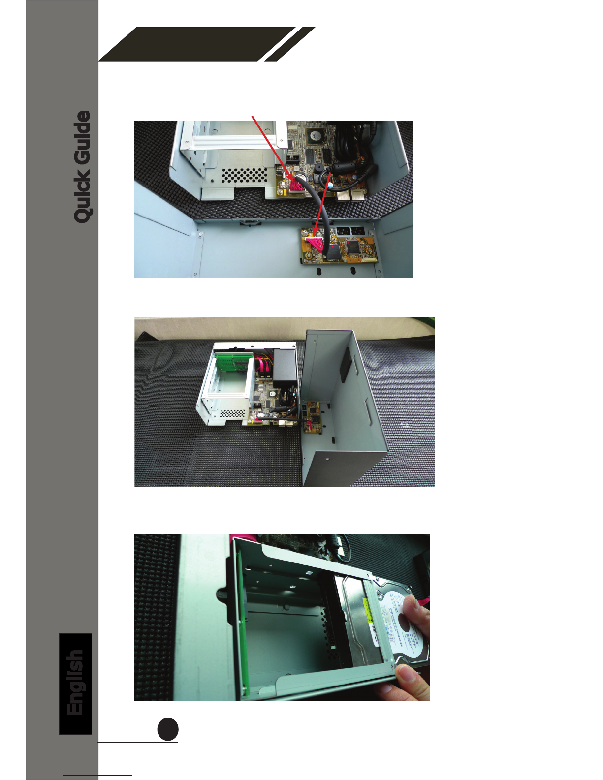
There is a cable connected between the fron LED board and the main
board.
You can remove it from the main board or simply put the top housing on
the side like shown below.
Next, slide the hard drive into the tray.

SVR-500 Series
Network Video Recorder
Quick Guide
English
9
Make sure the SATA connectors are correctly aligned with each other.
Secure the hard drive with the tool-less screw provided in the box.
Place the top housing back and secure it with the bottom housing.
SVR-500 Series
Network Video Recorder
Quick Guide
English
10
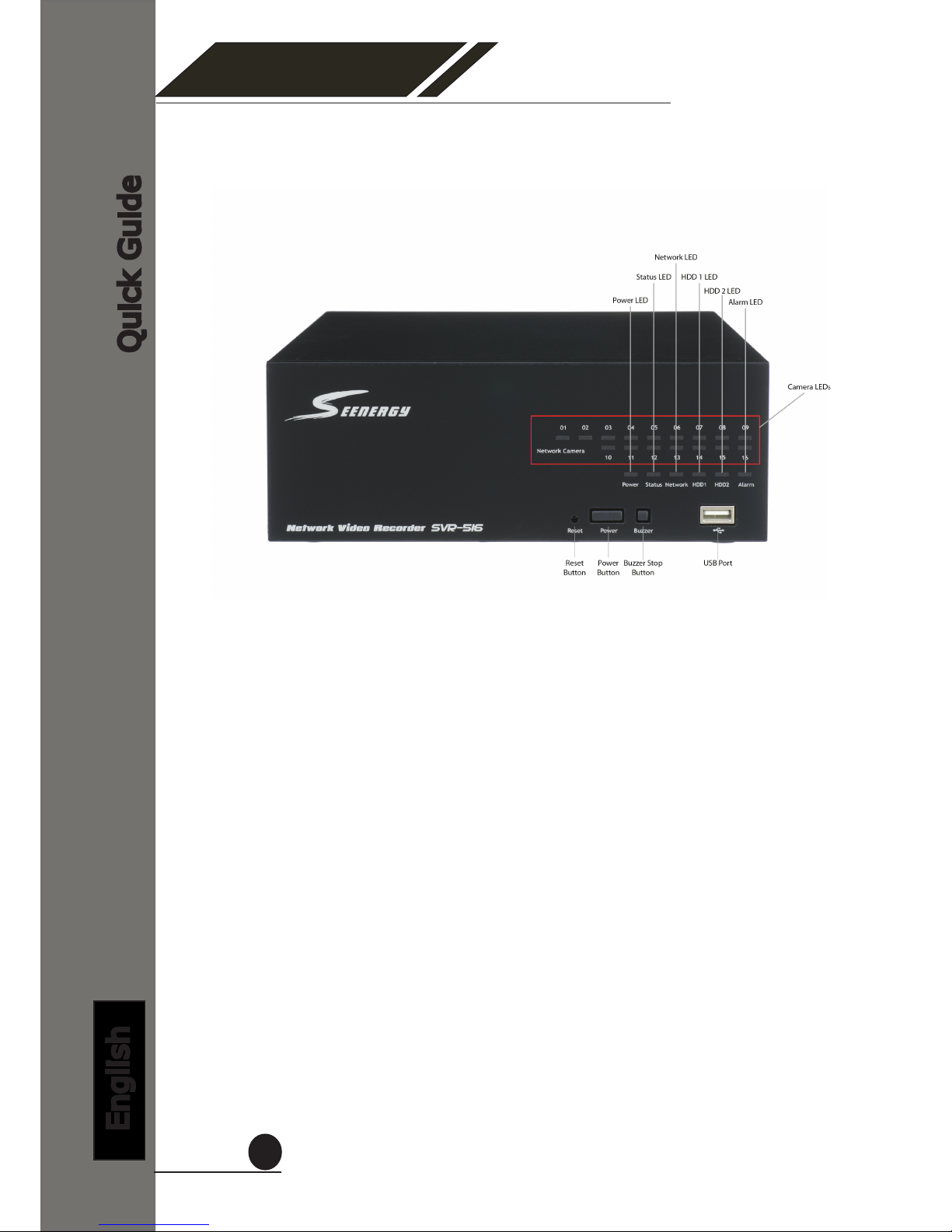
Hardware Illustration (Front)

SVR-500 Series
Network Video Recorder
Quick Guide
English
11
LEDs Denition
HDD x 2
Green Solid green when the hard disk is mounted
and being accessed.
Red Solid red for disk fail.
Amber Solid amber when recording is in process.
Blinking when recycling.
Network
Amber Solid amber for activity on a 1G bps network.
Green Solid green for activity on a 10/100 Mbps
network.
Status
Amber Blinking during rmware upgrade.
Green
Shows solid green for normal operation.
Blinking green when rmware upgrade is
done.
Red Flashes red for failed rmware upgrade.
Power
Green Normal operation.
Red System off (power adapter remains plugged
in).
Amber Blinking amber indicating device is initializing.
Alarm Red Blinking when an alarm occurs.
None When alarm is reset.
Camera
LED
Green Solid green, live connected with no event or
recording activity.
Amber Blinking amber, manual or event recording is
being performed.
Amber Solid amber, schedule or continuous recording
is being performed.
Red Recording is set but no video from camera.
SVR-500 Series
Network Video Recorder
Quick Guide
English
12
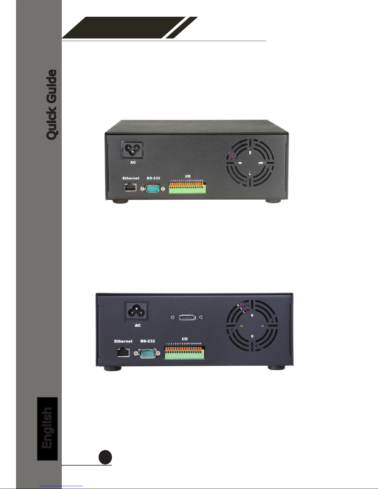
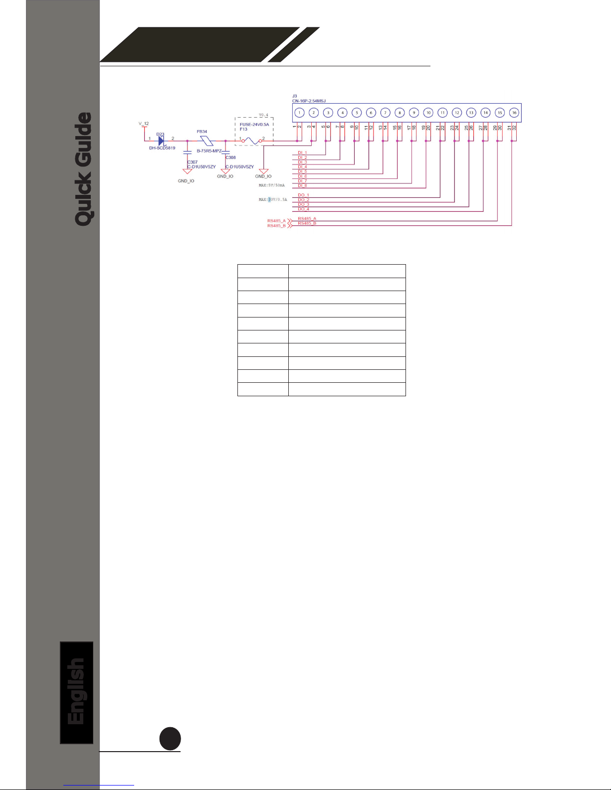
I/O Ports and RS-485 (Rear)
SVR-504/508/516
SVR-516+
SVR-500 Series
Network Video Recorder
Quick Guide
English
13
Pin Signal
1 12V DC
2 GND
3~10 Alarm input
11 Out1
12 Out2
13 Out3
14 Out4
15 RS485+
16 RS485-
SVR-500 Series
Network Video Recorder
Quick Guide
English
14
Connect to the NVR
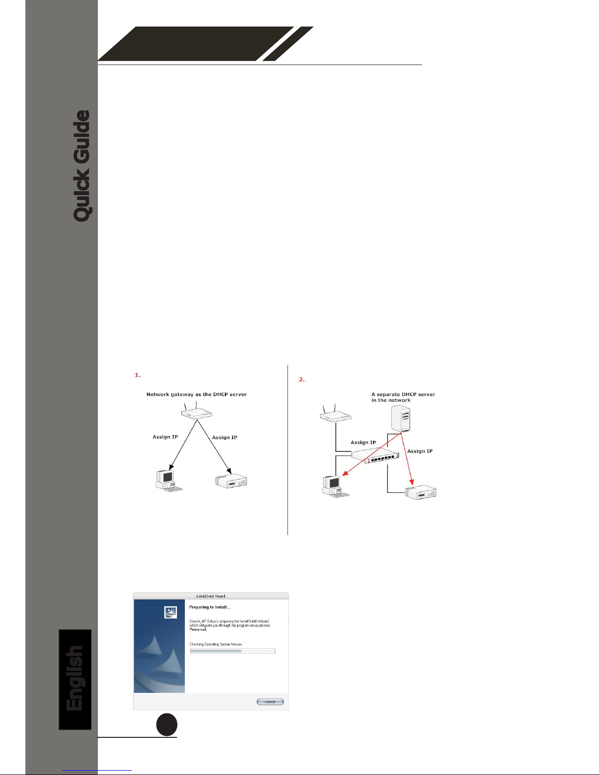
There are various ways you can connect to the NVR and below are
the suggested methods for different network setup:
• The NVR is placed in a network with a DHCP server: Connect to
the NVR by using “SEEnergy Device Search” Utility
• The NVR is placed in a network without DHCP server (or you are
connecting to it directly): Access NVR with its default IP
Use SEEnergy Device Search Utility
When the NVR is on a corporate network, or a local area network
where a DHCP server is already present. Run the “SEEnergy Device
Search” utility from a computer which is also on the same network
and locate the NVR via its IP address assigned by the top-level DHCP
server.
To begin, launch the “SEEnergy Device Search” utility from the CD
and proceed with the installation:

SVR-500 Series
Network Video Recorder
Quick Guide
English
15
Once the installation is complete, check the “Launch the Search AP”
option and click “Finish”:
The search should start automatically and its status should be dis-
played:
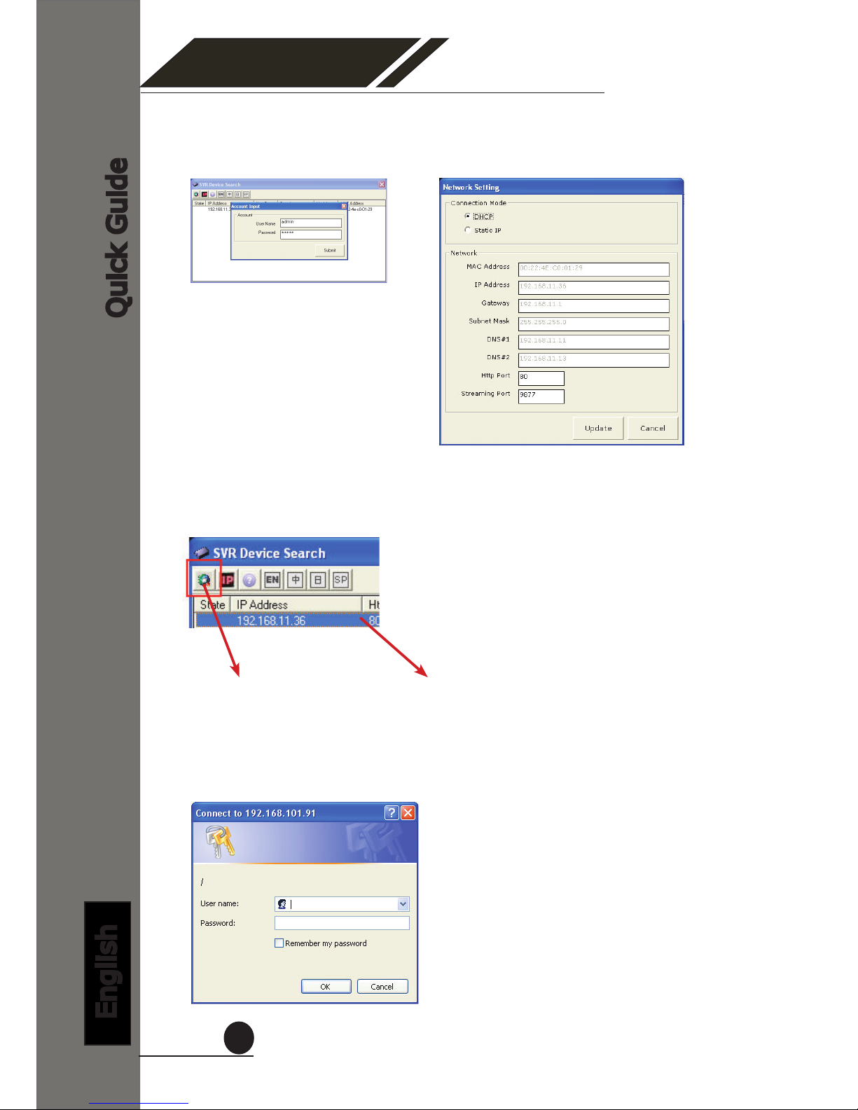
The NVR should be located and its IP address should be displayed:
Double-click on it and the program should automatically access the
NVR’s web administration page from your default browser
You may change NVR’s IP address by click on the button highlighted
below.
SVR-500 Series
Network Video Recorder
Quick Guide
English
16
You should be prompted for the NVR’s username and password. En-
ter its default username “admin” and password “admin” and then
click”OK” to enter the system
You will be prompted for the NVR’s login information before proceeding
to change device’s IP address.
You may click on the button highlighted below to perform search again.
Or double-click on any of the search results to access NVR’s web ad-
ministration page
perform search again access NVR’s web administration page

SVR-500 Series
Network Video Recorder
Quick Guide
English
17
The NVR comes with a pre-congured static IP “192.168.101.50”.
However, it is only used when there is no DHCP server presented in
the network. The NVR will turn on its DHCP server function and act
as the DHCP server in the network. To connect to the NVR, use a PC
that is on the same network over a switch or hub, or connect the PC
directly to the NVR using a crossover CAT5 Ethernet cable.
The PC that is connected directly to the NVR (or within the same local
area network) should receive an IP from it. Simply access the NVR
from your web browser with its IP address
Again, you should be prompted for the username and password. En-
ter its default username “admin” and password “admin” and then
click”OK” to enter the system
Access NVR with its default IP address

SVR-500 Series
Network Video Recorder
Quick Guide
English
18
Connecting Digital Vision
SEEnergy Corp.
4F, No.61, Dongsing RD.,
Taipei 110, Taiwan, R.O.C.
Tel: 886-2-8768-1518
Fax: 886-2-8787-8560
E-mail: sales@seenergy.com.tw
www.seenergy.com.tw
©2007, SEEnergy Corp. The SEEnergy logo is a registered trademark of SEEnergy Corp. All other company names and products
are trademarks or registered trademarks of their respective companies. The specication is subject to change without prior notice.
SEEnergy endeavors to ensure that the information in this document is correct and faily stated but does not accept liability for any
error or omissions.
EN/M100/03012012/001
Other manuals for SVR-504
1
This manual suits for next models
3
Table of contents
Other Seenergy Network Hardware manuals

Seenergy
Seenergy SVR-816 User manual

Seenergy
Seenergy SVR-304 Basic User manual

Seenergy
Seenergy SVR-808e User manual

Seenergy
Seenergy SVR-204 User manual

Seenergy
Seenergy SVR-104 User manual

Seenergy
Seenergy NVR-304 Basic User manual

Seenergy
Seenergy SVR-116 Plus User manual

Seenergy
Seenergy SVR-632/664 User manual

Seenergy
Seenergy SVR-204 User manual

Seenergy
Seenergy SVR-104 User manual


