Seiko 4R15A Quick start guide

PARTS LIST /TECHNICAL GUIDE
Automatic Cal. 4R15A/4R15B/4R16A/4R16B
[SPECIFICATIONS]
1/19
Item Cal. No. 4R15A/4R15B/4R16A/4R16B
22 jewels
Automatic winding
Between -35 and +45 seconds
Automatic winding function
* Day and date correction function
*Day and date correction
Time setting (Hour and minute)
Free
Measurement
(daily rate in
Movement
[Bridge side] [Calendar side]
Movement size
53 °
Daily rate worn
5 °C and 35 °C)
Standard rate
for measure-
ment
T24 (CH)
from fully wind
Driving system
Additional function
Crown operation
Loss/Gain
Regulation system
Number of jewels
Lift angle of the escapment
Vibration per hour
Continuous operating time

SPECIFICATIONS
2/19
Cal. 4R15A/4R15B/4R16A/4R16B
FEATURES
CHARACTERISTICS OF A MECHANICAL WATCH

PARTS LIST Cal. 4R15A/4R15B/4R16A/4R16B
3/19
PARTS DIFFERENCES BETWEEN A SERIES AND B SERIES
4R15A
4R15B
B
5
DATE DISK (4R15) *
- -
DATE DISK (4R15) *
-
-
DATE DISK (4R15) *
-
-
- -
- -
9
12
13
35
45 -
54
55

Cal. 4R15A/4R15B/4R16A/4R16B
PARTS LIST
4/19
0963300
SNAP FOR DAY DISK
0160***
2
DAY DISK WITH DAY STAR
0989070
3
DAY CORRECTOR WHEEL
0012354
4
DATE DISK GUARD
SCREW A (3pcs)
CAL A: 0016705
CAL B: 0012354
5
DATE DISK GUARD SCREW B (1 pce)
CAL A: 0808300
CAL B: 0808310
6
DATE DISK GUARD
7DATE DISK
CAL A: 0810030
CAL B: 0810183
8
DATE JUMPER
CAL A: 0737300
CAL B: 0737183
9
CALENDAR CORRECTOR
SLIDNG INTERMEDIATE
WHEEL
CAL A: 0271483
CAL B: 0273183
10
HOUR WHEEL
0817300
11 INTERMEDIATE DATE
WHEEL
CAL A: 0802300
CAL B: 0802183
12
DATE DRIVING WHEEL
13
MINUTE WHEEL
0225005
CANNON PINION
4408170
14
HOLDING RING FOR DIAL
0012420
LOWER BRIDGE FOR THIRD
WHEEL SCREW
CAL A: 0436300
CAL B: 0436183
16
LOWER BRIDGE FOR THIRD
WHEEL
1
SHOCK ABSORBER
17 0014577
SHOCK ABSORBING
SPRING
0011220
SHOCK ABSORBING CAP
JEWEL
19 0014295
HOLE JEWEL FRAME FOR
SHOCK ABSORER
50 -2
15
18
0878*** or 0148***
CAL A: 0267006
CAL B: 0261183
[CALENDAR MECHANISM]
214

PARTS LIST Cal. 4R15A/4R15B/4R16A/4R16B
5/19
[BALANCE AND ESCAPEMENT] [WINDING MECHANISM (1)]
BALANCE COCK
SCREW
0012420
BALANCE COCK WITH
REGULATOR
0171197
BALANCE COMPLETE
0310197
PALLET COCK SCREW
0012354
PALLET COCK
0161302
PALLET FORK
0301009
OSCILLATING WEIGHT
CAL A: 0436300
CAL B: 0436183
SECOND REDUCTION
WHEEL SCREW
0012539
RACHET WHEEL SCREW
0012919
RACHET WHEEL
0285051
SECOND REDUCTION
WHEEL
0514002
29
30
31
32
33
21
22
23
24
20
SHOCK ABSORBER
25 0014577
SHOCK ABSORBING SPRING
0011220
SHOCK ABSORBING CAP
JEWEL
27 0014295
HOLE JEWEL FRAME
FOR SHOCK ABSORER
26
28

Cal. 4R15A/4R15B/4R16A/4R16B
PARTS LIST
CLICK
0381004
FOURTH WHEEL
0241010
BARREL COMPLETE
(WITH MAINSPRING)
CAL A: 0201267
CAL B: 0201164
THIRD WHEEL
0231007
ESCAPE WHEEL
0251013
CENTER WHEEL BRIDGE
SCREW
0012354
CENTER WHEEL BRIDGE
0122302
CENTER WHEEL WITH
CANNON PINION
CAL A: 0224086
CAL B: 0224183
SETTING LEVER JUMPER
SCREW
0012168
SETTING LEVER JUMPER
0388177
YOKE
0384070
SETTING LEVER
CAL A: 0383070
CAL B: 0383178
CLUTCH WHEEL
CALENDAR CORRECTOR
1ST INTERMEDIATE WHEEL
0962008
SETTING STEM
0351***
BARREL AND TRAIN WHEEL
0012420
BRIDGE SCREW
BARREL AND TRAIN WHEEL
BRIDGE
CAL A: 0112388
CAL B: 0114178
FIRST REDUCTION
WHEEL
0511010
PAWL LEVER
CAL A: 0831077
CAL B: 0831183
FIRST REDUCTION WHEEL
HOLDER
0836002
MAIN PLATE
CAL A: 0100326
CAL B: 0104181
36
48
43
47
49
50
52
53
54
55
56
57
58
37
38
34
35
41
42
39
40
HOLD SPRING FOR
ESCAPE WHEEL
0015703
CAP JEWEL FOR ESCAPE WHEEL
0011220
HOLD SPRING FOR
THIRD WHEEL
0015703
CAP JEWEL FOR THIRD WHEEL
0011220
44
45
50 -1
CENTER WHEEL
0221086
50 -2
CANNON PINION
0225005
CAL A: 0282070
CAL B: 0282183
[WINDING MECHANISM (2), GEAR TRAIN MECHANISM AND SETTING MECHANISM]
refer to

PARTS LIST Cal. 4R15A/4R15B/4R16A/4R16B
REMARKS
14
4408170 4408171
●How to find the correct parts, if not determined by 4 digit caliber number
2

Cal. 4R15A/4R15B/4R16A/4R16B
PARTS LIST
● How to discrimianate resembled parts
0012 919
0012 539
0012 354
0016 705
0012 420
0012 168
21 Second reduction
screw
4 Date dial guard
screw A
34 Barrel and train

PARTS LIST Cal. 4R15A/4R15B/4R16A/4R16B
9/19
Balance
Balance (roller jewel)
Total
22 jewels
Location of the jewels

Cal. 4R15A/4R15B/4R16A/4R16B
PARTS LIST
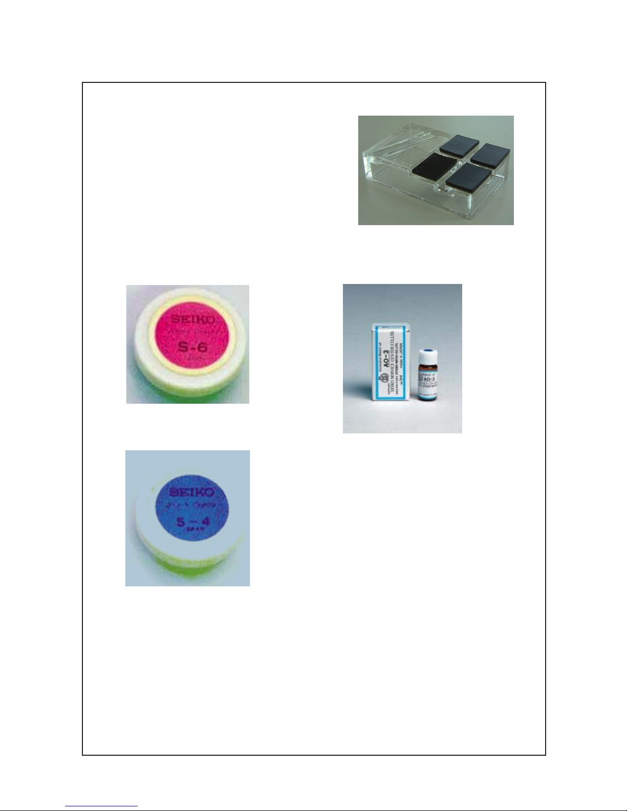
●Tools and consumables required for disassembling/reassembling
• MoveMent holder
• Watch oils
S-4

TECHNICAL GUIDE Cal. 4R15A/4R15B/4R16A/4R16B
11/19
●
How to remove the SETTING STEM before
dismantling the movement
Crown position: NORMAL
Push the SETTING LEVER gently (refer to the picture
on the right) in order to disengage it from the SETTING
STEM.
Then pull out the crown with the stem completely.
* After dismantling the movement from the case,
push back the crown with the SETTING STEM to the
movement.
RemaRks on disassembling and Reassembling the movement

TECHNICAL GUIDE Cal. 4R15A/4R15B/4R16A/4R16B
12/19
● Balance and escapement
How to disassemble/reassemble the BALANCE and BALANCE COCK
• Disassembling
1) Rotate the STUD SUPPORT until it touches to the BALANCE COCK.
When doing so, make sure that the second bend of the balance-spring does not touch the
REGULATOR PIN.
2) Push out the stud parallel to the slit of the STUD SUPPORT (the direction also shown by the red arrow
in the illustration) in order to remove it from the STUD SUPPORT.
3) Unscrew the BALANCE COCK SCREW and remove the BALANCE COCK WITH REGULATOR.
4) Remove the BALANCE COMPLETE WITH STUD.

TECHNICAL GUIDE Cal. 4R15A/4R15B/4R16A/4R16B
13/19
• Reassembling
1) Install the BALANCE COMPLETE WITH STUD to the MAIN PLATE.
2) Set the BALANCE COCK WITH REGURATOR and tighten the BALANCE COCK SCREW.
3) Temporarily set the stud to the STUD SUPPORT.
Do not engage the balance-spring to the REGULATOR PIN. The balance-spring passes outside of the
REGULATOR-PIN at this stage.
4) Push back the stud parallel to the slit of the STUD SUPPORT.
5) Engage the balance-spring with the slit of the REGULATOR PIN.
* When assembling the BALANCE COMPLETE, pay great attention
not to deform the balance-spring, especially at the second
bend.

TECHNICAL GUIDE Cal. 4R15A/4R15B/4R16A/4R16B
14/19
• Lubricating
ws SECOND REDUCTION WHEEL
Lubricate the SECOND REDUCTION WHEEL.
Refer to the right figure.
eh FIRST REDUCTION WHEEL
Liberally lubricate the FIRST REDUCTION WHEEL.
Refer to the right figure.
ek FIRST REDUCTION WHEEL HOLDER
w; OSCILLATING WEIGHT
When fixing the OSCILLATING WEIGHT, an alignment with the FIRST REDUCTION WHEEL is necessary
in order to wind the MAINSPRING most efficiently. Rotate the FIRST REDUCTION WHEEL manually until
its hole aligns with the gilt dot on the BALANCE COCK and set the OSCILLATING WEIGHT vertically at
the stem side, and then tighten the screw. Refer to the figure below.
●Winding mechanism
First reduction wheel
First reduction wheel holder
Barrel and train wheel bridge (back side)
35
>>gnilbmessA<<>>gnilbmessasiD<<
38
36
Balance cock guide pin
First reduction wheel
㻨㼑㼏㼄㼕㼊㼈㼇
㼙㼌㼈㼚

TECHNICAL GUIDE Cal. 4R15A/4R15B/4R16A/4R16B
15/19
REGULATION
●Names of the parts for regulation and their functions
[STUD SUPPORT]
Correction of the beat
error by positioning the
roller jewel correctly
[REGUL ATOR]
Regulation of the accuracy rate (+) or
(-) by adjusting the operative length
of the balance-spring
[STUD (glued at the balance-spring)]
Alignment of the balance-spring to the
center of the regulator pin's slit
[REGULATOR PIN]
Adjustment of the play of the bal-
ance-spring embraced in its slit
●
How to regulate the isochronism fault by adjusting the position of the balance-spring
This caliber has the Etachron system for fine regulation of the isochronism fault, which is the same
design used for both Cal. 7S-B series and 6R series.
When an amplitude of the balance becomes weak, the watch shows time loss, in general.
By making a clearance of the balance-spring smaller, the decline curve of the instantaneous rate
gets shallower.
1) Make sure that the REGURATOR PIN is aligned in a vertical position to the REGURATOR and the
balance-spring passes parallel through the slot of the REGULATOR PIN before fine-tuning the STUD
and the REGULATOR PIN.
REGULATOR PIN
top side view back side view angled view
1
2
3
4
1
2
3
4
2
RegUlation

TECHNICAL GUIDE Cal. 4R15A/4R15B/4R16A/4R16B
16/19
2) Rotate the STUD in order to align the position of the balance-spring passes through the center of the
slot of the REGULATOR PIN.
STUD REGULATOR PIN
3) Rotate the REGULATOR PIN counterclockwise in order to fine-tune the clearance of the balance-spring
passing through the slot of it.
top side view back side view
REGULATOR PIN
top side view
Before rotating After rotating
back side view
Before rotating After rotating
(Maximum clearance) (Minimum clearance)

TECHNICAL GUIDE Cal. 4R15A/4R15B/4R16A/4R16B
17/19
RemaRks on insPeCtion and measURement
Operation Function Checkpoint
Pull out the
crown to the 2nd
click and push it
back in to the
normal
position. Repeat
the same several
times.
Setting mechanism -
switching the
function of the time
setting
Make sure that it has
a click at each
position and the
stem is not pulled
off.
Pull out the
crown to the 1st
click, then turn it.
Calendar
mechanism -
correcting the date
(and day), if
available
Make sure that the
date (and day)
changes smoothly.
Pull out the
crown to the 2nd
click, then turn it.
Setting mechanism -
hour and minute
hand setting
Make sure that the
hour and minute
hands move
smoothly (without
touching each other
or touching the
surface of the dial or
inside of the glass).
Hands installation
Calendar
mechanism - date
change
Make sure that the
date changes when
the hour and minute
hands pass around
midnight.
●Function check

TECHNICAL GUIDE Cal. 4R15A/4R15B/4R16A/4R16B
18/19
Check the water resistance according to the designated specification of the watch.
●Water resistance test
Marking on the case back Test method Applied pressure
WATER RESISTANT (WATER RESIST) 3 BAR
WATER RESIST 5BAR 5 BAR
WATER RESIST 10BAR 10 BAR
WATER RESIST 15BAR 15 BAR
WATER RESIST 20BAR 20 BAR
SCUBA DIVER'S (AIR DIVER'S) 150 m
18.75 BAR = 150 (m) times 0.125
SCUBA DIVER'S (AIR DIVER'S) 200 m 25 BAR = 200 (m) times 0.125
He-GAS DIVER'S 300 m 37.5 BAR = 300 (m) times 0.125
He-GAS DIVER'S 600 m 75 BAR = 600 (m) times 0.125
He-GAS DIVER'S 1000 m 125 BAR = 1000 (m) times 0.125
Water pressure test
Condensation test
Condensation test
Condensation test
Water pressure test
Air leak test

TECHNICAL GUIDE Cal. 4R15A/4R15B/4R16A/4R16B
19/19
Copyright©2013 by
●Accuracy test
Measure the rate in three different positions within 30 minutes after the watch is fully wound up (wait
approximately for 5 minutes after winding up in order to get a stable oscillation of the balance) and
make sure the value shows within the range in the table below.
Measure the rate in dial-up position after 24 hours from fully wound up (T24) and check the rate
difference with the rate in dial-up position when it is fully wound up (T0). Make sure that the value of
T24-T0 shows within the range of the isochronism in the table below.
ACCURACY OF MECHANICAL WATCHES
vThe accuracy of mechanical watches is indicated by the daily rates of one week or so.
vThe accuracy of mechanical watches may not fall within the specified range of time accuracy because of
loss/gain changes due to the conditions of use, such as the length of time during which the watch is worn
on the wrist, arm movement, whether the mainspring is wound up fully or not, etc.
vThe key components in mechanical watches are made of metals which expand or contract depending on
temperatures due to metal properties. This exerts an effect on the accuracy of the watches. Mechanical
watches tend to lose time at high temperatures while they tend to gain time at low temperatures.
vIn order to improve accuracy, it is important to regularly supply energy to the balance that controls the speed
of the gears. The driving force of the mainspring that powers mechanical watches varies between when it
is fully wound and immediately before it is unwound. As the mainspring unwinds, the force weakens.
Relatively steady accuracy can be obtained by wearing the watch on the wrist frequently for the self-winding
type and winding up the mainspring fully everyday at a fixed time to move it regularly for the wind-up
mechanical type.
vWhen affected by external strong magnetism, a mechanical watch may loss/gain time temporarily. The parts
of the watch may become magnetized depending on the extent of the effect. In such a case, consult the
retailer from whom the watch was purchased since the watch requires repair, including demagnetizing.
Standard
rate for
measurement
Mainspring
wind up
status
Fully wind up (T0)
After 24 hours
from fully
wind up (T24)
Testing
positions
Dial upwards:
T0 (CH)
6 o'clock at
the top
9 o'clock at
the top
Dial upwards:
T24 (CH)
Measurement
(daily rate in
seconds:s/d)
±20 s/d ±30 s/d ±30 s/d
(Isochronism
fault: T24-T0)
±30 s/d
●Duration time test
Check the continuous ooperating time of the watch after the mainspring is fully wound up and leave
it oon natural condition with the dial-up position. Make sure that the watch runs more than 50 hours
until it stops.
This manual suits for next models
3
Table of contents
Other Seiko Watch manuals

Seiko
Seiko 7B26 User manual

Seiko
Seiko V157 User manual

Seiko
Seiko 4205B Quick start guide

Seiko
Seiko 7S26 User manual

Seiko
Seiko V115A Quick start guide

Seiko
Seiko 7K52 User manual

Seiko
Seiko Astron GPS SBXA038-1 Installation guide

Seiko
Seiko 1B25 User manual

Seiko
Seiko 5D22 User manual

Seiko
Seiko 4M21 User manual

Seiko
Seiko H024 User manual

Seiko
Seiko H357 User manual

Seiko
Seiko V147 User manual

Seiko
Seiko 6R21 User manual

Seiko
Seiko Y739A Quick start guide

Seiko
Seiko Presage SPB309J User manual

Seiko
Seiko 7T52B Quick start guide

Seiko
Seiko Conceptual SUR377P User manual

Seiko
Seiko 7T82 User manual

Seiko
Seiko S321 User manual