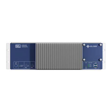
Sel SEL-734W User manual

Date Code 20191014 Information Sheet SEL-734W and SEL-WCS
SEL-734W and SEL-WCS
The SEL-734W Wireless Capacitor Bank Control is a system that includes the
controlling device (SEL-734W) and the line current sensors (8340). The sensors
report line in the current via radio transmission. The SEL-734W includes a radio
receiver used solely for the purpose of receiving the transmissions from the line
current sensors. A capacitor bank control uses measurements of voltage and cur-
rent on the distribution lines of an electric utility to determine if the distribution
of electric power can be made more efficient by connecting a capacitor from the
phase to the neutral conductors of the distribution system. Based on user-select-
able settings, the SEL-734W will drive the capacitor bank switches to connect/
disconnect the capacitors from the power lines of the distribution system. Opera-
tion of the SEL-734W is the same as the operation of the SEL-734B with the
exception of how the line currents are read.
The SEL-734B accepts wires carrying low-level voltages that are an analog rep-
resentation of the current in each of the power system conductors. These wires
are connected to sensors attached to the power lines, with the sensors converting
the current to low-level voltages known as low-energy analog (LEA) signals. For
information that is common to both the SEL-734B and the SEL-734W including
installation, operation, and settings, refer to the documents found at
www.selinc.com/products/734B. For information on how the SEL-734W and the
SEL-734B differ, refer to the sections below.
SEL Wireless Current Sensor (SEL-WCS)
Overview
The SEL-WCS provides measurement of power line current both for the funda-
mental frequency and harmonic frequencies (up to the 15th). This sensor is pro-
vided in a package that is easy to mount using a hot stick and requires no wiring
to the capacitor bank control or to a power source. Power is harvested from the
magnetic field surrounding the power line when current is flowing. The
SEL-WCS operates without the use of a battery, eliminating that maintenance
concern while allowing for a smaller, simpler device. The SEL-WCS measures
the current and updates the SEL-734W periodically, making sure that it has
enough stored energy to complete the measurement and transmit the information
to the SEL-734W before beginning the measurement process. The SEL-734W
provides a measurement range of 2 A to 1000 A. The SEL-WCS is paired to an
SEL-734W by settings selections made on both devices.
Current Measurements
Measurements are made by the sensor and sent to the SEL-734W about once
every 1.1 seconds or as harvested energy allows, whichever is slower. The
SEL-734W will use the last value transmitted in all reporting, calculations, and
actions involving the current until the next update of the current. If the
SEL-734W has not received a recognizable update within a certain timeframe,
the current value is set to zero and stays at zero until the next successful update.
A switch-selectable setting for the SEL-WCS tells the sensor whether it should
calculate the magnitude and phase values of the harmonics. By selecting the
SEL-734W Wireless Capacitor Bank Control
and SEL-WCS Wireless Current Sensor

2
S E L- 7 3 4 W a n d S E L- W C S I n f o r m a t i o n S h e e t D a t e C o d e 2 0 1 9 1 0 1 4
Product Overview
option for no calculation of the harmonics, the sensor will send updates more fre-
quently (for line currents below 200 A). Tabl e 1 compares typical update periods
with and without harmonics calculation for certain values of line current.
Product Overview
SEL-WCS
Figure 1 depicts the key components of the SEL-WCS. Each SEL-WCS mounts
onto and monitors the line current on one phase. The SEL-WCS periodically
sends the load data information including the harmonics to a SEL-734W.
Shotgun Stick Loop and Spring
The shotgun stick loop allows the SEL-WCS to be mounted on the line or
removed from the line using only a shotgun stick. The springs simplify installa-
tion on overhead lines and hold the SEL-WCS in position. See SEL-WCS Instal-
lation for more information.
Current Transformer (CT)
The SEL-WCS split-core CT harvests energy to power the device and accurately
measure load current and harmonics of the current.
Table 1 WCS Typical Update Period Versus Line Current
Line Current
(amps rms)
No-Harmonics Update Period
(seconds)
Harmonics Update Period
(seconds)
220 64
5 4.1 12.5
10 2.0 5.7
20 1.1 2.0
50 1.1 1.4
100 1.1 1.3
Figure 1 SEL-WCS Key Components
Shotgun Stick Loop
Current Transformer
Twistlock Housing
for Setting Access
Omnidirectional Antenna for
the Radio Transmitter
Control (DIP)
Switch Bank
Spring for Secure Installation

3
Date Code 20191014 Information Sheet SEL-734W and SEL-WCS
Product Overview
Integrated Radio
The 900 MHz radio module is mounted inside the SEL-WCS cone for environ-
mental protection. The radio communicates to a single SEL-734W to transmit
load data.
Dip Switches
The control DIP switches inside the housing allow easy selection of the identifi-
cation of each sensor. An SEL-WCS has a set of four DIP switches for a Network
ID, two DIP switches for a phase ID, and a single DIP switch that determines
whether an SEL-WSC sends the harmonic content information to the SEL-734W.
SEL-734W
Figure 2 shows an SEL-734W. The orange rectangle in the figure indicates the
switches where you make the different settings from those on the SEL-734B.
Settings
Settings are made on both the SEL-WCS and the SEL-734W to make the infor-
mation sent by the SEL-WCS available and correct for use in the SEL-734W. The
Network ID setting is common to both devices. To use other settings, refer to the
information provided below on settings specific to each device.
For the SEL-734W to use the information from the SEL-WCS, the value selected
on the SEL-734W must match the value selected on the SEL-WCS. This setting
allows an SEL-734W to operate within the range of many SEL-WCSs, yet be
able to listen to the one(s) that are intended to be used with that SEL-734W.
Figure 2 SEL-734W

4
S E L- 7 3 4 W a n d S E L- W C S I n f o r m a t i o n S h e e t D a t e C o d e 2 0 1 9 1 0 1 4
Product Overview
SEL-WCS Settings
Network ID settings
The SEL-WCS has a 4-bit DIP switch that allows it to configure the Network ID.
Table 2 shows the frequency associated with each Network ID. DIP switches
SW1–SW4 shown in Figure 2 are for the Network ID.
Harmonic Content DIP Switch Setting
DIP switch SW7 configures the SEL-WCS, whether it calculates and sends har-
monic contents of the current to the SEL-734W.
Ta b l e 2
Network ID Frequency (MHz)
0906
1907
2908
3909
4910
5911
6912
7913
8914
9915
10 916
11 923
12 924
13 925
14 926
15 927
Figure 3 DIP Switch Configurations

5
Date Code 20191014 Information Sheet SEL-734W and SEL-WCS
Product Overview
Phase identification Settings
The SEL-WCS uses two DIP switches to configure the phase information.
Table 3 shows the phase identification settings.
SEL-734W Settings
The Network ID must match the Network ID setting for the SEL-WCSs used
with this SEL-734W. The other settings on the 734W are explained below.
Voltage Phases
The Voltage Phases setting is used to allow the SEL-734W to calculate power,
VAs, and VARs for all three phases when the SEL-734W is only sensing a single-
phase voltage. This is done by reusing the magnitude of the measured voltage
phase, but rotating by ±120 degrees to get the two missing voltage phases. SW1
of the system setting DIP switches sets this option. When the switch is moved to
the down position, the SEL-734W only has single-phase data available.
Distance to Sensor
The Distance to Sensor setting is used to ensure that an SEL-734W does not hear
data from an SEL-WCS on the system that has reused the Network ID of the
SEL-WCS associated with this SEL-734W. This happens where there are more
SEL-734Ws in a limited area than the 16 available Network IDs. Although
unlikely, under ideal conditions, an SEL-734W can receive data from an
SEL-WCS that is farther than a mile away. This setting reduces the sensitivity of
the SEL-734W radio receiver so it will not receive data from distant SEL-WCSs.
Line Current Range
The Line Current Range setting refers to the maximum current expected to flow
in the line during normal (non-fault) conditions. It is used to increase the resolu-
tion of the current reported to the SEL-734W. When in the > 200 A range, the
resolution is approximately 0.25 A. For the lower range setting, the resolution is
approximately 0.05 A.
Table 3 Phase Identification Configuration
Switch Settings Phase
00 A
01 B
10 C
11 Reserved
Figure 4 SEL-734W DIP Switch Settings

6
S E L- 7 3 4 W a n d S E L- W C S I n f o r m a t i o n S h e e t D a t e C o d e 2 0 1 9 1 0 1 4
Product Overview
SEL-WCS Installation
Install the SEL-WCS on a distribution line by using an industry-standard shotgun
stick.
Step 1. Use a shotgun stick to grasp the hook eye on the side of the SEL-WCS
and place the device on the line so that the opening hangs over the line.
Step 2. Apply slight downward and sideways pressure until the device is
closed around the line. The spring mechanism should be pushed in so
that it wraps around the line.
Step 3. Apply slight upward pressure until the device is secured around the
line as shown in Figure 7.
Step 4. Use the shotgun stick to adjust the transmitter orientation so that it is
directly vertical. This is important to ensure the best propagation
characteristics for the internal antenna.
SEL-734W Installation
The SEL-734W cabinet is made to mount to a four-jaw meter mount socket.
Refer to the SEL-734B literature on selinc.com for instructions on mounting this unit.
Figure 5
Figure 6
Figure 7

7
Date Code 20191014 Information Sheet SEL-734W and SEL-WCS
Safety Information
Safety Information
Regulatory Information
The SEL-WCS is approved for use only with specific output power configura-
tions that have been tested and approved. Modifications to the SEL-WCS, the
antenna system, and the power output that have not been explicitly specified by
the manufacturer are not permitted and may render the radio noncompliant with
applicable regulatory authorities. The radio equipment described in this manual
emits radio frequency energy. Professional installation is required.
United States (FCC)
Per FCC 15.19(a)(3) and (a)(4) This device complies with part 15 of the FCC
Rules. Operation is subject to the following two conditions: (1) This device may
not cause harmful interference, and (2) this device must accept any interference
received, including interference that may cause undesired operation.
Per FCC 15.21, changes or modifications not expressly approved by the party
responsible for compliance could void the user's authority to operate the equip-
ment.
Canada
DANGER
Install fault transmitters and
sensors in accordance with
normal safe operating
procedures. These instructions
are not intended to replace or
supersede existing safety or
operating requirements. Only
trained qualified personnel with
knowledge of high voltage
safety should install or operate
fault transmitters.
CAUTION
Although the power level is low,
concentrated energy from a
directional antenna may pose a
health hazard. Do not allow
users to come closer than 23 cm
(9 in) to the transmitter when it
is operating.
DANGER
To ensure proper safety and
operation, the equipment
ratings, installation instructions,
and operating instructions must
be checked before
commissioning or maintenance
of the equipment. The integrity
of any protective conductor
connection must be checked
before carrying out any other
actions. It is the responsibility of
the user to ensure that the
equipment is installed,
operated, and used for its
intended function in the manner
specified in this manual. If
misused, any safety protection
provided by the equipment may
be impaired.
This device complies with Industry Canada
license-exempt RSS standard(s). Operation is
subject to the following two conditions: (1)
this device may not cause interference, and
(2) this device must accept any interference,
including interference that may cause unde-
sired operation of the device.
Le présent appareil est conforme aux CNR
d'Industrie Canada applicables aux appareils
radio exempts de licence. L'exploitation est
autorisée aux deux conditions suivantes : (1)
l'appareil ne doit pas produire de brouillage ;
(2) l'utilisateur de l'appareil doit accepter tout
brouillage radioélectrique subi, même si le
brouillage est susceptible d'en compromettre
le fonctionnement.
Per RSS-Gen, Radio apparatus shall comply
with the requirements to include required
notices or statements to the user of equipment
with each unit of equipment model offered for
sale.
Selon RSS-Gen, un appareil radio doit être
conforme avec les exigences d'inclure requis
avis ou déclarations à l'utilisateur de l'équipe-
ment avec chaque unité de modèle d'équipe-
ment offert pour vente.
These statements are required regarding
antennas and for certain types of equipment.
Please see the specified sections of RSS-Gen
for details and suggested verbiage: Transmit-
ter Antenna -Section 6.8
Ces déclarations sont obligatoires concernant
antennes et pour certains types d'équipement.
Veuillez consulter les sections spécifiées de
RSS-Gen pour plus de détails et le verbiage
suggéré: Emetteur Antenne - Section 6.8
Devices operating in the 5250 - 5350 MHz
band shall be labeled "for indoor use only".
Alternatively, that text can be included in the
user manual and not on the device. Note how-
ever the user manual is the only option avail-
able for devices operating in the 5150 - 5250
MHz band. In all cases the user manual shall
contain instructions "for indoor use only".
Périphériques fonctionnant dans la bande
5250 - 5350 MHz la bande doit porter la men-
tion "pour utilisation à l'intérieur unique-
ment". Alternativement, ce texte peut être
inclus dans le manuel de l'utilisateur et non
sur l'appareil. Notez cependant le manuel
d'utilisation est la seule option disponible
pour les appareils fonctionnant dans le 5150 –
5250 Bande MHz. Dans tous les cas, le man-
uel d'utilisation doit contient des instructions
"pour une utilisation en intérieur uniquement".

8
S E L- 7 3 4 W a n d S E L- W C S I n f o r m a t i o n S h e e t D a t e C o d e 2 0 1 9 1 0 1 4
Safety Information
Dangers, Warnings, and Cautions
This manual uses three kinds of hazard statements, defined as follows:
Safety Symbols
The following symbols apply to this device.
Safety Marks
The following statements apply to this device.
DANGER
Indicates an imminently hazardous situation that, if
not avoided, will result in death or serious injury.
WARNING
Indicates a potentially hazardous situation that, if
not avoided, could result in death or serious injury.
CAUTION
Indicates a potentially hazardous situation that, if
not avoided, may result in minor or moderate injury
or equipment damage.
CAUTION
Refer to accompanying documents.
ATTENTION
Se reporter à la documentation.
Protective earth (ground) Terre de protection
Direct current Courant continu
Instruction manual Manuel d’instructions
DANGER
Disconnect or de-energize all external connections before opening this
device. Contact with hazardous voltages and currents inside this
device can cause electrical shock resulting in injury or death.
DANGER
Débrancher tous les raccordements externes avant d’ouvrir cet appa-
reil. Tout contact avec des tensions ou courants internes à l’appareil
peut causer un choc électrique pouvant entraîner des blessures ou la
mort.
DANGER
Contact with instrument terminals can cause electrical shock that can
result in injury or death.
DANGER
Tout contact avec les bornes de l’appareil peut causer un choc élec-
trique pouvant entraîner des blessures ou la mort.
WARNING
Use of this equipment in a manner other than specified in this manual
can impair operator safety safeguards provided by this equipment.
AVERTISSEMENT
L’utilisation de cet appareil suivant des procédures différentes de
celles indiquées dans ce manuel peut désarmer les dispositifs de pro-
tection d’opérateur normalement actifs sur cet équipement.
WARNING
Have only qualified personnel service this equipment. If you are not
qualified to service this equipment, you can injure yourself or others,
or cause equipment damage.
AVERTISSEMENT
Seules des personnes qualifiées peuvent travailler sur cet appareil. Si
vous n’êtes pas qualifiés pour ce travail, vous pourriez vous blesser
avec d’autres personnes ou endommager l’équipement.

9
Date Code 20191014 Information Sheet SEL-734W and SEL-WCS
Safety Information
WARNING
Do not perform any procedures or adjustments that this instruction
manual does not describe.
AVERTISSEMENT
Ne pas appliquer une procédure ou un ajustement qui n’est pas décrit
explicitement dans ce manuel d’instruction.
CAUTION
Equipment components are sensitive to electrostatic discharge (ESD).
Undetectable permanent damage can result if you do not use proper
ESD procedures. Ground yourself, your work surface, and this equip-
ment before removing any cover from this equipment. If your facility is
not equipped to work with these components, contact SEL about
returning this device and related SEL equipment for service.
ATTENTION
Les composants de cet équipement sont sensibles aux décharges élec-
trostatiques (DES). Des dommages permanents non-décelables
peuvent résulter de l’absence de précautions contre les DES. Raccor-
dez-vous correctement à la terre, ainsi que la surface de travail et
l’appareil avant d’en retirer un panneau. Si vous n’êtes pas équipés
pour travailler avec ce type de composants, contacter SEL afin de
retourner l’appareil pour un service en usine.

4
S E L- 7 3 4 W a n d S E L-W C S I n f o r m a t i o n S h e e t D a t e C o d e 2 0 1 9 1 0 1 4
SEL-WCS Specifications
Compliance
Designed and manufactured under an ISO 9001 certified quality
management system
General
Operating Temperature
–40° to +85°C (–40° to +185°F)
Storage Temperature
–40° to +85°C (–40° to +185°F)
Operating Environment
Pollution Degree: 2
Relative Humidity: 5%–95%, noncondensing
Maximum Altitude: 2000 m
Ingress Protection
IP67
Clamp Range (SEL WCS)
6.35 mm to 31.75 mm (0.25 in to 1.25 in)
Dimensions
141.7 mm diameter x 177.0 mm height
(5.58 in. diameter x 6.97 in. height)
Weight
Wireless Current Sensor: 0.85 kg (1.9 lb)
Overvoltage
Category III
Insulation Class
Class III
System
Power System Frequency Range
45–65 Hz
Load Magnitude Accuracy
1% (preliminary)
Phase Measurement Accuracy
~3 degrees
Maximum Voltage
38 kV (L-L)
Maximum Steady-State Load Current
1000 A (Thermal Rating preliminary)
Maximum Fault Current
25 kA for 10 cycles
Power
Minimum Load Current
2A
Radio System
Frequency Band
902–928 MHz ISM band (U.S.A, Canada)
SEL WCS
TX Power (Effective Isotropic Radiated Power)
50 mW (17 dBm) peak,
40 mW (16 dBm) typical
SEL-WCS Receiver Card
Antenna Connector: SMA, 50
RX Sensitivity (1% Error
Rate): TBD
Modulation
FSK
Link Range
TBD
Type Tests
Electromagnetic Compatibility Emissions
Radiated: 47 CFR Part 15.109
Class A
Conducted: 47 CFR Part 15.107
Class A
Electromagnetic Compatibility Immunity
Electrostatic Discharge: IEC 61000-4-2:2008
IEEE C37.90.3-2001
Discharges:
Indirect: ±8 kV
Contact: ±8 kV
Air: ±15 kV
Radiated: IEEE C37.90.2-2004
20 V/mrms; 80 MHz to 1 GHz
>35 V/mrms with 80% 1 kHz sine wave
modulation
Surge: IEC 61000-4-5:2005
PT: ±0.5; 1.0; 2.0 kV; line-to-line
PT: ±0.5; 1.0, 2.0, 4.0 kV; line-to-earth
Conducted: IEC 61000-4-6:2008
10 Vrms; 150 kHz to 80 MHz
80% 1 kHz sine wave modulation
Power Frequency Magnetic
Field:
IEC 61000-4-8:2009
100 A/m; 50/60 Hz; 60 s
1000 A/m; 50/60 Hz; 1–3 s
IEEE Surge Withstand
Capability:
IEEE C37.90.1-2012
Damped Oscillatory (1 MHz)—
(CM & DM)
Power Input: ±2.5 kV
Communications Ports: ±2.5 kV
(CM only)
Fast Transient (5 kHz)—(CM & DM)
Power Input: ±4.0 kV
Communications Ports: ±4.0 kV
(CM only)
Environmental
Cold: IEC 60068-2-1:2007
Cold Profile Ad; –40°C; 16 hours;
operational
Dry Heat: IEC 60068-2-2:2007
Dry Heat Profile Bd; +85°C; 16 hours;
operational
Damp Heat; Cyclic: IEC 60068-2-30:2005
Damp Heat Profile Db; +25° to +55°C;
relative humidity 93%; 6 cycles
Vibration: IEC 60255-21-1:1988
Class 1 Vibration Endurance
Class 2 Vibration Response
Shock and Bump: IEC 60255-21-2:1988
Class 1 Shock Withstand
Class 1 Bump
Class 2 Shock Response
Seismic: IEC 60255-21-3:1993
Class 2 Quake Response

5
Date Code 20191014 Information Sheet SEL-734W and SEL-WCS
SEL-WCS Specifications
Table 2 Certifications by Country
Country Part
Number Authority Reference
U.S.A. and
Colombia
TBD FCC TBD
Canada TBD IC TBD
This manual suits for next models
1
Table of contents
Other Sel Controllers manuals