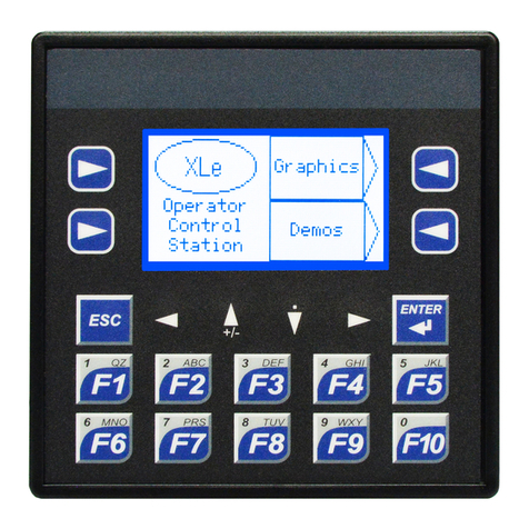
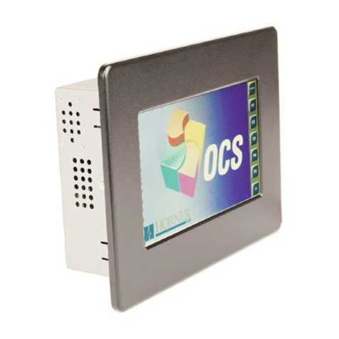
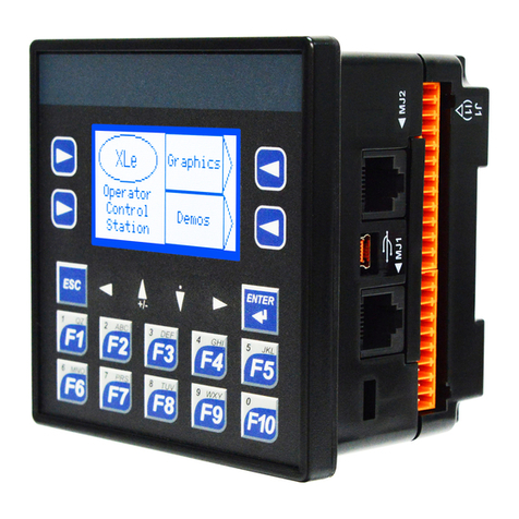
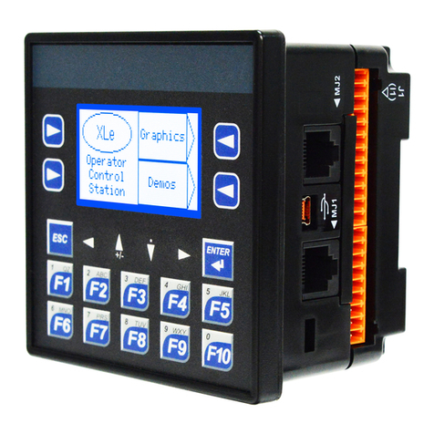
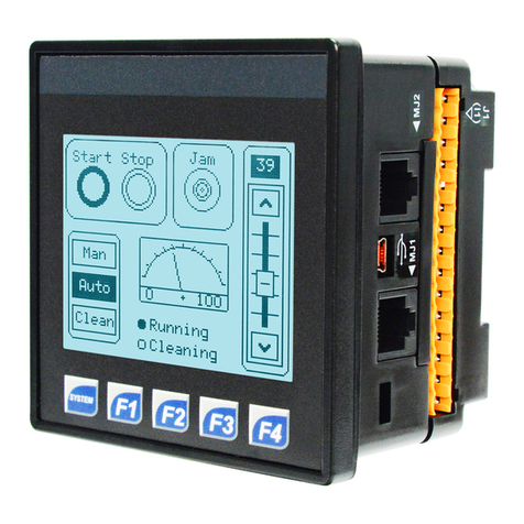
HORNER HE-XPC1E2 User manual

Page 1
XL4 Prime - Model 2
12 DC In, 6 Relay Out, 4 – 12-bit Analog In
MAN1320-21-EN_XL4P_Mod2
Part Numbers
GlobalPartNumber HE-XPC1E2
EuropeanPartNumber HEXP251C112
User Manual and Add-Ons
FindthedocumentsviatheDocumentationSearch.
Part # Description
MAN0964 XL4&XL4PrimeUserManual
HE-BAT013 CR2032LithiumBattery
HE-XCK ProgrammingCables
HE-XDAC 2channelAnalogOutputI/Ooptionkit,
selectable0-10V,+/-10V,4-20mA.
HE-XDAC107 4channelAnalogOutputI/Ooptionkit,
selectable0-10V,+/-10V,4-20mA.
HE-XKIT BlankI/OBoard
HE200MJ2TRM Adapter,RJ45(8P8C)maleto8-pos-
itionterminalstrip.
HE-FBD001 Ferritecoreforfilteringoutelectrical
noise.
Backup Battery
TheXL4PrimeusesaRenataCR2032lithiumbatteryto
runtheRealTimeClock.Thebatterylifeis7-10years.
Table of Contents
PartNumbers 1
UserManualandAdd-Ons 1
BackupBattery 1
TECHNICAL SPECIFICATIONS 2
GeneralSpecifications 2
ControlandLogic 2
UserInterface 2
Connectivity 2
USBWebcams 2
CONTROLLER OVERVIEW 3
OverviewofOCS 3
PowerWiring 3
MODEL 2 SPECIFICATIONS 4
DigitalDCInput 4
DigitalRelayOutputs 4
AnalogInputs,MediumResolution 4
WIRING: INPUTS AND OUTPUTS 5
AnalogInputsInformation 5
DigitalInputs 5
RelayLife 5
JumperSettingsforModel2 5
BackPanelTorqueRatings 5
J1Wiring-DigitalIn/AnalogIn 6
J2Wiring-RelayOut/AnalogorDigitalIn 6
WiringDetails 6
BUILT-INI/O 6
AnalogInputTranzorbFailure 6
COMMUNICATIONS 7
SerialCommunication 7
DipSwitches 7
CANCommunications 7
Ethernet 7
DIMENSIONS & INSTALLATION 8
XL4&XL4PrimeDimensions 8
InstallationInformation 8
InstallationProcedure 8
SAFETY & MAINTENANCE 9
Warnings 9
FCCCompliance 9
TechnicalSupport 9
Precautions 9

Page 2
TECHNICAL SPECIFICATIONS
General Specifications
TypicalPowerBack-
light100%
407mA@10V(4.07W)
192mA@24V(4.61W)
PowerBacklight@
50% 167mA@24V(4.01W)
PowerBacklightOFF 165mA@24V(3.96W)
RequiredPower
(Inrush)
2Afor<1ms@24VDC,
DCswitched
HeaterOption* 250mAwithheater*(24VDC)
PrimaryPowerRange 10-30VDC
10-24VDC(withheater*)
Max.Current 500mA,Class2
750mA,Class2(withheater*)
RelativeHumidity 5to95%,Non-Condensing
ClockAccuracy
+/-20ppmmaximumat25°C
(+/-1min/month)
RealTimeClock BatteryBacked,Rechargeable
Lithium
Operating
Temperature
-10°Cto+60°C
-40°Cto+60°C(withheater*)
Storage
Temperature -20°Cto+60°C
Weight 12oz/340g(withoutI/O)
Altitude Upto2000m
PollutionDegree Degree2Rating
Certifications(UL/CE) NorthAmericaorEurope
EnclosureType 1,3R,4,4X,12,12K&13
*HeaterOption(Model#plus"-22")
Control and Logic
ControlLang.
Support
Register-BasedAdvanced
LadderLogic;
Variable-BasedAdvanced
Ladder;
IEC61131-3Languages
LogicProgramSize 2MB,maximum
ScanRate .02ms/kB
DigitalInputs 2048
DigitalOutputs 2048
AnalogInputs 512
AnalogOutputs 512
Gen.Purpose
Registers
50,000(words)Retentive
16,384(bits)Retentive
16,384(bits)Non-retentive
User Interface
DisplayType 3.5”TFTColor
ScreenBrightness 640cd/m2(nits)
Resolution QVGA(320x240)
Color 16-bit(65,535)
User-Program.
Screens
1023maxpages;1023objects
perpage
Backlight LED-50,000hourlife
BrightnessControl 0-100%viaSystemRegister
%SR57
NumberofKeys 5
Connectivity
SerialPorts 1RS-232and1RS-485on
singularModularJack
USBmini-B USB2.0(480MHz)Programming
&DataAccess
USBA(500mAmax) USB2.0(480MHz)forUSBflash
drives(2TB)
CANPort
Isolated1kV
RemoteI/O,Peer-to-peer
Comms,Cscape
CANProtocols CsCAN,CANopen,DeviceNet,
J1939
Ethernet 10/100Mb(Auto-MDX)
EthernetProtocols TCP/IP,ModbusTCP,FTP,
SMTP,EGD,ICMP,ASCII
RemoteI/O SmartRail,SmartStix,
SmartBlock,SmartMod
RemovableMemory
microSD,SDHC,SDXCIN
FAT32format,supportfor32GB
max.ApplicationUpdates,
Datalogging
USB Webcams
USBWebcamssupportedshouldsupporttheUVC(USB
Videoclass)protocolfortheOCStobeabletodisplay
video.MostUSBbasedvideodevicessupportthistoday.
Specialfeaturesuchaszoomandhighdefinitionarenot
supportedbytheOCS.

Page 3
CONTROLLER OVERVIEW
Overview of OCS
1. Touchscreen
2. HighCapacitymicroSDSlot
3. RS232/RS485SerialPort
4. CANPort(viaRJ485)
5. LANPort
6. USBMini-BPort
7. AnalogI/O
8. DCInputs
9. DCOutputs
10. DCPower
NOTE:See"Precautions"onpage9aboutUSBand
grounding.
Power Wiring
NOTE:ThePrimaryPowerRangeis10VDCto30VDC.
Primary Power Port Pins
PIN Signal Description
1Ground FrameGround
2DC- InputPowerSupplyGround
3DC+ InputPowerSupplyVoltage
DC Input / Frame
lSolid/StrandedWire:12-24awg(2.5-0.2mm)
lStriplength:0.28”(7mm)
lTorque,TerminalHold-DownScrews:4.5–7in-lbs
(0.50–0.78N-m)
lDC-isinternallyconnectedtoI/OV-,butisisolated
fromCANV-.AClass2powersupplymustbeused.
Power Up
1. Optional:Attachferritecorewithaminimumoftwo
turnsoftheDC+andDC-signalsfromtheDCsupply
thatispoweringthecontrollers.Seepage1.
2. Connecttoearthground.
3. Applyrecommendedpower.

Wiring:Model 2
Page 4
MODEL 2 SPECIFICATIONS
Digital DC Input
InputsperModule 12including4configurableHSC
inputs
CommonsperModule 1
InputVoltageRange 12VDC/24VDC
AbsoluteMax.
Voltage 30VDCMax.
InputImpedance 10kΩ
InputCurrent PositiveLogic NegativeLogic
UpperThreshold
LowerThreshold
0.8mA
0.3mA
-1.6mA
-2.1mA
Max.UpperThreshold 8VDC
Min.LowerThreshold 3VDC
OFFtoONResponse 1ms
ONtoOFFResponse 1ms
HighSpeedCounter
MaxFreq* 1MHz
Digital Relay Outputs
OutputsperModule 6Relay
CommonsperModule 6
Max.OutputCurrent
perRelay 3A@250VAC,resistive
Max.TotalOutput
Current 5Acontinuous
Max.OutputVoltage 275VAC,30VDC
Max.SwitchedPower 1000VAC,150W
ContactIsolationto
Ground 1000VAC
Max.VoltageDropat
RelatedCurrent 0.5V
ExpectedLife(see
belowderatingchart
fordetails)
NoLoad:5,000,000
RatedLoad:100,000
Max.SwitchingRate 300CPMatnoload20CPMat
ratedload
Type MechanicalContact
ResponseTime
Oneupdateperladderscan
plus10ms
Analog Inputs, Medium Resolution
NumberofChannels 4
InputRanges 0-10VDC,0-20mA,4-20mA
SafeInputVoltage
Range -0.5Vto12V
InputImpedance
(clamped@-0.5VDC
to12VDC)
Current Mode:100Ω
Voltage Mode:500kΩ
NominalResolution 12Bits
%AIFullScale 0V,20mA,100mV:
32,000countsfullscale
Max.OverCurrent 35mA
ConversionSpeed OnceperLadderScan
MaxErrorat25˚C
(excludingZero)
AdjustingFiltering
maytighten
4–20mA1.00%
0-20mA1.00%
0-10VDC1.50%
Filtering
160HzHash(noise)Filter,1-128
ScanDigitalRunningAverageFil-
ter

Wiring:Model 2
Page 5
WIRING: INPUTS AND OUTPUTS
Analog Inputs Information
Rawinputvaluesforchannels1-4arefoundintheregisters
asInteger-typedatawitharangefrom0–32000.
AnaloginputsmaybefiltereddigitallywiththeFilterCon-
stantfoundintheCscapeHardwareConfigurationforAna-
logInputs.Validfiltervaluesare0-7andactaccordingto
thefollowingchart:
Data Values
InputMode: DataFormat,12-bitINT:
0-20mA,4-20mA 0-32000
0-10V 0-32000
Digital Inputs
DigitalinputsmaybewiredineitheraPositiveLogicorNeg-
ativeLogicfashionasshown.ThesettingintheCscape
HardwareConfigurationfortheDigitalInputsmustmatch
thewiringusedinorderforthecorrectinputstatestobe
registered.NojumpersettingsarerequiredforXLEe/XLTe.
Whenusedasanormalinputandnotforhighspeedfunc-
tions,thestateoftheinputisreflectedinregisters%I1–
%I12.
Relay Life
WARNING:Exposuretosomechemicalsmaydegradethe
sealingproper-tiesofmaterialsusedintheTycorelayPCJ.
Cover/Case & Base:MistubishiengineeringPlasticsCorp.
5010GN6-30or5010GN6-30M8(PBT)
Sealing Material:Kishimoto4616-50K(Ipartepoxyresin)
Jumper Settings for Model 2
LocationofI/Ojumpers(JP1&JP2)andwiringconnectors
(J1&J2)withbackcoverremoved.
NOTE:TheCscapeModuleConfigurationmustmatchthe
selectedI/O(JP)jumpersettings.
NOTE:WhenusingJP2(A1-A4),eachchannelcanbeinde-
pendentlyconfigured.
Back Panel Torque Ratings
XLE/XLT:3.0-4.0in-lbs(0.34-0.45N-m)
XL4/XL4 Prime:3.0-4.0in-lbs(0.34-0.45N-m)
EXL6/XL6 Prime:3.0-4.0in-lbs(0.34-0.45N-m)
EXLW/ XLW Prime:3.0-3.5in-lbs(0.34-0.40N-m)
XL7/XL7 Prime:3.0-3.5in-lbs(0.34-0.40N-m)
EXL10/XL10 Prime:3.0-3.5in-lbs(0.34-0.40N-m)

Wiring:Model 2
Page 6
J1 Wiring - Digital In / Analog In
NOTE:The0Vterminalsareinternallyconnected.
J2 Wiring - Relay Out / Analog or
Digital In
Wiring Details
Solid/Stranded Wire:12-24awg(2.5-0.2mm2).
Strip Length:0.28”(7mm).
Torque, Terminal Hold-Down Screws:4.5–7in-lbs
(0.50–0.78N-m).
BUILT-IN I/O
TheI/OismappedintoOCSRegisterspace,inthreesep-
arateareas–Digital/AnalogI/O,High-SpeedCounterI/O,
andHigh-speedOutputI/O.Digital/AnalogI/Olocationis
fixedstartingat1,butthehigh-speedcounterandhigh-
speedoutputreferencesmaybemappedtoanyopen
registerlocation.
Digital and Analog I/O Functions
DigitalInputs %I1-12
Reserved %I13-32
ESCPAlarm n/a
DigitalOutputs %Q1-6
Reserved %Q7-24
AnalogInputs %AI1-4
Reserved %AI5-12
AnalogOutputs n/a
Reserved n/a
Analog Input Tranzorb Failure
AcommoncauseofAnalogInputTranzorbFailureonAna-
logInputsModel2,3,4&5:Ifa4-20mAcircuitisinitially
wiredwithlooppower,butwithoutaload,theanaloginput
couldsee24VDC.Thisishigherthantheratingofthetran-
zorb.ThiscanbesolvedbyNOTconnectinglooppower
priortoloadconnection,orbyinstallingalow-costPTCin
seriesbetweentheloadandanaloginput.

Page 7
COMMUNICATIONS
Serial Communication
MJ1/2 Serial Ports
2SerialPortson1ModuleJack(8posn)
MJ1:RS-232w/FullHandshaking
MJ2:RS-485Half-Duplex
MJ1 PINS MJ2 PINS
PIN SIGNAL DIRECTION SIGNAL DIRECTION
8TXD OUT -- --
7RXD IN -- --
60V GROUND 0V GROUND
5+5V@
60mA OUT +5V@
60mA OUT
4RTS OUT -- --
3CTS IN -- --
2-- -- RX-/TX- IN/OUT
1-- -- RX+/
TX+ IN/OUT
NOTE:AttachoptionalFerriteCore(HE-FBD001)witha
minimumoftwoturnsofserialcable.
Dip Switches
DIP Switches
PIN NAME FUNCTION DEFAULT
1RS-485
Termination
ON=
Terminated OFF
2Spare AlwaysOFF OFF
3FactoryUse AlwaysOFF OFF
TheDIPswitchesareusedtoprovideabuilt-intermination
totheMJ2portifneeded.Theterminationfortheseports
shouldonlybeusedifthisdeviceislocatedateitherendof
themultidrop/daisy-chainedRS-485network.
CAN Communications
CAN Pin Assignments
PIN SIGNAL DESCRIPTION
1V- CANGround–Black
2CN_L CANDataLow–Blue
3SHLD ShieldGround–None
4CN_H CANDataHigh–White
5V+(NC) NoConnect–Red
lSolid/Stranded Wire:12-24awg(2.5-0.2mm).
lStrip Length:0.28”(7mm).
lLockingspring-clamp,two-terminatorspercon-
ductor.
lTorque, Terminal Hold-Down Screws:4.5–7in-
lbs(0.50–0.78N-m).
lV+pinisnotinternallyconnected,theSHLDpinis
connectedtoEarthgroundviaa1MΩresistorand10
nFcapacitor.
Ethernet
Green LED indicates link-whenillu-
minated,datacommunicationisavailable.
Yellow LED indicates activity-when
flashing,dataisintransmission.

Page 8
DIMENSIONS & INSTALLATION
XL4 & XL4 Prime Dimensions
*+/-0.1mmcutouttolerance
Installation Information
lTheXL4/XL4Primeutilizesaclipinstallationmethod
toensurearobustandwatertightsealtotheenclos-
ure.Pleasefollowthestepsbelowfortheproper
installationandoperationoftheunit.
lThisequipmentissuitableforClassI,Division2,
GroupsA,B,CandDornon-hazardouslocations
only.
lDigitaloutputsshallbesuppliedfromthesame
sourceastheoperatorcontrolstation.
lJumpersonconnectorJP1shallnotberemovedor
replacedwhilethecircuitisliveunlesstheareais
knowntobefreeofignitableconcentrationsofflam-
mablegasesorvapors.
lWARNING-TheUSBportsareforoperationalmain-
tenanceonly.Donotleavepermanentlyconnected
unlessareaisknowntobenon-hazardous.
Installation Procedure
1. Carefullylocateanappropriateplacetomountthe
OCSBesuretoleaveenoughroomatthetopofthe
unitforinsertionandremovalofthemicroSD™card.
2. Carefullycutthehostpanelperthediagram,cre-
atinga92mmx92mm+/-0.1mmopeningintowhich
theOCSmaybeinstalled.Iftheopeningistoolarge,
watermayleakintotheenclosure,potentiallydam-
agingtheunit.Iftheopeningistoosmall,theOCS
maynotfitthroughtheholewithoutdamage.
3. Removeanyburrsandorsharpedgesandensure
thepanelisnotwarpedinthecuttingprocess.
4. RemoveallRemovableTerminalsfromtheOCS.
InserttheOCSthroughthepanelcutout(fromthe
front).Thegasketmustbebetweenthehostpanel
andtheOCS.
5. Installandtightenthefourmountingclips(provided
inthebox)untilthegasketformsatightseal.NOTE:
Maxtorqueis0.8to1.13Nm,7to10in-lbs.
6. ReinstalltheI/ORemovableTerminalBlocks.Con-
nectcommunicationscablestotheserialport,USB
ports,Ethernetport,andCANportasrequired.

Page 9
SAFETY & MAINTENANCE
Warnings
1. Toavoidtheriskofelectricshockorburns,alwayscon-
nectthesafety(orearth)groundbeforemakinganyother
connections.
2. Toreducetheriskoffire,electricalshock,orphysical
injury,itisstronglyrecommendedtofusethevoltage
measurementinputs.Besuretolocatefusesascloseto
thesourceaspossible.
3. Replacefusewiththesametypeandratingtoprovidepro-
tectionagainstriskoffireandshockhazards.
4. Intheeventofrepeatedfailure,doNOTreplacethefuse
againasrepeatedfailureindicatesadefectivecondition
thatwillNOTclearbyreplacingthefuse.
5. Onlyqualifiedelectricalpersonnelfamiliarwiththecon-
structionandoperationofthisequipmentandthehazards
involvedshouldinstall,adjust,operate,orservicethis
equipment.
6. Readandunderstandthismanualandotherapplicable
manualsintheirentiretybeforeproceeding.Failureto
observethisprecautioncouldresultinseverebodilyinjury
orlossoflife.
7. WARNING-Batterymayexplodeifmistreated.Donot
recharge,disassemble,ordisposeofinfire.
8. WARNING - EXPLOSION HAZARD-Batteriesmustonly
bechangedinanareaknowntobenon-hazardous.
9. WARNING-Donotdisconnectwhilecircuitisliveunless
areisknowtobenon-hazardous.
FCC Compliance
ThisdevicecomplieswithPart15oftheFCCRules.Operationis
subjecttothefollowing
twoconditions:
1. Thisdevicemaynotcauseharmfulinterference.
2. Thisdevicemustacceptanyinterferencereceived,includ-
inginterferencethatmaycauseundesiredoperation.
Technical Support
North America
1(317)916-4274
(877)665-5666
www.hornerautomation.com
Europe
+353(21)4321-266
www.hornerautomation.eu
Precautions
Allapplicablecodesandstandardsneedtobefollowedinthe
installationofthisproduct.Adheretothefollowingsafetypre-
cautionswheneveranytypeofconnectionismadetothemodule:
1. Connectthesafety(earth)groundonthepowerconnector
firstbeforemakingany
2. otherconnections.
3. Whenconnectingtotheelectriccircuitsorpulse-initiating
equipment,opentheir
4. relatedbreakers.
5. DoNOTmakeconnectiontolivepowerlines.
6. Makeconnectionstothemodulefirst;thenconnecttothe
circuittobemonitored.
7. Routepowerwiresinasafemannerinaccordancewith
goodpracticeandlocalcodes.
8. Wearproperpersonalprotectiveequipmentincluding
safetyglassesandinsulatedgloveswhenmakingcon-
nectionstopowercircuits.
9. Ensurehands,shoes,andflooraredrybeforemakingany
connectiontoapowerline.
10. MakesuretheunitisturnedOFFbeforemakingcon-
nectiontoterminals.
11. Makesureallcircuitsarede-energizedbeforemakingcon-
nections.
12. Beforeeachuse,inspectallcablesforbreaksorcracksin
theinsulation.Replace
13. immediatelyifdefective.
14. UsecopperconductorsinFieldWiringonly,60/75˚C.
15. UsecautionwhenconnectingcontrollerstoPCsviaserial
orUSB.PCs,especiallylaptops,mayuse“floatingpower
supplies”thatareungrounded.Thiscouldcauseadam-
agingvoltagepotentialbetweenthelaptopandcontroller.
Ensurethecontrollerandlaptoparegroundedformax-
imumprotection.ConsiderusingaUSBisolatordueto
voltagepotentialdifferencesasapreventativemeasure.

This manual suits for next models
2
Table of contents
Other HORNER Controllers manuals

HORNER
HORNER XLE-Model 2 User manual

HORNER
HORNER XLW PRIME User manual

HORNER
HORNER HE-EXL1E0 User manual

HORNER
HORNER HE-XPC1E3 User manual

HORNER
HORNER EXL6 3 User manual

HORNER
HORNER XL4 User manual

HORNER
HORNER ZX Series User manual

HORNER
HORNER XL6 Series User manual

HORNER
HORNER XL6 Prime Instruction Manual

HORNER
HORNER X7 OCS User manual
Popular Controllers manuals by other brands

Firefly
Firefly FF-211 Important Instructions and Specifications

iLumin
iLumin TSC-30 installation guide

AAON
AAON VCCX-IP Technical guide

Toshiba
Toshiba TMP87CM24AF Hardware user manual

Eliwell
Eliwell Televis EWCM 809/NH3/S manual

Emerson
Emerson Bettis GVO LP DA Installation, operation and maintenance manual