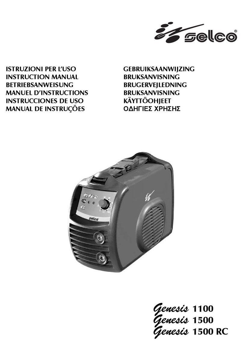
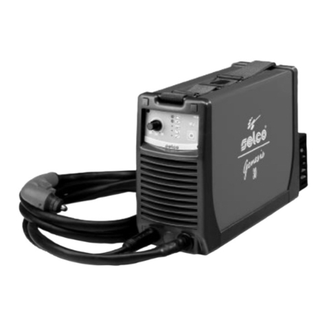
Sel GENESIS 145 Operating instructions

REPAIRS MANUAL
E
N
G
L
I
S
H
Genesis 145

2
SELCO s.r.l
Service Department
c/o SELCO 2
Via Macello, 61
I - 35010 CITTADELLA (Padova) Italy
Tel. +39 049 9413111
Fax. +39 049 9413311
email: [email protected]
Cod. 92.08.018
Edition: 1.0
Revision: 28/03/07
SELCO S.R.L.
Via Palladio, 19
I - 35019 ONARA DI TOMBOLO (PD)
TEL. +39 049 9413111
FAX. +39 049 9413311
email: [email protected]
How to contact Selco Service Department.:
All translation, reproduction and adaptation rights, total or partial
and by any means (including photostat copies, films and microfil-
ms), are reserved and forbidden without the written authorisation of
Selco S.r.l.
INDEX:
1) PURSPOSE OF THE MANUAL........................................................................................................PAG. 3
2) WARNINGS, PRECAUTIONS AND GENERAL NOTICES FOR PERFORMING REPAIRS.................PAG. 4
3) INSTRUMENTS AND CONVENTIONS FOR PERFORMING DIAGNOSIS AND REPAIR................PAG. 5
4) USE AND ROUTINE MAINTENANCE OF POWER SOURCES AND ACCESSORIES
AND TECHNICAL DATES................................................................................................................PAG. 7
5) MACHINE DESCRIPTION..............................................................................................................PAG. 9
6) DESCRIPTION OF GENERATOR FUNCTIONING (BLOCK DIAGRAM).........................................PAG. 12
7) WIRING AND CONNECTIN DIAGRAM.........................................................................................PAG. 17
8) DESCRIPTION OF DIAGNOSTIC INDICATIONS..........................................................................PAG. 20
9) DESCRIPTION, TESTING AND REPLACEMENT OF THE ELECTRONIC BOARDS, CURRENT
CALIBRATION................................................................................................................................PAG. 21
10) TROUBLESHOOTING................................................................................................................. PAG. 33
11) SPARE PARTS LIST....................................................................................................................... PAG. 40
12) NOMINAL DATA..........................................................................................................................PAG. 42

3
1) PURSPOSE OF THE MANUAL
This manual is designed to provide authorised service centres with
the basic information necessary for performing repairs on the mo-
dels Genesis 145.
In order to avoid serious injury to persons or damage to things, this
manual must be used only by qualified technicians.
Selco S.r.l. accepts no liability for any injury to persons or damage
to things that may occur during performance of repairs, even after
reading or practical application of this manual.
For a detailed description of the operation, use and ordinary main-
tenance of the machine, please refer to the “Instructions for use and
maintenance manual” which must always accompany the machine.
The purchaser must follow the directions contained in the above
manual. Failure to do so will exempt Selco from all liability.
The operations described in this manual require the use of a digital
multimeter, an DC ammeter clamp and a basic knowledge of how
the machine works. Basic electrotechnical knowledge is also requi-
red.
Repair consists in identification of the faulty part, included in
the list of available spare parts, and replacement of it.
In the event of failure of an electronic board, repair
entails replacement of the board and not replace-
ment of the faulty electronic component on the
board.
Do not carry out modifications or maintenance not scheduled in
this manual.
If the problem cannot be solved by following the instructions provi-
ded in this manual, contact the Selco Service Department or send
the machine to Selco for repair.

4
2) WARNINGS, PRECAUTIONS AND
GENERAL NOTICES FOR PERFORMING REPAIRS
Repairs must be performed by qualified personnel only.
Before performing the repair, you should read and assimilate the
contents of this manual, in particular the safety precautions.
Avoid performing repairs without the presence of another person
able to provide help in the event of an accident.
The repair of a machine requires access to its internal parts and con-
sequently removal of some of the protective panels. Additional pre-
cautions are therefore necessary with respect to use of the machine
for welding in order to prevent possible injury or damage caused by
contact with
- live parts
- moving parts
- parts at high temperature
CAUTION
LIVE PARTS
When handling internal parts of the machine, remember that ope-
ning of the switch does not prevent the risk of electric shocks: the
machine must be unplugged from the power supply.
Wait approx. one minute before carrying out work on the internal
parts as the capacitors may be loaded at high voltage.
CAUTION
LIVE PARTS OF THE TOOLS
When taking measurements, remember that the measuring instru-
ments can be live and you should therefore avoid touching their
metal parts
CAUTION
MOVING PARTS
Keep your hands well away from the fan when the machine is con-
nected to the power supply. Ensure that the machine is unplugged
and that the fan is at a standstill before replacing it.
CAUTION
PARTS AT HIGH TEMPERATURE
When handling internal parts of the machine, remember that some of
them may be very hot. In particular avoid contact with heat sinks.

5
3) INSTRUMENTS AND CONVENTIONS FOR PER-
FORMING DIAGNOSIS AND REPAIR
3.1) INSTRUMENTS FOR BASIC DIAGNOSIS
The following are required:
- a multimeter with the following scales:
Ohm: from 0 ohm to a few Mohm
Diode testing
Direct voltage (Vdc): from mVdc to 1000 Vdc
Alternating voltage (Vac): from 10 Vac to 700Vac
NOTE: You are advised to use an instrument with automatic scale
since it is not theoretically possible to predict the electrical
quantity to be measured when the machine has broken
down.
- an DC ammeter clamp at least in class 2.5 with e.o.s. 200A
pk.
- alternatively to the ammeter clamp, a shunt can be used with
value 60 mV @ 150 A.
NOTES:
* Remember that other types of shunts can also be used, but accu-
racy is reduced with higher capacities, whereas with lower capa-
cities the measurement must be taken quickly to avoid overhea-
ting of the shunt
* Once fitted, the shunt is at welding potential
* The ammeter clamp is preferable as it is more practical
3.2) REPAIR TOOLS
- Complete set of fork spanners
- Complete set of pipe spanners for hexagonal nuts
- Complete set of blade screwdrivers
- Complete set of Phillips screwdrivers
- Complete set of Allen keys
- Crimper for insulated wire terminals (blue, red and yellow)
- Pliers for AMP contacts
- Tweezers and cutting nippers - type commonly used for
electronic components
- Tongs (dimensions suitable for closing gas pipe clamps)
- Welder for electronic components, minimum power 50 W
- Portable electric drill
3.3) CONVENTIONS
By convention, when a measurement has to be taken between two
points, for example a b, the arrow point indicates where to
apply the red tip of the multimeter (a),while the black tip is applied
at the other end (b).
When a double arrow appears between two measuring points (e.g.:
c d), the voltage to be measured is alternating (normally at
50 Hz), therefore it does not matter in which order the multimeter
terminals are applied.
In drawings and tables, when a voltage measurement appears refer-
ring to terminals of components such as DIODES, BJT, MOSFET and
IGBT, the multimeter is used in “diode test” mode (these measure-
ments are always taken with the machine switched off and normally
give values in the range +0.10 … +0.90Vdc). In this case the fol-
lowing symbol is affixed beside the value to be measured
Junction measurement (multimeter in “diode test”
mode)
The following symbols will be used in the same way:
AC or DC voltage measurement (multimeter in voltme-
ter mode).
Resistance measurement (multimeter in ohmmeter
mode).
Current measurement (ammeter clamp or shunt +
multimeter in millivoltmeter mode).
Frequency measurement (multimeter in frequencyme-
ter mode).
The measuring conditions (power source on/off, MMA/TIG opera-
ting mode, etc.) are always clearly indicated beside the values to be
measured.
The connector terminals are indicated by the name of the connector
followed by a slash and the number of the terminal; for example
CN1/2 indicates terminal 2 of connector CN1.
Unless otherwise specified, all the measurements must be perfor-
med with the boards fitted, together with their connections.
Remember that the first of the tests to be performed
is the VISUAL CHECK!
The visual check reduces troubleshooting times and directs any
subsequent tests towards the damaged part!

6
3.4) STATIC LOAD.
Use of grid load can speed up fault tracing and machine testing.
Just remember that a fixed power resistor applied to machine’s ou-
tput is somewhat equivalent to a welding arc, but only inside of a
narrow output voltage range, whose center value can be determined
by the formula:
STICK WELDING:
V OUT = 20 + 0.04 x I OUT
Es.: 22Vdc @ 50A
24Vdc @ 100A
28Vdc @ 200A etc.
DC TIG WELDING:
V OUT = 10 + 0.04 x I OUT
Es.:12Vdc @ 50A
14Vdc @ 100A
18Vdc@200A etc.
If output voltage goes too much above or below the rated value, the
generator could either saturate or go into arc force or other special
features could be performed (such as anti-flashing): in both cases
real output current could be much different from expected value
and the generator could even show an intermittent output power.
Grid load resistor’s rated power is also important, ‘cos a 24Vdc @
100A grid load produces 2400W to be dissipated by air cooling.
So, when using grid load, pay attention to both ou-
tput current & output voltage and use correct resi-
stance value & power!

7
4) USE AND ROUTINE MAINTENANCE OF POWER SOURCES AND ACCESSORIES, TECHNICAL DATES
Use and routine maintenance (extract from the “Instructions for use” manual provided with each power source).
CAUTION
4.1) SAFETY
Prior to performing any operation on the machine, make sure that
you have thoroughly read and understood the contents of this ma-
nual.
Do not perform modifications or maintenance operations which are
not prescribed.
For any doubt or problem regarding the use of the machine, even if
not described herein, consult qualified personnel.
The productor cannot be held responsible for damage to persons
or property caused by the operator’s failure to read or apply the
contents of this manual.
4.1.1 Operator and other persons’ protection
The welding process is a noxious source of radiations, noise, heat
and gas emissions. Persons fitted with pacemakers must consult their
doctor before undertaking arc welding or plasma cut operations.
If the above prescription is not observed, the manufacturer accepts
no liability for any damages sustained in the event of an accident.
Personal protection:
- Do not wear contact lenses!!!
- Keep a first aid kit ready for use.
- Do not underestimate any burning or injury.
- Wear protective clothing to protect your skin from the arc rays,
sparks or incandescent metal, and a helmet or a welding cap.
- Wear masks with side face guards and suitable protection filter (at
least NR10 or above) for the eyes.
- Use headphones if dangerous noise levels are reached during the
welding. Always wear safety goggles with side guards, especially
during the manual or mechanical removal of welding slags. lf you
feel an electric shock, interrupt the welding operations immedia-
tely.
Other persons’ protection:
- Position a fire-retardant partition to protect the surrounding area
from rays, sparks and incandescent slags.
- Advise any person in the vicinity not to stare at the arc or at the
incandescent metal and to get an adequate protection.
- lf the noise level exceeds the limits prescribed by the law, delimit
the work area and make sure that anyone getting near it is pro-
tected with headphones or earphones.
4.1.2 Fire/explosion prevention
The welding process may cause fires and/or explosions.
- Compressed gas cylinders are dangerous; consult the supplier be-
fore handling them.
Protect them from:
* Direct exposure to sun rays.
* Flames.
* Sudden changes in temperature.
* Very low temperatures.
Compressed gas cylinders must be fixed to the walls or to other
supports, in order to prevent them from falling.
- Clear the work area and the surrounding area from any infiam-
mable or combustible materials or objects.
- Position a fire-fighting device or material near the work area.
- Do not perform welding or cutting operations on closed contai-
ners or pipes.
- lf said containers or pipes have been opened, emptied and care-
fully cleaned, the welding operation must in any case be perfor-
med with great care.
- Do not weld in places where explosive powders, gases or vapours
are present.
- Do not perform welding operations on or near containers under
pressure.
- Don’t use this machine to defrost pipes.
4.1.4 Positioning the power source
Keep to the following rules:
- Easy access to the equipment controls and connections must
be provided.
- Do not position the equipment in reduced spaces.
- Do not place the generator on surfaces with inclination excee-
ding 10° with respect to the horizontal plane
.
4.1.5 lnstalling the apparatus
- Comply with the local safety regulations for the installation and
carry out the maintenance service of the machine according to
the constructor’s directions.
- Any maintenance operation must be performed by qualified per-
sonnel only.
- The connection (series or parallel) of the generators is prohibi-
ted.
- Before operating inside the generator, disconnect the power sup-
ply.
- Carry out the routine maintenance on the equipment.
- Make sure that the supply mains and the earthing are sufficient
and adequate.
- The earth cable must be connected as near the area to be welded
as possible.
- Take the precautions relevant to the protection degree of the
power source.
- Before welding, check the condition of the electric cables and of
the torch, and if they are damaged repair or change them.
- Neither get on the material to be welded, nor lean against it.
- The operator must not touch two torches or two electrode hol-
ders at the same time.
8
4.2) ELECTROMAGNETIC COMPATIBILITY (EMC)
CAUTION
This device is built in compliance with the indications contained in
the harmonized standard EN60974-10, to which the operator must
refer for the use of this apparatus.
- lnstall and use the apparatus keeping to the instructions given in
this manual.
- This device must be used for professional applications only, in
industrial environments It is important to remember that it may
be difficult to ensure the electromagnetic compatibility in other
environments.
4.2.1 Installation, use and area examination
- The user must be an expert in the sector and as such is respon-
sible for installation and use of the equipment according to the
manufacturer’s instructions.
lf any electromagnetic disturbance is noticed, the user must soave
the problem, if necessary with the manufacturer’s technical assi-
stance.
- In any case electromagnetic disturbances must be reduced until
they are not a nuisance any longer.
- Before installing this apparatus, the user must evaluate the poten-
tial electromagnetic problems that may arise in the surrounding
area, considering in particular the health conditions of the per-
sons in the vicinity, for example of persons fitted with pacemakers
or hearing aids.
4.2.2 Emission reduction methods
MAINS POWER SUPPLY
- The welding power source must be connected to the supply
mains according to the manufacturer’s instructions.
In case of interference, it may be necessary to take further precau-
tions like the filtering of the mains power supply.
lt is also necessary to consider the possibility to shield the power
supply cable.
WELDING POWER SOURCE MAINTENANCE
The welding power source needs routine maintenance according to
the manufacturer’s instructions.
When the equipment is working, all the access and operating doors
and covers must be closed and fixed.
The welding power source must not be modified in any way.
WELDING AND CUTTING CABLES
The welding cables must be kept as short as possible, positioned
near one another and laid at or approximately at ground level.
EQUIPOTENTIAL CONNECTION
The earth connection of all the metal component in the welding installa-
tion and near it must be taken in consideration.
However, the metal component connected to the workpiece will increa-
se the risk of electric shock for the operator, if he touches said metal
component and the electrode at the same time.
Therefore, the operator must be insulated from all the earthed metal
component. The equipotential connection must be made according to
the national regulations.
EARTHING THE WORKPIECE
When the workpiece is not earthed for electrical safety reasonsor
due to its size and position, the earthing of the workpiece may re-
duce the emission. It is important to remember that the earthing of
the workpiece should neither increase the risk of accidents for the
operators, nor damage other electric equipment.
The earthing must be made according to the national regulations.
SHIELDING
The selective shielding of other cables and equipment present in the
surrounding area may reduce the problems due to interference.
The shielding of the entire welding installation can be taken in con-
sideration for special applications.
4.2.3 RISK ANALYSIS
Risks posed by the machine Solutions adopted to pervent
them
Risk of wrong installation A manual with the instructions
for use has been produced
for this purpose
Electrical risks Application of the EN 60974-1 /
EN 60974-5 Standard
Risks connected with electro-
magnetic disturbances produ-
ced by the welding power sour-
ce and induced on the welding
power source.
Application of the EN 60974-
10 Standard

9
5) MACHINE DESCRIPTION
These constant current inverter power sources are able to perform
the following types of welding with excellent results:
- MMA,
- TIG (with reduction in the current on short-circuiting).
In inverter welders, the output current is unaffected by variations in
the supply voltage and the length of the arc, and is perfectly levelled,
giving the best welding quality.
The generator is equipped with:
- positive (+) and negative (-) socket,
- front panel,
- rear control panel.
5.1) FRONT CONTROL PANEL (FIG.1)
* L1 : Voltage warning light green led.
Comes on with the start switch (Fig.2) “I1” in position “I” and indica-
tes that the plant is on and there is voltage.
* L2 : Safety device warning light yellow led.
lndicates that the safety devices like thermal cutout. With “L2” on,
the power source remains connected to the supply mains, but does
not supply output power. “L2” remains on until the fault has been
removed and in any case until the inner temperatures are not within
the normal values; in this case it is necessary to leave the power
source on to exploit the operating ventilator and reduce the time
when it is not active.
* P1: Potentiometer for setting the welding current
Allows you to continuously adjust the current both in TIG and in
MMA welding. This current stays unchanged when the supply and
welding conditions vary within the allowed ranges.
In MMA welding, the presence of HOT-START and ARC-FORCE
means that the average output current may be higher than that set.
* S1: MMA/TIG selection switch.
With the lever down: it is in electrode welding (MMA) mode, and
thus the HOT-START, ARC-FORCE and ANTI-STICKING are auto-
matically activated.
With the lever up: it is in the mode for welding with non-consu-
mable tungsten electrode in an inert atmosphere (TIG). The MMA
functions are removed, and the LIFT start is activated.
Fig. 1
5.2) REAR CONTROL PANEL (FIG. 2)
* I1: Off/On switch
Turns on the electric power to the welder.
It has two positions, “O” off, and “I” on.
* 1 : Supply cable
* 2 : Ventilation slots. Never allow them to be obstructed.
5.3) TECHNICAL CHARACTERISTICS
Power supply voltage 50/60Hz 1x230Vac + 15%
Max. absorbed power (x=35%) 4.65kW
Max. absorbed current (x=35%) 31.1A
Absorbed current (x=100%) 18.6A
Absorbed current 2.50 (80A@40%) 9.2A
Absorbed current with
3.25 electrode (110 A @ 40%)
13A
Absorbed current with
4.00 electrode (140 A @ 40%)
17.8A
Efficiency (x=100%) 0.87
Power factor 0.7
Cos 0.99
Welding current (x=35%)
(x=60%)
(x=100%)
145A
120A
100A
Adjustment range 5-145A
Open-circuit voltage (limited) 62V
Protection rating IP23C
lnsulation class H
Construction standards EN60974-1/EN50199
Dimensions (lxdxh) 111x280x220 mm
Weight 4.1kg
Above data are referred to environment al 40°C
CAUTION
* With the I1 switch in the “I” on position, the welder is ope-
rational, and gives a voltage between the positive (+) and
negative (-) clamps.
* The welder is connected to the mains supply even if the I1
switch is in the “O” position, and therefore there are electri-
cally live parts inside it. Carefully follow the instructions gi-
ven in this manual..

10
5.4) TRANSPORT - UNLOADING
Never underestimate the weight of the equipment
Never make the cargo pass or leave it suspended
over people or things.
Neither let the equipment or the single unit fall, not
put it down with force.
Once it has been removed from the packing, the
power source is supplied with an extendible belt
which can be used to move it in the hand or on the
shoulder.
5.5) INSTALLATION
Choose an adequate installation area by following the
criteria provided in Section “4.1 SAFETY” and “4.2
ELECTROMAGNETIC COMPATIBILITY (EMC)”.
Do not position the power source and the equipment on
surfaces with inclination exceeding 10° with respect to
the horizontal plane. Protect the installation from heavy
rain and sun.
5.5.1 Electric connection to the supply mains
The equipment is provided with a single electric connection with a
2m cable positioned in the rear part of the power source. Size table
of the power source input cables and fuses:
Rated voltage 230V + 15%
Voltage range 195.5 - 264.5V
Delayed fuses * 20A - 250V
Power supply cable 3x3.5mm2
*: Fuses with a 20A rating are required to be able to carry out
100 A electrode welding continuously and to make maximum use
of the potential of the power source. 16 A fuses are sufficient for
welding, with a normal use factor (40%), electrodes of 2.50, 3.25
and also 4.00 mm, as well as for TIG welding at every intensity and
use factor up to 80%.
CAUTION
* The electrical system must be made by skilled technicians
with the specific professional and technical qualifications
and in compliance with the regulations in force in the coun-
try where the equipment is installed.
* The welding power source supply cable is provided with a
yellow/green wire that must ALWAYS be earthed. This yel-
low/green wire must NEVER be used with other voltage con-
ductors.
* Verity the existence of the earthing in the used plant andthe
good condition of the socket/s
* lnstall only plugs that are homologated according to the sa-
fety regulations.
5.5.2 Connecting the equipment components
Keep to the safety regulations contalned in section
“4.1 SAFETY”.
Connect the componente carefully, in order to avoid
power losses.
Connection for MMA welding (Fig. 3)
The connection shown in the figure produces reverse
polarity welding. To obtain straight polarity welding, in-
vert the connection.

11
Connection for TIG welding (Fig. 4)
- Separately connect the torch gas pipe connector to the gas distri-
bution.
The protection gas flow is adjusted using the tap
normally located on the torch.
5.6) PROBLEMS - CAUSES
5.6.1 Possible faults in the MMA welding
Fault Cause
Excessive spatter 1) Long arc
2) High current
Craters 1) Fast movement of the electro-
de away from piece.
Inclusions 1) Poor cleanliness or distribu-
tion of the passes
2) Defective movement of the
electrode
Insufficient penetration 1) High progression speed
2) Welding current too low
3) Narrow chamfering
4) Deseaming failure on top
Sticking 1) Arc too short
2) Current too low
Blow-hole and porosity 1) Humidity in electrode
2) Long arc
Cracks 1) Current too high
2) Dirty materials
3) Hydrogen in weld (present
on electrode coating)
5.6.2 Possible faults in the TIG welding
Fault Cause
Oxidations 1) lnsufficient gas.
2) No protection on the rever-
se.
Tungsten inclusion 1) lncorrect electrode sharpe-
ning.
2) Electrode too small.
3) Operating failure (contact of
the tip with the workpiece).
Porosity 1) Dirt on the edges.
2) Dirt on the filler material.
3) High advancement speed.
4) Current intensity too low.
Hot cracks 1) Unsuitable filler material.
2) High heat supply.
3) Dirty materials.
5.6.3 Possible electrical failures
Fault Cause
Machine fails to come on
(Green LED off)
1) No current in the power soc-
ket
2) Faulty supply plug or cable
3) Internal fuse blown
Power output incorrect
(Green LED on)
1) MMA/TIG selector switch in
incorrect position or faulty
2) Low mains supply voltage
3) Faulty current control poten-
tiometer
Absence of output current
(Green LED on)
1) Equipment overheated (yel-
low LED on). With welder
on, wait for it to cool.

12
6) DESCRIPTION OF GENERATOR FUNCTIONING (BLOCK DIAGRAM)
Block diagram of Genesis 145
a) Master switch
b) Varistor
c) EMI input filter board
d) Input rectifier
e) DC LINK capacitor
f) Power stage (Forward converter)
g) Power transformer
h) Output rectifier
i) Doubler
j) Output inductor
k) Primiry sensor current
l) Shunt
m)Switching auxiliary power supply
n) Control logic of forward converter

13
6.1) INPUT FILTER
The 230Vac - 50/60Hz single phase voltage is supplied to the input
filter board 15.14.243.
Between phase and neutral there is a varistor, which is an electronic
component which, when a voltage of around 500V appears on its
terminals, becomes conductive extremely rapidly, absorbing a cur-
rent peak so as to limit this overvoltage and so protect the other parts
of the machine.
This process is not destructive for the component if the energy brou-
ght into play by the voltage peak is modest as in the case of at-
mospheric lightning. If, however, the overvoltage is high and the
persistence time exceeds certain limits, the varistor is not capable of
supporting this energy and burns out.
This happens, for example, as a result of overvoltages on the electric
line or overvoltages caused by generating sets which are unstabilised
and have insufficient output.
The filter circuit is made using passive components such as a toroidal
inductor and some capacitors, some of them earthed. The filter has
the dual role of containing the machine’s radiofrequency emissions
within the limits specified by legislation and of rendering it immune
to interference from the supply sources.
WARNING
When accessing parts inside the machine, remember that ope-
ning the circuit-breaker doesn’t prevent the danger of electric
shocks.
Therefore:
IT IS ADVISABLE TO PULL OUT THE POWER PLUG

14
6.2) RECTIFIER BRIDGE AND DC LINK
The rectifier bridge has the job of making the first power conversion
and in particular of making an AC/DC conversion.
The sinusoidal input voltage is rectified by a Graetz bridge rectifier
which feeds a bank of smoothing capacitors.
Thus, the capacitor bank forms a DC LINK or a connection between
the rectifier stage and the inverter stage on which a constant voltage
difference is present.
The value of the DC LINK voltage can be easily calculated by the
following equation:
VBUS = x Vac = 1.41x230=+325Vdc
Therefore, a continuous voltage of +325V is present on the bus.
The DC voltage thus obtained will be the input voltage for the fol-
lowing inverter stage

15
6.3) POWER STAGE - FORWARD CONVERTER
The power stage is provided by a single switch type DC/DC Forward
converter.
The functional diagram of this converter is illustrated in the figure
below.
Forward Converter
The control logic controls the electronic power switch (MOSFET)
appropriately so that the output current has the required dynamic
range and the transformer does not become saturated.
The Forward converter made by Selco provides a suitable transfor-
mer resetting circuit in order to improve the performance of the sy-
stem and to have better control of the output current.
The transformer, in addition to adjusting the voltage and current le-
vels, also makes it possible to obtain the galvanic isolation between
the user and the mains required by the regulations in force.
VBUS

16
6.4) SWITCHING FEEDER
The switching feeder is provided by a DC/DC Flyback converter.
The Flyback stage is supplied by the +325Vdc voltage present on the
BUS and makes it possible to obtain the -12Vdc, +12Vdc, +15Vdc
and +25Vdc voltages required to supply the various boards.
The electronic switch of the feeder is a MOSFET. The functional
wiring diagram of a multi-output DC/DC Flyback converter is illu-
strated in the figure below.
The welding control logic present on board 15.14.243 and the
power stage control logic present on board 15.14.244 monitor the
state of the equipment and inform the operator via the LEDs present
on the front panel.
Muti-output Flyback converter

17
7) WIRING AND CONNECTION DIAGRAM

18


19
Filo/
Wire
Descrizione Description
1Fase U Phase U
2Fase U dopo l’interruttore Phase U after switch
4Neutro N Neutral N
5Neutro N dopo l’interruttore Neutral N after switch
7+VBUS +VBUS
8GND_BUS GND_BUS
9+18Vdc +18Vdc
10 +25Vdc +25Vdc
11 +VSH +VSH
12 - VSH - VSH
13 +VOUT +VOUT
14 +VOUT +VOUT
15 0_VOUT 0_VOUT
Table of contents
Other Sel Welding System manuals

Sel
Sel Genesis 2700 PMC User manual

Sel
Sel WF 116 User manual

Sel
Sel Unistep 3500 User manual

Sel
Sel Genesis 90 Operating instructions

Sel
Sel WFR 20 User manual

Sel
Sel WFR 1000 PLUS User manual

Sel
Sel Genesis 200 AC-DC Operating instructions

Sel
Sel Genesis 2200 SMC Classic User manual

Sel
Sel genesis 200 ac-dc/tlh User manual

Sel
Sel Genesis 282-352-503 PME User manual

Sel
Sel GT 25 User manual

Sel
Sel Neomig 3500 User manual

Sel
Sel genesis 200 ac-dc/tlh User manual

Sel
Sel Genesis 302 AC/DC User manual

Sel
Sel Genesis 3200 MSE User manual

Sel
Sel Quasar 270 TLH User manual

Sel
Sel Genesis 2200 MTE User manual

Sel
Sel WF114 User manual

Sel
Sel RI2000 User manual

Sel
Sel WF 330 ArcDrive Classic User manual