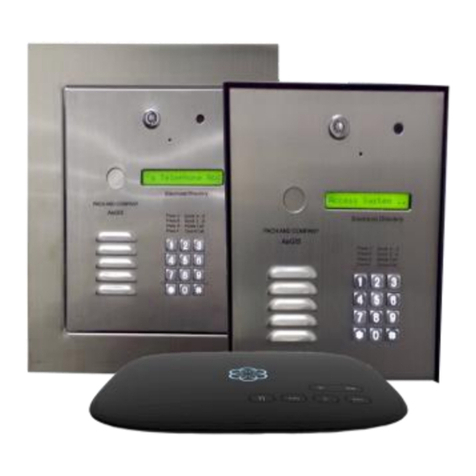
Select Engineered Systems TEC Series User manual

TEC Series v 3.2X
Page First
TEC Series
Telephone Access
Select
Engineered
Systems, Inc.
600TECMANUAL
Mar. 2015
TEC2
TEC4
TEC10

TEC Series v 3.2X
Page i
1 INTRODUCTION TEC SERIES 1
STANDARD FEATURES 1
CUSTOMIZING FEATURES 2
OPTIONS 3
ENVIRONMENT CONSIDERATIONS 4
ELECTRICAL REQUIREMENTS 4
TECHNICAL DATA 4
2 INSTALLATION 5
GENERAL 5
WIRE SPECIFICATIONS 5
TERMINAL WIRING HOOKUP CONNECTIONS 6
TERMINAL BARRIER STRIP CONNECTION DESCRIPTION 7
DIP SWITCH SETTINGS 8
SPEAKER SETTINGS 8
MICROPHONE SETTINGS 8
POWER SWITCH 9
3 ACCESSORY INSTALLATION 10
GENERAL 10
AVAILABLE OPTIONS 10
TWO (2) INPUT WIEGAND INPUT MODULE - VOLTAGE SELECT 11
FOUR (4) INPUT WIEGAND INPUT MODULE - VOLTAGE SELECT 11
WIRE SPECIFICATIONS 12
CARD READER WIRING 13
CARD READER SETTINGS 13
WIEGAND FORMAT 13
NIC CARD INSTALLATION 14
K2 RELAY FOR ENTRANCE 3 AND 4 15
K3 RELAY 16
ALARM AND CAMERA 16
TAMPER INPUTS 16
SHUNT USE FOR 4 WIEGAND INPUT MODULES 16
SERIAL PORT 17
PRINTER CONNECTION 17
MESSAGES 18
COMPUTER CONNECTION 18
TERMINAL CONNECTIONS 19
CURRENT LOOP WIRING 20
MODEM INSTALLATION 21
BOARD PLACEMENT 21
CONNECTIONS 21
SOFTWARE CONSIDERATIONS 21
MULTIPLE UNIT INTERFACE (MUI) 23
BOARD PLACEMENT 23
TWO MINUTE LOCKOUT 23
TECLITE 24
WIRING CONSIDERATIONS 24
LAMP CHANGING 24

TEC Series v 3.2X
Page ii
4 PROGRAMMING 25 - 68
QUICK KEYPAD EXAMPLE 25
TOUCH TONE 26
INITIALIZATION 27 - 49
MANAGER PASSCODE 50 - 68
PROGRAMMING CHOICES 50
KEYPAD 28
CODES / NAMES 30
ADD / FIND NAME 30
DELETING A CODE 30
DELETING A CODE FIELD 30
CODES USED 32
SHOW ALL CODES 32
SHOW ALL NAMES 32
ENABLE ACCESS GROUPS 32
ENTRY CONTROL 32
ENTRANCE X UNLOCK TIME 32
ENTRANCE X UNLOCK TONE 33
ENTRANCE X AUTO GROUP 33
ENTRANCE X LATCH TONE 33
ENTRANCE X SPECIAL RELAY ENABLE 33
SYSTEM PARAMETERS 34
TALK TIME 34
ALARM TIME 34
CODE LENGTH 34
PIN LENGTH 34
BACK BEEP 34
TONE DIAL 35
UNIT ID. OR RING COUNT 35
STRIKE OUTS 35
TITLE PAGE 35 - 36
COMMUNICATIONS SETUP 36
TERMINAL TYPE
36
RS 232 BAUD
37
PROGRAM PASSWORD 37
CONTROL PASSWORD
37
PIN ON ENTRANCE
37
SITE CODE
37
DIRECTORY ON / OFF
38
KEYPAD ON / OFF
38
SPEAKER TONE
38

TEC Series v 3.2X
Page iii
PROGRAMMING continued
CLOCK SETUP
38
SETTING TIME/DATE
39
SETTING TIME ZONES 39
SETTING HOLIDAYS
41
ACCESS LEVELS 42
SELECTING AN ACCESS GROUP 42
SELECTING AN ACCESS LEVEL
43
PROGRAMMING AN ACCESS LEVEL - TABLE
44
AUTOMATIC UNLOCK AND RELOCK BY TIME ZONE
44
EXAMPLE OF AN AUTOMATIC UNLOCK APPLICATION 44 - 45
TRANSACTION BUFFER INFORMATION
45 - 46
VIEW LOG
46
SEND LOG
46
BUFFER FREE
46
CLEAR BUFFER
46
CLEAR DATA
46
SET PARAMETERS 46
CLEAR TIME ZONES
46
CLEAR HOLIDAYS
46
CLEAR ACCESS LEVELS
47
CLEAR ACCESS GROUPS 47
CLEAR CORRUPT DATA
47
DISPLAY DATA
47
PRINT INFO
47
PRINT HOLIDAYS 48
PRINT ACCESS LEVELS 48
PRINT ACCESS GROUPS 48
DISPLAY TIME ZONE 49
DISPLAY HOLIDAYS 49
DISPLAY ACCESS LEVELS 49
DISPLAY ACCESS GROUPS 49
TERMINAL PROGRAMMING 50
GENERAL 50
MANAGER PASSCODE 51
PROGRAMMING CHOICES 51
CODES / NAMES 53
ADD / FIND NAME 53
DELETING A CODE 53
DELETING A CODE FIELD 53
CODES USED 54
SHOW ALL CODES 54
SHOW ALL NAMES 54
ENABLE ACCESS GROUPS 55
ENTRY CONTROL 55

TEC Series v 3.2X
Page iv
TERMINAL PROGRAMMING continued
ENTRANCE X UNLOCK TIME 55
ENTRANCE X UNLOCK TONE 55
ENTRANCE X AUTO GROUP 56
ENTRANCE X LATCH TONE 56
ENTRANCE X SPECIAL RELAY ENABLE 56
SYSTEM PARAMETERS 57
TALK TIME 57
ALARM TIME 57
CODE LENGTH 57
PIN LENGTH 57
BACK BEEP 57
TONE DIAL 57
UNIT ID. OR RING COUNT 58
STRIKE OUTS 58
TITLE PAGE 58
COMMUNICATIONS SETUP 59
TERMINAL TYPE
59
RS 232 BAUD
59
PROGRAM PASSWORD
59
CONTROL PASSWORD
59
PIN ON ENTRANCE
59
SITE CODE
60
DIRECTORY ON / OFF
60
KEYPAD ON / OFF
60
SPEAKER TONE
60
UPDATE LCD (TECVISION ONLY) 60
CLOCK SETUP
60
SETTING TIME/DATE
60
SETTING TIME ZONES
61
SETTING HOLIDAYS
62
ACCESS LEVELS 63
SELECTING AN ACCESS GROUP
63
SELECTING AN ACCESS LEVEL
64
PROGRAMMING AN ACCESS LEVEL - TABLE
65
AUTOMATIC UNLOCK AND RELOCK BY TIME ZONE 65
EXAMPLE OF AN AUTOMATIC UNLOCK APPLICATION 65 - 66
TRANSACTION BUFFER INFORMATION 66
VIEW LOG
66
SEND LOG
66
BUFFER FREE
67
CLEAR BUFFER
67
CLEAR DATA
67

TEC Series v 3.2X
Page v
TERMINAL PROGRAMMING continued
SET PARAMETERS 67
CLEAR TIME ZONES
67
CLEAR HOLIDAYS
67
CLEAR ACCESS LEVELS
67
CLEAR ACCESS GROUPS 67
CLEAR CORRUPT DATA
67
DISPLAY DATA 68
PRINT INFO
68
PRINT HOLIDAYS 68
PRINT ACCESS LEVELS 68
PRINT ACCESS GROUPS 68
DISPLAY TIME ZONE 68
DISPLAY HOLIDAYS 68
DISPLAY ACCESS LEVELS 68
DISPLAY ACCESS GROUPS 68

TEC Series v 3.2X
Page 1
The TECHF/50, through TECHF/2000, are automatic call , entry and card reader control
systems.
The TEC units operate and program identically. In this manual, the term "TEC" will be used
interchangeably to refer to any type of unit. The TEC series line includes a 2 line display LCD display
called the TEC2, a 4 line LCD display called the TEC4, and a 10 name LCD display called the TEC10.
Except for the display size or housing, the electronics are identical. This programming manual is valid
for any model TEC system. Where there are differences, a table will show those differences like this:
1 INTRODUCTION to the TEC SERIES
TEC10
The TEC 2 display message is: The TEC 10 display message is:
PRESS # TO VIEW
DIRECTORY PRESS # TO VIEW
DIRECTORY
PRESS # TO SEE NAMES
ON THE DIRECTORY
THEN DIAL THE CODE
TO THE RIGHT OF NAME
The TEC 4 display message is:
PRESS # TO VIEW
DIRECTORY
PRESS # TO SEE NAMES
THEN DIAL THE CODE
PRESS AND HOLD # FOR
FAST SCROLLING > Z
PRESS AND HOLD * FOR
FAST SCROLLING A <
TEC2
TEC4

TEC Series v 3.2X
Page 2
• 1 - 6 digit directory codes field programmable.
• 0 - 6 digit entry codes Personal Identification Number (PIN) field programmable.
• One card per Directory code.
• Up to 2,000 cards may be used
• Card reader control module for either 2 or 4 entrances using these technologies:
1) Wiegand, swipe, insert, or keypad.
2) Proximity, RF Transmitter, Bar Code (Wiegand code only), Long Range Proximity.
• Transaction Buffer (up to 1580 transactions depending on code size and options).
• Clock & Calendar, timed lock and unlock.
• Time Zones, Access Levels, and Holidays.
Resident activated door/gate release via Touch-Tone™ number (1-9), field programmable on all
entrances.
• Voice mail response capability. (Keypad active after unit calls out, programmed from TEC).
• Crystal controlled tone detection for short burst 50 MS tone.
• Speaker Listen-in.
• Memory Capacities:
50/125/250/500/1000/2000 for residents telephone numbers and names in directory.
• Dials out either Touch-Tone™ or rotary - field programmable.
• Dials up to 14 digit phone numbers.
• Unit will mute tones in speaker during dialing.
• Unit will not accept Touch-Tone™ signals through the microphone.
• Two line 16 character per line LCD display. (TEC 2 Series) Displays one name.
• Four line 20 character per line LCD display. (TEC 4 Series) Displays 4 names.
• Four line 40 character per line LCD display. (TEC 8 & Advantec Series) Displays 8 names.
• Programmable without opening cabinet, via keypad, RS-232, or Modem with Selcom 7 Software
• Talk time field programmable from 1 - 99 min.
• Postal lock capability included.
• Request to exit input for all entrance control relays.
• Entry code attempts (strike out) programmable from 0 - 9.
• Non-volatile memory, retains data even when power is removed.
• Surface or semi-flush mounting.
• Remote Entrance relay activation.
• Latching Entrance relays (with Remote Control Password).
• Programmable background "beep" to indicate call placed from telephone entry unit.
• Personal Identification Number (PIN code). Extra PIN codes above unit capacity.
• Remote Touch-Tone™ Entrance Relay Control.
• Manager Password (First three digits of Program Password).
• Battery charging circuitry.
STANDARD FEATURES:
STANDARD CUSTOMIZING FEATURES
1 INTRODUCTION

TEC Series v 3.2X
Page 3
• Hide Name Feature. Allows people to dial a code without displaying name on directory.
• Two minute modem lockout time.
• Dynamic scrolling, based on number of phone numbers programmed (See table below).
(Scrolls after key is held more than 4 seconds).
STANDARD CUSTOMIZING FEATURES continued
BASIC OPERATION:The TEC is a microprocessor based device that allows entering from 1 - 6
digits on the front keypad. It then automatically dials the phone number programmed into memory.
The TEC provides a relay output for controlling doors, gates, elevators or any device actuated by a
contact closure or contact opening. The TEC has a programmable 1 to 99 minute talk-time limit. It
provides warning tones near the end of talk time.
The TEC will dial out either pulse (rotary) or Touch-Tone™ via programming selection. While
the TEC dials, the speaker disconnects, keeping the dialed phone number confidential.
The TEC has an (optional) relay (OPTK3R). This can (depending on the options ordered and
the programming) be configured as either: a third door control, an alarm and off-hook control relay, or
Door 1 & 2 shunt relay and door sense. Calling the TEC from a Touch-Tone™ telephone will allow
the user to control the output relays by pressing a Touch-Tone™ number. (Factory default is 6 to
actuate relay 1.) When the user calls the TEC, the TEC will ring, go off hook and send a ¼ second
tone. Entering the proper control password will allow access to the output relays. This also allows
relay latching functions.
The (Optional) 12 volt DC .8 A/hr internal battery (B12V) is recommended for line stability. The
battery is NOT required for memory storage. SES supplies the TEC with a 16.5 vac transformer that
will operate the TEC and recharge the optional internal battery.
DO NOT CONNECT ANY OTHER DEVICES TO THE BATTERY.
TEC 2 TEC 4 TEC 10
1 to 30 Names scrolls by 2's scrolls by 4's scrolls by 8's
33 to 100 Names scrolls by 5's scrolls by 8’s scrolls by 16’s
101 to 260 Names scrolls by 10's Scrolls by 16’s scrolls by 32’s
261 or more Names scrolls by 15’s scrolls by 48's scrolls by 96's
Dynamic Scrolling Table,
• Card reader control module for either 2 or 4 entrances using these technologies
•
56.6K Baud modem
• Wiegand, swipe, insert or keypad
• Proximity, RF Transmitter, Bar Code (Wiegand Code Only), Long Range Proximity
• Clock & Calendar, timed lock and unlock with Time Zones Access Levels and Holidays
• Printer capability (RS-232 port) , Current Loop or NIC Interface to printer, terminal or computer
• (Baud rates to printer and/or remote terminal (CRT)) 300, 600, 1200, 2400, 4800, 9600, 19200
• Current loop 300, 600, 1200, 2400, 4800, 9600 to 2000 feet.
• Third signal relay with two modes of operation:
1.) for CCTV activation, alarm output, tamper input)
2.) or for control of a third door (timed and latched functions).
• Multiple TEC's (2 - 8 depending on programming mode) can share same telephone line, via
multiple unit interfaces (OPTKMUI).
• Local ringer capability.
OPTIONS:

TEC Series v 3.2X
Page 4
Indoor or Outdoor: The standard TEC housing is suitable for indoor or outdoor installations. For
semi-flush installations, contact SES about the optional flush ring (OPTFLR). For surface mount
installations, contact SES for the optional trim ring (OPTSL-2). Optional pedestal mounts for curb
(PST236), or street (PST242).
ENVIRONMENTAL CONSIDERATIONS
ELECTRICAL REQUIREMENTS
• POWER INPUT: 16.5 VAC 20 VA UL LISTED TRANSFORMER (PROVIDED).
• EMERGENCY BATTERY: 12V .8 A/HR GEL CELL ON CONSTANT CHARGE (OPTIONAL).
• TELEPHONE LINE: VOICE GRADE RJ-11C JACK.
• SHIPPING WEIGHT: APPROXIMATELY 15 LBS. (TEC 2 & 4 only)
• CONSTRUCTION: FRONT PANEL: 16 GA. STAINLESS STEEL (TEC 2, 4 & 8 only).
• BACK BOX: PAINTED CHEMICALLY TREATED ALLOY
ALUMINUM.
• OPERATING ENVIRONMENT: TEMPERATURE: -20º F (-6ºC) TO +160ºF (70ºC)
• RELATIVE HUMIDITY: 5% - 95% NON-CONDENSING.
• ` VISION TEMPERATURE: -32º F (-0ºC) TO +122ºF (50ºC)
• RELATIVE HUMIDITY: 5% - 95% NON-CONDENSING.
•
• RELAY OUTPUT: FORM C DRY CONTACTS 24V @ 3 AMP.
• MOUNTING: SURFACE OR SEMI-FLUSH.
• MEMORY TYPE: NON-VOLATILE.
• TONE DETECTION: CRYSTAL CONTROLLED, WILL DETECT SHORT BURST 50
MILLISECOND TONE.
Power: The TEC uses 16.5 volt ac 50/60 Hz. SES supplies a 16.5 vac transformer with each
purchase in the U.S. only. The installer may choose to provide their own 12 volt 300 - 600 ma. DC
supply (for TEC only depending on model type, will not also power card readers). YOU CAN NOT
USE AC TRANSFORMER AND DC SUPPLY AT THE SAME TIME.
Ground: The TEC must be connected to a good earth ground with at least # 16 ga. stranded wire.
This wire MUST be a minimum of 16 ga. connected to a ground rod or cold water pipe at one end,
and to the provided ¼-20 bolt at the TEC end. The maximum wire length is 50 feet. Surge damage
protection built into TEC diminishes if you do not provide an adequate earth ground.
Relay capabilities: 24 volts AC or DC at 3 amp. Form "A" (N/O) OR Form “B” (N/C) contacts are
present for all relays.
Gate controllers: Some solid-state gate controllers react to the over-voltage protection devices used
on all SES products. This is a gate controller dependent problem. The symptom is an intermittent
gate open, or gate stuck open condition, sometimes occurring after using the latching function. If this
occurs, add an external relay controlled by the TEC output relay contacts to your gate system
(OPTKFRMC) . This will help isolate the contacts going to your solid state gate controller from the
over-voltage protection devices.
Pedestal Mounting: For installations where the TEC will be mounted on a pedestal, a ground rod
MUST be installed immediately adjacent to the TEC. In addition, a ground wire of at least # 14
gauge wire must be used from the ¼-20 ground lug mounted in the back of the TEC back-box to the
ground rod clamp. This ground wire is to be no more than 25 feet in length, and should have no
sharp bends in the wiring.
TECHNICAL DATA
1 INTRODUCTION

TEC Series v 3.2X
Page 5
1. Never install telephone wiring during a lightning storm.
2. Never install telephone jacks in wet locations unless the jack is specifically designed for wet
locations.
3. Never touch un-insulated telephone wires or terminals unless the telephone line has been
disconnected at the network interface.
4. Use caution when installing or modifying telephone lines.
Installation of TEC requires coordination with your telephone company. SES recommends that a
Touch-Tone™ line be installed to allow much faster dialing. If a Touch-Tone™ line is not
available, the TEC can be reprogrammed to dial out pulse (rotary) signals.
The phone company may require the following information:
The ringer equivalence number.
The FCC registration number.
These numbers are on the label on the inside door of the TEC.
The desired location of the telephone jack must be given to the phone company at the
time you order the phone line.
INSTALLATION INSTRUCTIONS
INSTALLATION PROCEDURE
1) The TEC should be mounted approximately 52 inches above finished floor to the center of the
TEC. For drive up applications, TEC should be mounted approximately 42" - 48" above finished
flooring to the center of TEC. Hand set units should be mounted 40" - 46" above finished floor to
help comply with the Americans with Disabilities Act (ADA).
2) To surface mount the TEC, mount the back-box using the holes provided.
3) To flush mount the TEC, cut a hole the size of the back box (9 ½" wide X 13 ½" high) in the wall.
Mount the TEC in the hole. LEAVE ½" CLEARANCE FROM THE REAR OF THE DOOR TO THE
WALL SO THE DOOR WILL OPEN.
4) We recommend an optional weather hood (WH) when mounting TEC in a stand-alone application,
to protect it from direct exposure to rain and snow.
5) The TEC MUST BE AT EARTH GROUND POTENTIAL. Connect a #16 stranded or larger wire
from the ground lug mounted on the back-box of the TEC to a cold water pipe or other suitable
ground. This wire should be less than 50 feet in length.
6) Connect the wires for the power connections to TBS-5 and TBS-6, as shown on Pg. 7. Connect
the other ends of the wires to the screws on the supplied transformer (16.5 vac).
NOTE THE FOLLOWING BEFORE ATTEMPTING ANY INSTALLATION:
Recommended wire gauge is as shown: 16 ga. up to 50 feet.
14 ga. up to 100 feet.
For unusual distances or requirements please consult factory.
7) The ouput contacts for entrances 1 & 2 are Form A or B. If you are using the N.O. contacts on the
entrance 1 relay, connect the wires from the controlled device to TBS-13 and TBS-14, as shown on
Pg. 6. To use the N.C. contacts, move the jumpers on J201-1&2 as shown on Pg 8. Wire
entrance 2 relay to TBS-15 and TBS-16 and J202-1&2 in the same manner. For Entrance 3 & 4
relay connections, see Entrance 3 & 4 control on Page 15.
NOTE: THE RELAY CONTACTS ARE RATED FOR 24 VOLTS AC OR DC AT 3 AMPS MAXIMUM.
8) Connect the modular plug for the telephone line to the RJ-11 jack provided by the phone company.
No other telephones or equipment should be on this line. If attaching multiple TEC's to a single
phone line, the optional OPTKMUI (Multiple Unit Interface) may be purchased. For further
information, see Section on Page 23.
9) All wire openings, or any penetration of the TEC enclosure should be sealed in accordance with
the National Electrical Code or local ordinances.
10)This completes the installation.
INSTALLATION INSTRUCTIONS

TEC Series v 3.2X
Page 6
WIRING HOOKUP CONNECTIONS
TBS = TERMINAL BARRIER STRIP
INSTALLATION INSTRUCTIONS
PHONE LINE
TBS-2
TBS-3
TBS-5
TBS-6
TBS-11
Entrance 1
TBS-16`
MODULAR PLUG
TO RJ-11 JACK
TBS-12
SES
TRANS-
FORMER
POWER 16 GA. TWIST
50 FEET MAX DIST.
ELECTRIC DOOR STRIKE
DOOR STRIKE
N.O. DRY CONTACT
FOR GATE CONTROLLER
OR ELEVATOR INPUT
TBS-11
TBS-12
N.C. DRY CONTACT FOR
FAIL SAFE STRIKE OR MAG LOCK
TO DEVICE
TBS-12
TBS-13
TRANS-
FORMER
AS
NEEDED
TRANS-
FORMER
AS
NEEDED
Entrance 2
TBS-14
TBS-14
TBS-15
TBS-15
TBS-15
16.5VAC
20VA

TEC Series v 3.2X
Page 7
TERMINAL BARRIER STRIP CONNECTIONS
USE 16 GA. OR LARGER
TEC UNIT MUST BE GROUNDED
SES SUPPLIED TRANSFORMER 16 GA. TO 50 FT.
SES SUPPLIED TRANSFORMER 16 GA. TO 50 FT.
ENTRANCE #1 N.O.
or (Jumper 201-1&2)
ENTRANCE #1 N.C.
COMMON TO BATTERY AND REX INPUTS
ENTRANCE #2 N.O.
or (Jumper 202-1&2)
ENTRANCE #2 N.C.
FOR ALL SHIELDS
Entrance 1 and 2 Relays can be reconfigured to Normally Closed
Contacts. See page 8 for details on jumper changes.
BACKUP BATTERY + (POSITIVE)
INSTALLATION INSTRUCTIONS
TELEPHONE LINE CONNECTS HERE
TELEPHONE LINE CONNECTS HERE
N.O. REQUEST TO EXIT #1
N.O. REQUEST TO EXIT #2
COMMON TO BATTERY AND REX INPUTS
COMMON TO BATTERY AND REX INPUTS
Not Used
16.5 VAC
20 VA

TEC Series v 3.2X
Page 8
RESET
ALWAYS ON
2RDR=OFF / 4RDR=ON
SPKR ENABLE
PROGRAM ENABLE
CARD DIAG.
TecVision ENABLE
ALWAYS OFF FACTORY
SETTINGS
DO NOT
CHANGE
DIP SWITCH (SW1) SELECTION DESCRIPTIONS
— PROGRAM ENABLE
— SPKER ENABLE
— ALWAYS OFF
— ALWAYS OFF
— CARD DIAG.
— 2 RDR-OFF/ 4RDR-ON
— ALWAYS ON
— RESET
SPEAKER AND MICROPHONE ADJUSTMENTS
MORE
LESS
LESS
MIKE
SENS
SPEAKER
VOLUME
MORE
INSTALLATION.
Entrance 1
Shown N/O Move both
jumpers for each to
make N/O
Shown N/C Move both
jumpers for each relay
to make N/C
Entrance 2
Relay Jumper Selections
(J201-1&2 for Entrance 1)
(J202-1&2 for Entrance 2)
J201 1&2J202 1&2
NOTE:
MIKE SENSITIVITY AND
SPEAKER VOLUME
INTERACT WITH EACH
OTHER. IMPROPER
ADJUSTMENT WILL
ADVERSELY AFFECT
PERFORMANCE AND/OR
OPERATION.

TEC Series v 3.2X
Page 9
POWER SWITCH LOCATION
POWER SWITCH
TURN OFF BEFORE
INSTALLING OR
REMOVING
ACCESSORIES.
POWER
CONNECTOR
PHONE LINE
POLYSWITCHES
POWER LED

TEC Series v 3.2X
Page 10
ACCESSORIES OVERVIEW
Although some options are not shown, available options are:
• External Card reader(s) input (2 or 4 Readers)
• Wiegand, Proximity, RF Transmitter, Barcode (Wiegand output).
• Several reader technologies using Wiegand format signals are available, including Wiegand,
Proximity, RF Transmitter, and Long Range Proximity Readers. Wiegand output keypad
controllers also may be used in some situations. Contact the factory for particulars on Wiegand
output keypads.
• Second signal relay (OPTK2R) has functions for shunt activation and 2 REX inputs.
• Third signal relay (OPTK3R) has functions for CCTV activation, alarm output and 2 tamper inputs.
• Standby batteries (OPTB12V).
• 56k baud modem (OPTKMODEM56).
• RS-232 port or Current Loop for printer, terminal or computer connections (OPTKPRT)
• Serial Baud rates to printer and/or remote terminal (CRT) 300, 600, 1200, 2400, 4800, 9600,
19200
• Current Loop baud rates- 300, 600, 1200, 2400, 4800, 9600
• NIC Card for Networking connections for monitoring and programming
• Multiple units can share same telephone line, via MUIs (OPTKMUI).
• Two minute "sleep" function to allow programming up to 4 TECS with modems.
•Third signal relay (OPTK3R) has functions for CCTV activation, alarm output and 2 tamper inputs.
•
••
•Lighted Hood for greater night time visibility
To NIC2

TEC Series v 3.2X
Page 11
WIEGAND INPUT MODULES
The TEC OPTIONALLY can be equipped with two or
four internal card reader inputs. The card reader modules work
with 26 or 30 bit Wiegand format bit streams. There are no LED
drive indicator signals on the 4 door reader. Belden 9941 is
used to connect readers to the card reader modules.
There are jumpers on the card reader board to select 5 or
12 volts for various reader types. Many WIEGAND swipe,
insert or key readers are 5 volts. Many RF, PROXIMITY and INFRARED readers are 12 volts. If the
readers and the card option were purchased together, this has already been configured. If not, see the
diagram to select the appropriate card reader voltage setting. Check with the manufacturer of your
card reader for correct voltage selection.
Note that the card reader and relay assignments cannot be mixed. Card Reader 1 will
ALWAYS control the first relay. This is the relay on the terminal barrier strip to the left of the mother
board. Card Reader 2 will ALWAYS control the 2nd relay output on the terminal barrier strip to the left
of the mother board. The maximum distance for WIEGAND readers is 500 feet. Belden #9941 or
close equivalent must be used for card reader signals. The maximum distance for RF, PROXIMITY, or
INFRARED readers is 100 feet, using Belden #9941. For distances up to 500 feet use Belden #
83656, or close equivalent.
The maximum power consumption available for using on-board power supply is 125 ma. per
reader. For readers with greater power requirements, an external power supply MUST be used.
READER1CONTROLSOUTPUTRELAY
ONTBS-13 &TBS-14ONLY
READER3CONTROLSK2 OUTPUTRELAYONLY
SEE SECTION12.0ENTRANCECONTROL
WIEGAND
BARIUM
FERRITE
OR
PROXIMITY
4
12 3
READER2CONTROLSOUTPUTRELAY
ONTBS-15 &TBS-16ONLY
READER4CONTROLSK2 OUTPUTRELAYONLY
SEE SECTION12.0ENTRANCECONTROL
Jumper selectionistypicalfor all4
reader modules
.
CARD READER VOLTAGE SELECT
READER 1 CONTROLS OUTPUT RELAY
ON TBS-13 & TBS-14 ONLY
WIEGAND
BARIUM
FERRITE
OR
PROXIMITY
1
2
READER 2 CONTROLS OUTPUT RELAY
ON TBS-15 & TBS-16 ONLY
Jumper selection is typical for both
reader modules
.
ACCESSORY INSTALLATION
Reader 1 Common (Black)
Reader 1 LED (Brown)
Reader 1 D0 (Green)
Reader 1 D1 (White)
Reader 1 Power (Red)
Reader 2 Common (Black)
Reader 2 LED (Brown)
Reader 2 D0 (Green)
Reader 2 D1 (White)
Reader 2 Common (Red)
For older style readers still in use, above are
the jumper settings for voltage select.
(OPTIONAL)
(OPTIONAL)

TEC Series v 3.2X
Page 12
GROUNDING CARD READER WIRING
NOTE: DO NOT WIRE ANY PORTION OF THE CARD READER "HOT." REMOVE
ALL POWER BEFORE WIRING ANYTHING TO THE CARD READER.
WIEGAND CARD
READER
BLACK COM
GREE N D0
WHITE D1
RED +5 VDC
OR +12 VDC
BELDEN9941 100 FEET MAX DISTANCE
BELDEN83656 500 FEET MAX DISTANCE
TAPE SHIELD
THIS END
BARIUM
FERRITE
READER
BELDEN9941
500 FEET MAX DISTANCE
CONNECT SHIELD
TO GROUND LUG
READER 1 2 3 4
IJACKET INSULATION
RED
BLK
GRN
WHT
BRN
SHIELD BRAID
Strip away 3 inches from the outer jacket, as
shown at left.
JACKET INSULATION RED
BLK
GRN
WHT
BRN
SHIELD BRAID
Attach an insulated #18 gauge stranded
wire to the shield with a wire nut. Allow
enough length for the insulated #18 wire to
reach the ground lug in the back of the TEC
back box.
Tape the shield from the cable to the wire
nut to prevent shorting to any components
on the TEC PC board.
Poke a hole in the braid as shown at left.
Spread the braid open, so the conductors
are visible. Peel the conductors out, taking
care not to damage the insulation on the
conductors.
JA CK ET IN S U L AT IO N
R E D
B LK
G RN
W H T
B RN
S HIE L D B RAID
W I R E N UT
BLACK COM
GREEN D0
WHITE D1
RED +5 VDC
OR +12 VDC
UNUSED
BROWN LED
READER 2 1
ACCESSORY INSTALLATION
(OPTIONAL)

TEC Series v 3.2X
Page 13
CONNECTING CARD READER WIRING
BLK
RED
GRN
WHT
WIRE
READER 1 2 3 4
Strip 3/16" insulation from the conductors. Fold the stripped portion of the conductor over the
insulated portion. Insert the wire in the clamps of the screw terminals on the card reader board and
clamp down by screwing the terminal screw tightly. This ensures a good mechanical connection and
an electrical connection that will keep the small wires from breaking.
SITE CODE
To keep a card (for example card number 12345) from being used from another facility, a Site Code is
set in the TEC. This is the same as a Facility Code would be in a commercial card reader installation.
Set the Site Facility Code using Pg. 37
If the Site code (of the cards) is not known, turn on #5 on the dip switch on the main PC board.
This will display card errors on the LCD screen on the front door. Swipe a card through a reader and
read the site code error information on the LCD display to determine the Site code. After the Site
code is entered turn switch 5 off, to keep swiped card numbers confidential.
To have the TEC unit ignore the site code completely, enter 255 as a site code. This
diminishes the security of the facility, as a card from some other facility that was coincidentally the
same number as a valid card, could operate the reader. This is sometimes necessary when mixing
card technologies on a site, but should only be done as a last resort.
SETTING WIEGAND FORMAT
While there are several Wiegand output formats, the two used by SES are 26 and 30 bit Wiegand
output. The factory default from SES is 30 bit output. To set the bits to 26, enter 260 as a site code
number (See Pg 37) To set the bits to 30, enter 300 as a site code number. Neither of these numbers
will change the existing Site code.
ACCESSORY INSTALLATION
As the above drawing shows, grounding the card reader correctly is very important. Since the
ground lug for the TEC is near the top of the unit, take care to avoid shorting the card reader cable
shield to components on the mother board.
(OPTIONAL)

TEC Series v 3.2X
Page 14
NIC2 CARD
The NIC (Network Interface Card) provides a
plug-in TCP/IP interface for all CAT and TEC
products
• TCP/IP network compatible ONLY.
• Compatible with all CAT products.
• Compatible with TEC products
running Selcom 7 or newer *
•Compatible with TEC1.
• Requires the end user to have a
qualified network manager for setup.
The SES Network Interface is used to provide a Programming and Data connection to a SES CAT or
TEC Telephone Access Controller through a local area network. The SES Network Interface
provides for conversion of the standard serial interface in the SES CAT or TEC controller to a
TCP/IP connection. All portions of the connection must operate at the same speed and connectivity
settings. We are pre-setting the selections to 9600 baud, 8 bits, no parity, 1 stop bit.
Each interface is provided with a unique hardware address. The network system administrator
provides an IP address that is assigned to the unique hardware address. Each SES Network
Interface is then assigned a unique port address on the network. A standard range of port addresses
is provided, that are normally not used in most networks, but the actual address(es) used should be
cleared by and approved by the network system administrator.
The Com Port Re-Director provides a means of using the IP address as a directed serial com port.
An unused port number is chosen in the computer and assigned to the IP address of the SES CAT
or TEC unit. The actual address(es) used should be cleared by and approved by the network system
administrator. The redirected comm port is then selected in older versions of Selcom Software
(Selcom Secured 6 or older) for that SES CAT or TEC unit. Selcom Secured 7 and newer can
directly address TCP/IP addresses and a comm port redirector is not required.
See the NIC2 Card Instruction
for further Info.
(OPTIONAL)
This manual suits for next models
9
Other Select Engineered Systems Intercom System manuals
