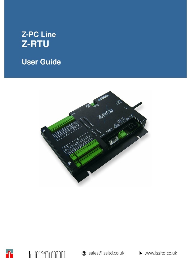
Seneca S6001 User manual

ORIGINAL INSTRUCTIONS
USER MANUAL
S6001
Pump controller


Doc. MI004620
S6001 Pump controller
Rev. 0
www.seneca.it 3 / 122
ALL RIGHTS RESERVED. NO PART OF THIS PUBLICATION CAN
BE REPRODUCED WITHOUT PREVIOUS AUTHORIZATION.
User Manual
CONTENTS
1 Introduction .......................................................................................................................................................7
1.1 Identicationdataofthemanual.................................................................................................................7
1.2 Purposeanduseofthemanual..................................................................................................................7
1.3 Consultationofthemanual.........................................................................................................................7
1.4 Glossary .....................................................................................................................................................8
1.5 Formulationofintellectualpropertyrights...................................................................................................9
2 Product Description.........................................................................................................................................10
2.1 GeneralDescription..................................................................................................................................10
2.1.1 RTU................................................................................................................................................... 11
2.1.2 HMI ...................................................................................................................................................14
2.2 Intended use.............................................................................................................................................14
2.3 Reasonablyforeseeableincorrectuse .....................................................................................................15
2.4 Technicalcharacteristics...........................................................................................................................16
2.4.1 Mechanicaltechnicalcharacteristics.................................................................................................16
2.4.1.1 RTUmechanicaltechnicalcharacteristics ................................................................................16
2.4.1.2 HMImechanicaltechnicalcharacteristics .................................................................................17
2.4.2 Electricaltechnicalcharacteristics ....................................................................................................17
2.4.2.1 RTUelectricaltechnicalcharacteristics ....................................................................................17
2.4.2.2 HMIelectricaltechnicalcharacteristics .....................................................................................19
2.4.3 Environmentalcharacteristics...........................................................................................................21
2.4.3.1 RTUenvironmentalcharacteristics ...........................................................................................21
2.4.3.2 HMIenvironmentalcharacteristics............................................................................................21
2.5 Congurations ..........................................................................................................................................21
2.6 Residualrisks ...........................................................................................................................................22
3 Installation .......................................................................................................................................................23
3.1 Assembly..................................................................................................................................................23
3.1.1 Assemblywarnings...........................................................................................................................23
3.1.2 Assemblyinstructions .......................................................................................................................23
3.1.2.1 RTUassemblyinstructions .......................................................................................................23
3.1.2.2 HMIassemblyinstructions........................................................................................................25
3.2 Electricalconnections...............................................................................................................................25
3.2.1 Warningsonelectricalconnections...................................................................................................25
3.2.2 Instructionsforelectricalconnections...............................................................................................26
3.2.2.1 Conguration1andConguration2 .........................................................................................27
3.2.2.2 Conguration3andConguration4 .........................................................................................32
3.2.2.3 Conguration5andConguration6 .........................................................................................37
3.2.2.4 Conguration7andConguration8 .........................................................................................42
3.3 Otherconnections ....................................................................................................................................46
3.3.1 ConnectionbetweenRTUandHMI ..................................................................................................46
3.3.2 Connectiontoserialports .................................................................................................................46

Doc. MI004620
S6001 Pump controller
Rev. 0 www.seneca.it
4 / 122 ALL RIGHTS RESERVED. NO PART OF THIS PUBLICATION CAN
BE REPRODUCED WITHOUT PREVIOUS AUTHORIZATION.
User Manual
3.4 HMIConguration.....................................................................................................................................47
3.4.1 Pressure/owcongurationwizard ...................................................................................................47
3.4.2 Levelcongurationwizard ................................................................................................................52
3.5 Testing ......................................................................................................................................................57
4 Use..................................................................................................................................................................58
4.1 HMI description.........................................................................................................................................58
4.1.1 Loginpage ........................................................................................................................................61
4.1.1.1 Usertype...................................................................................................................................61
4.1.2 “SENECA”page................................................................................................................................62
4.1.3 “Pumps”page ...................................................................................................................................62
4.1.3.1 “Individualpump”screen...........................................................................................................64
4.1.4 “Alarms”page ..................................................................................................................................64
4.1.4.1 “AlarmLog”screen ...................................................................................................................66
4.1.5 “Report”page....................................................................................................................................66
4.1.6 “Trend”page .....................................................................................................................................68
4.1.6.1 “Historicaltrend”screen............................................................................................................69
4.1.7 “Setpoint”page ................................................................................................................................71
4.1.7.1 “Set point” screen......................................................................................................................72
4.1.7.2 “Pumpthresholds”screen.........................................................................................................73
4.1.7.3 “Pumpparameters”screen .......................................................................................................74
4.1.7.4 “Analoguethresholds”screen...................................................................................................75
4.1.7.5 “PIDparameters”screen...........................................................................................................76
4.1.8 “Settings”page..................................................................................................................................77
4.1.8.1 “System”screen........................................................................................................................78
4.1.8.2 “IOdigitaltype”screen..............................................................................................................79
4.1.8.3 “IOanaloguetype”screen ........................................................................................................84
4.1.8.4 “HMI properties” screen ............................................................................................................86
4.1.8.5 “Telecontrol”screen ..................................................................................................................92
4.2 Use instructions........................................................................................................................................94
4.2.1 Systemstart......................................................................................................................................94
4.2.2 Systemmanagement........................................................................................................................94
4.2.2.1 Trendexample ..........................................................................................................................94
4.2.3 Systemstop ......................................................................................................................................96
5 Diagnostics......................................................................................................................................................97
5.1 Alarmmanagement ..................................................................................................................................97
5.1.1 Alarmlist ...........................................................................................................................................97
5.2 Remoteconnections...............................................................................................................................106
5.2.1 RemoteconnectionviaSMS...........................................................................................................106
5.2.2 VPN Connection ............................................................................................................................. 112

Doc. MI004620-I
S6001 Pump controller
Rev. 0
www.seneca.it 5 / 122
ALL RIGHTS RESERVED. NO PART OF THIS PUBLICATION CAN
BE REPRODUCED WITHOUT PREVIOUS AUTHORIZATION.
User Manual
6 Systemupdate .............................................................................................................................................. 114
6.1 RTUsoftwareupdate.............................................................................................................................. 114
6.2 HMIsoftwareupdate .............................................................................................................................. 114
7 Listofgures................................................................................................................................................. 117
8 Listoftables ..................................................................................................................................................120

Doc. MI004620-I
S6001 Pump controller
Rev. 0 www.seneca.it
6 / 122 ALL RIGHTS RESERVED. NO PART OF THIS PUBLICATION CAN
BE REPRODUCED WITHOUT PREVIOUS AUTHORIZATION.
User Manual

Doc. MI004620-I
S6001 Pump controller
Rev. 0
www.seneca.it 7 / 122
ALL RIGHTS RESERVED. NO PART OF THIS PUBLICATION CAN
BE REPRODUCED WITHOUT PREVIOUS AUTHORIZATION.
User Manual
11 INTRODUCTION
1.1 IDENTIFICATION DATA OF THE MANUAL
Theidenticationdataofthemanualcanbefoundinthefooterofthismanual.
1.2 PURPOSE AND USE OF THE MANUAL
ThisManualisanintegralpartoftheproductandisintendedforallpeoplewhoworkontheproductorinteractwith
theusersoftheproductitself.Itaimstoprovidealltheinformationnecessaryto:
°quicklyidentifyallpartsoftheproduct;
°denethetasks,capabilitiesandinterventionlimitsofthevarioususers;
°perform all the expected operations during the phases preceding the use, utilization, maintenance and
disposaloftheproduct;
°guaranteethesafetyandprotectionofthehealthofpersonnelwhoworkontheproductinvariousways;
°ensuretheefcientoperationoftheproduct.
Thismanualmustbereadcarefullyinitsentiretybeforecarryingoutanyoperationontheproduct.Incaseofdoubts
onthecorrectinterpretationoftheinstructionscontainedtherein,contactSENECAs.r.l.toobtainthenecessary
clarications.
ThisManualmustbekeptwithcarethroughoutthelifeoftheproductandmustaccompanytheproductitselfinallits
transfers,foranyreason,tootherusers.Itmustbeplacedneartheproduct,inaplaceprotectedfromatmospheric
agents,heat,humidityandcorrosiveagents,easilyaccessibleandknowntoallusers;itmustbeconsultedtaking
carenottodamageit,nottoremovepages,nottomodifyitscontentsinanyway.
If,asaresultofconstructivechangesthatentailachangeintheoperationoftheproduct,anupdateofthemanual
shouldbenecessary,SENECAs.r.l.willprovidetheCustomerwitharevisionoftheManualitselfthatwillreplace
thepreviousoneinallrespects.
1.3 CONSULTATION OF THE MANUAL
Insidethemanualtheinformationisorganizedin:
°chapters,
°subchapters,
°paragraphs,
°subparagraphs
andtheyareeasilytraceablebyconsultingtheSummaryatthebeginningoftheManualitself.
Todrawusers'attentiontothecorrectandsafeuseoftheproduct,thefollowinggraphicsymbolsareusedinthis
manual:

Doc. MI004620-I
S6001 Pump controller
Rev. 0 www.seneca.it
8 / 122 ALL RIGHTS RESERVED. NO PART OF THIS PUBLICATION CAN
BE REPRODUCED WITHOUT PREVIOUS AUTHORIZATION.
User Manual
Thesymbolisusedtoindicatedangeroussituationsforpeopleorsituationsthatmaycausedamage
totheproductorcompromiseitsefciency.
Thesymbolisusedtoindicateprohibitedoperations.
Thesymbolisusedtocallattentiontoparticularlyimportantinformation.
1.4 GLOSSARY
ROUTER
Network device that sends data packets between computer networks, for example through a LAN or a WAN
(Internet).
SWITCH
Networkdevicethatconnectsdifferentdevicesinacomputernetwork,usingaformofpacketswitchingtosend
datatothedestinationdevice.
HMI(HumanMachineInterface)
Theman-machineinterfaceisacomponentofthedevicesthatareabletomanagetheinteractionsbetweenman
andmachine.Theinterfaceconsistsofhardwareandsoftwarethatallowyoutotranslateuserinputsandturnthem
intosignalsforthemachines,whichinturnprovidetheresultrequestedbytheuserasoutput.
VPN(VirtualPrivateNetwork)
Virtualprivatenetworks(VPNs)arepoint-to-pointconnectionsonapublicorprivatenetwork,suchastheInternet.
AVPNclientusesspecialTCP/IP-basedprotocols,calledtunnellingprotocols,tomakeavirtualcalltoavirtual
portonaVPN server.Ina standardVPNdeployment,aclient initiatesapoint-to-pointvirtualconnection toa
remoteaccessserverovertheInternet.Theremoteaccessserverrespondstothevirtualcall,authenticatesthe
caller,andtransfersdatabetweentheVPNclientandtheorganization'sprivatenetwork.
WIZARD
Itisacomputerprocedure,generallyincorporatedinamorecomplexapplication,whichallowstheusertoperform
certain(usuallycomplex)operationsthroughaseriesofsuccessivesteps.
PROVIDER
ServicecompanythathascomputersconstantlyconnectedtotheInternetthroughspeciallines.Throughanormal
telephonelineandamodem,itispossibletoconnectsubscriberusers,thushavingaccesstothenetwork.

Doc. MI004620-I
S6001 Pump controller
Rev. 0
www.seneca.it 9 / 122
ALL RIGHTS RESERVED. NO PART OF THIS PUBLICATION CAN
BE REPRODUCED WITHOUT PREVIOUS AUTHORIZATION.
User Manual
AI(AnalogueInput)
Analogueinputacronym.
AO(AnalogueOutput)
Analogueoutputacronym.
DI(DigitalInput)
Digitalinputacronym.
DO(DigitalOutput)
Digitaloutputacronym.
CPU(CentralProcessingUnit)
Centralprocessingunit.Housedonthemicroprocessor,itmanagesandcontrolseverycomputeractivity,coordinates
thememoryandperipheralunitactivitiesandperformsallarithmeticandlogicaloperations.
PLC(ProgrammableLogicController)
Itisaprogrammableelectronicdevicecapableofinterpretingandexecutingtheinstructionsoftheprogramsstored
init,interactingwithacontrolcircuitthroughinputandoutputdevices.
SYSTEM
Setofpumps,dataacquisitionsensors,actuators,drives,etc.,fortheregulationofahydraulicquantity.
STATION
Systemset(asdenedin“1.6 General Description” on page 11)andplant.
1.5 FORMULATION OF INTELLECTUAL PROPERTY RIGHTS
All information, drawings, diagrams and anything else contained in this Manual and in the accompanying
documentationarecondentialinnature.Noneofthisinformationmaybereproducedorcommunicatedtothird
partieswithoutthepriorwrittenconsentofSENECAs.r.l.,whichisitsexclusiveowner.
TheonlyoneauthorizedtousethedocumentationinquestionistheCustomertowhomtheManualissuppliedas
anintegralpartoftheproduct,forthesoleexclusivepurposeofcorrectlycarryingoutalltheoperationsrelatedto
thevariousphasesofthelifecycleoftheproductitself.

Doc. MI004620-I
S6001 Pump controller
Rev. 0 www.seneca.it
10 / 122 ALL RIGHTS RESERVED. NO PART OF THIS PUBLICATION CAN
BE REPRODUCED WITHOUT PREVIOUS AUTHORIZATION.
User Manual

Doc. MI004620-I
S6001 Pump controller
Rev. 0
www.seneca.it 11 / 122
ALL RIGHTS RESERVED. NO PART OF THIS PUBLICATION CAN
BE REPRODUCED WITHOUT PREVIOUS AUTHORIZATION.
User Manual
22 PRODUCT DESCRIPTION
1.6 GENERAL DESCRIPTION
Theproduct,calledS6001Pumpcontroller,isacongurablesystemforthecontrolandadjustmentofapump
group,consistingofanumberofpumpsrangingfromaminimumof2toamaximumof6.
Intheremainderofthemanual,theS6001PumpControllerwillbereferredtoasthe“system”.
A
B
Fig. 1 S6001 Pump Controller
Thesystem(Fig. 1 on page 11)consistsof:
°S6001 RTU (A),congurablepumpsupplycontrolCPUmodule;
°7”HMIpanel(B),allowingtheuser’sinteractionwiththeCPUmoduleandthepumpgroupconnectedtoit.
IntherestoftheManual:
-theS6001RTUwillbecalled“RTU”;
-theHMIpanelwillbecalled“HMI”.

Doc. MI004620-I
S6001 Pump controller
Rev. 0 www.seneca.it
12 / 122 ALL RIGHTS RESERVED. NO PART OF THIS PUBLICATION CAN
BE REPRODUCED WITHOUT PREVIOUS AUTHORIZATION.
User Manual
1.6.1 RTU
Fig. 2 RTU
TheRTU(Fig. 2 on page 12)isequippedwith:
°supply(P11 - Fig. 2 on page 12),
°inputs/outputs (P2 - Fig. 2 on page 12),
°communicationports(P2, P3, P4 - Fig. 2 on page 12),
°signallingLEDs(P10 - Fig. 2 on page 12),
onwhichmoredetailedinformationisprovidedinthefollowingtables.
Reference/Terminal No. Description
P0/51,52,53 RTUsupply
Tab. 1 RTU supply
Terminal No. Description
1,2,3,4,5,6,7,8,9,10,11,12,13,14,15,16,17,18 Digitalinputs
37,38,39,40,41,42,43,44,45,46,47,48,49,50 Analogueinputs/outputs
71,72,73,74,75,76,77,78,79,80,81,82,83,84,85,
86,87,88,89,90,91,92,93,94 Relaydigitaloutputs
Tab. 2 RTU inputs/outputs
Reference/Terminal No. Description
P1 EthernetPort
P2/54,55,56 RS485 port (COM 4)
(P0) (P5)
(P4)(P6)(P2) (P3) (P7)(P8)(P9)
(P11)
(P4)
(P1)
(P10)

Doc. MI004620-I
S6001 Pump controller
Rev. 0
www.seneca.it 13 / 122
ALL RIGHTS RESERVED. NO PART OF THIS PUBLICATION CAN
BE REPRODUCED WITHOUT PREVIOUS AUTHORIZATION.
User Manual
Reference/Terminal No. Description
P3/57,58,59 RS485 port (COM 2)
P4 RS232 port (COM 1)
P5 USB port
P6 SDcardport
P7 SIMcardport
P8 Main3Gantennaconnector
P9 Diversity3Gantennaconnector
Tab. 3 RTU connector/port description
Port (P6 - Fig. 2 on page 12)isnotusedbythesystem.
Forfurtherinformation,pleasereferto“1.9.2 Electrical technical characteristics” on page 17.
Group Number Colour Status Meaning
DIGITAL INPUTS
(digitalinputs)
1,2,3,4,5,6,7,8,9,
10,11,12,13,14,15 Green ON High
OFF Low
DIGITAL OUTPUTS
(digitaloutputs) 1,2,3,4,5,6,7,8 Red ON High
OFF Low
3G PWR SIG.
(3Gsignalpower) 1,2,3,4,5,6 Yellow
ON Signalpresent
(6ON=Max)
OFF Signalabsent
(1Flashing=Min)
COM PORT COM2
(commonportCOM2) RX,TX Red Flashing RS485active
Red ON Connectioncheck
COM PORT COM4
(commonportCOM4) RX,TX Red Flashing RS485active
Red ON Connectioncheck
RUN(operation) 1 Red Flashing Working
LEVEL SWITCH
(levelswitch) L1,L2 Green
OFF,OFF(value0) Belowtheminimumlevel
ON,OFF(value1)
Includedbetweenthe
minimum and maximum
level
ON,ON(value2) Abovethemaximumlevel
Tab. 4 RTU signalling LED - operation

Doc. MI004620-I
S6001 Pump controller
Rev. 0 www.seneca.it
14 / 122 ALL RIGHTS RESERVED. NO PART OF THIS PUBLICATION CAN
BE REPRODUCED WITHOUT PREVIOUS AUTHORIZATION.
User Manual
FindbelowfurtherinformationonhowtheLEDsoperate:
°Atpower-up,duringtheloadingphase,alltheLEDs,withtheexceptionoftheCOMportLEDs,areON;when
thesystemisfullyoperational,theoperationLEDashes.
°The3G+signalpowerLED1ashes,insyncwiththeoperationLED,inthefollowingsituations:
−
theGSM/3G+networkisnotavailable(orthesignallevelistoolow);
−
theSIMisnotinserted;
−
themodemisnotpresent.
LED Status Meaning
3G+PWRGreen ON The3G+modemisON
STATyellow
ON NotrecordedontheGSMnetwork
Slowashing RecordedontheGSMnetwork
Fastashing PPPconnectionactive
Tab. 5 RTU signalling LED - Modem
1.6.2 HMI
1,2,3
P1
P3
P2
Fig. 3 HMI
TheHMI(Fig. 3 on page 14)isequippedwith:
°Powersupply(1,2,3 - Fig. 3 on page 14),
°communicationports(P1 - Fig. 3 on page 14),,
onwhichmoredetailedinformationisprovidedinthefollowingtables.

Doc. MI004620-I
S6001 Pump controller
Rev. 0
www.seneca.it 15 / 122
ALL RIGHTS RESERVED. NO PART OF THIS PUBLICATION CAN
BE REPRODUCED WITHOUT PREVIOUS AUTHORIZATION.
User Manual
Terminal No. Description
1,2,3 HMIsupply
Tab. 6 HMI supply
Port reference Description
P1 RS232 port
P2 EthernetPort
P3 USB port
Tab. 7 HMI port description
1.7 INTENDED USE
Thesystemisintendedforoneofthefollowingapplications:
°pressureadjustment;
°owadjustment;
°leveladjustment;
−
tanklling;
−
liftingfromtank.
Measuringthelevelcanbecarriedout:
°withoats;
°withalevelprobe;
°withoatsandalevelprobe.
1.8 REASONABLY FORESEEABLE INCORRECT USE
Any use of the system other than indicated in “1.7 Intended use” on page 15 and compliant with
theindicationsprovidedinthisManualistobeconsideredIMPROPERUSEandtheManufacturerdeclinesall
responsibilityinrelationtoanydamagecausedtopersonsorpropertyanddeemsthewarrantyoftheproductnull
andvoid.

Doc. MI004620-I
S6001 Pump controller
Rev. 0 www.seneca.it
16 / 122 ALL RIGHTS RESERVED. NO PART OF THIS PUBLICATION CAN
BE REPRODUCED WITHOUT PREVIOUS AUTHORIZATION.
User Manual
1.9 TECHNICAL CHARACTERISTICS
1.9.1 Mechanical technical characteristics
1.9.1.1 RTU mechanical technical characteristics
Fig. 4 RTU dimensions
Width 190mm
Depth 60mm
Height 105mm
Weight 720g
Tab. 8 RTU dimensions and weight

Doc. MI004620-I
S6001 Pump controller
Rev. 0
www.seneca.it 17 / 122
ALL RIGHTS RESERVED. NO PART OF THIS PUBLICATION CAN
BE REPRODUCED WITHOUT PREVIOUS AUTHORIZATION.
User Manual
1.9.1.2 HMI mechanical technical characteristics
Cut out
Fig. 5 HMI dimensions
A176mm
B136mm
L187mm
H147mm
D29mm
T5mm
Weight 600g
Tab. 9 HMI dimensions and weight
1.9.2 Electrical technical characteristics
1.9.2.1 RTU electrical technical characteristics
Voltage 24Vac/dc±15%@50/60Hz
Absorption 10VAmax,6VA(typical)
Sectionofremovableterminals 0.2÷2.5mm2(AWG24-12)
Insulation 1,500Vac
Tab. 10 RTU supply characteristics

Doc. MI004620-I
S6001 Pump controller
Rev. 0 www.seneca.it
18 / 122 ALL RIGHTS RESERVED. NO PART OF THIS PUBLICATION CAN
BE REPRODUCED WITHOUT PREVIOUS AUTHORIZATION.
User Manual
CPU 32bits,400MHz
CPU I/O 8bits,24MHz
Flash1GB 1 GB
RAM 64 MB
FeRAM 8KB,dividedintotwo(4KB)partitionsforredundancy
Tab. 11 CPU and RTU memory
Numberofchannels 4Allin0÷20mAcurrent
Resolution 12bit
Precision ±0.3%comparedtofullscale
Inputimpedance 50Ω
Tab. 12 RTU analogue inputs
Type PNP
Numberofchannels 15
Connections Removableterminalsfrom1to18
Opto-isolation yes
Current ON >4mA
Current OFF <3mA
Tab. 13 RTU digital inputs
Numberofchannels 1 0 ÷ 10 V dc
10÷20mA
Resolution 12bit
Precision ±0.3%comparedtofullscale
Outputimpedance Voltage ≥1kΩ
Current ≤500Ω
Tab. 14 RTU analogue outputs
Type SPDTfreecontactrelay
Numberofchannels 8
Maximumcurrent 3 A
Maximumvoltage 250Vac
Minimumload 0.5 W

Doc. MI004620-I
S6001 Pump controller
Rev. 0
www.seneca.it 19 / 122
ALL RIGHTS RESERVED. NO PART OF THIS PUBLICATION CAN
BE REPRODUCED WITHOUT PREVIOUS AUTHORIZATION.
User Manual
Insulation 3kVac
Tab. 15 RTU digital outputs
Type Conductivelevelcontrol
Numberofchannels 2
Sensitivity Adjustable
Tab. 16 Inputs for RTU liquid level control
Ethernet 10/100MbitBaseTxwithRJ45connector
RS485 (COM 2) Isolatedserialportfrom110to115.200bit/s
RS485 (COM 4) Isolatedserialportfrom110to115.200bit/s
RS232 (COM 1) SerialportcompletewithDB9maleconnector
USB 1hostUSBAmaximumcurrent300mA
SDcard MicroSDmax32GB
SIMcard MiniSIMtype@3Vwithpressureslot
Tab. 17 RTU communication ports and storage devices
Frequency
GSM/GPRS/EDGEQuad-band:GSM850GSM900
DCS1800,PCS1900
UMTS/HSPA+Dual-Band:WCDMA2100/900
2100/850,1900/850
Tab. 18 RTU modem
1.9.2.2 HMI electrical technical characteristics
Display TFTColor/LED
Monitortechnology Resistive
Colours 64K
Resolution 800X480
Diagonal 7”
Dimming Yes
Usermemory 30MBFlash
RAM 512 MB DDR
Serialport RS232
Ethernetport 10/100Mbit

Doc. MI004620-I
S6001 Pump controller
Rev. 0 www.seneca.it
20 / 122 ALL RIGHTS RESERVED. NO PART OF THIS PUBLICATION CAN
BE REPRODUCED WITHOUT PREVIOUS AUTHORIZATION.
User Manual
USB port HostinterfaceV2.0max.500mA
Hardwareclock Clock/calendarwithbufferbattery
Timezone Automatic
Clockprecision <100ppm
Voltage 18-32 Vdc
Ratedcurrent(at24Vdc) 0.30 A
Tab. 19 HMI hardware characteristics
Radiateddisturbancetest ClassA
Electrostaticdischargeimmunitytests 8kV(electrostaticdischargeinair)EN61000-4-2
4kV(electrostaticdischargefromcontact)
Radiated radio frequency electromagnetic
immunitytests
80MHz÷1GHz,10V/m
1.4GHz÷2GHz,3V/m
2GHz÷2.7GHz,1V/m
Testsofimmunitytofastnetworktransistors ±2kVdcpowerportEN61000-4-4
±1kVsignalline
Testsofimmunitytopowersurges
±0.5kVdcpowerport(fromgroundtoline)
±0.5kVdcpowerport(fromlinetoline)
±1kVsignalline(fromlinetoground)
Immunity to conducted interferences, in-
ducedbyradiofrequencyelds 0.15÷80MHz,10V
Immunityteststovoltagedips,shortinter-
ruptionsandvoltagevariations
Port:NetworkAC:
Level:
100%life:1cycleand250cycles(50Hz);
40%life:10cycles(50-Hz);
70%life:25cycles(50-Hz);
Phase:0°-180°
Tab. 20 HMI electromagnetic compatibility
Other manuals for S6001
1
Table of contents
Other Seneca Controllers manuals