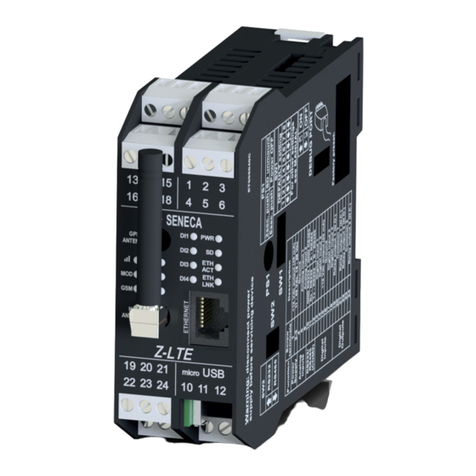
Seneca Z-PC SERIES User manual

ENGLISH 1/8
MI002884-E
EN
EN
EN
EN
Z-PC Line
Z-PC Line
Z-PC Line
Z-PC Line
Z-PC Line
Z-PC Line
Z-PC Line
Z-PC Line
SENECA
S
Z-TWS4
Z-TWS4
Web Multifunction Controller
Straton / Linux
Web Multifunction Controller
Straton / Linux
Installation
Manual
Contents:
- General specifications
- Technical features
- Modbus and CANopen connections
- Installation rules
- Electrical connections
- LEDs signallings
- Default conditions
- Frontal panel
- Accessories
- Decommissioning and disposal.
Installation
Manual
SENECA s.r.l.
Via Austria, 26 – 35127 – PADOVA – ITALY
Tel. +39.049.8705355 - 8705359 - Fax +39.049.8706287
For manuals and configuration software, please see www.seneca.it
This document is property of SENECA srl. Duplication and reproduction are forbidden, if not authorized.
Contents of the present documentation refers to products and technologies described in it. All technical data
contained in the document may be modified without prior notice. Content of this documentation is subject to
periodical revision.

MI002884-E ENGLISH 2/8
General Specifications
CPU ARM 9, S.O. Linux 2.6.28 Kernel
Flash memory: 1 GB
RAM memory: 64 MB
Two Ethernet ports on front panel (internal Hub switch)
One CAN communication port
Three RS485 ports
One RS232 port (as an alternative to an RS485 port)
One USB On The Go port
One USB HOST port
One slot for Micro SD card, max 32 GB
1500 V isolation between power supply and other low voltage circuits
Easy wiring of power supply and serial communication port through Seneca DIN46277
rail bus
2
Removable screw terminals with section of 2.5 mm
Technical Features
Communication ports
RS232 e RS485
Switchable
Maximum Baud rate 115 k
COM 1 (removable 4 pin connector)
RS485
Maximum Baud rate 115 k
COM 2 (screw terminals 1-2-3 or IDC10 connector)
COM 4 (screw terminals 4-5-6)
CAN
CAN bus port
( 10-11-12 or IDC10 connector)screw terminals
Ethernet 1 e Ethernet 2
Fast Ethernet 10/100 Mbps,
Communication port: On frontal from RJ45
Maximum connection length 100 m
USB #1 HOST
Plug-in: USB type A
USB #2 OnTheGo
Plug-in: micro USB
CPU & memory
CPU
ARM 9
Memory
Plug-in for external memory
64 MByte RAM
1 Gbyte FLASH
Micro SD card: max 32 Gbyte

ENGLISH 3/8
MI002884-E
Power supply
Supply voltage
10 – 40 V; 19 – 28 V 50 – 60 Hz
Power consumption
Typical: 4 W , Max: 6 W @ 24V
Environmental conditions
Temperature
-20 – +55°C
Humidity
30 – 90% a 40°C not condensing
Altitude
Up to 2000 m a.s.l.
Storage Temperature
-20 – +85°C
Protection degree
IP20
Connections
Removable 3-way screw terminals, 5 mm pitch
Rear IDC10 connector for DIN 46277 rail
Removable 4 pin connector, two RJ45 connectors, USB and micro USB connectors
Plug-in: micro SD card
Box / Dimensions
Dimensions
L: 100 mm; H: 112 mm; W: 35 mm
Box
PBT, Black
IDC10
RS232
RS485
CAN
Power Supply
IDC10
4 POLI
1, 2, 3
4, 5, 6
ETH
1
RJ45
RJ45
ETH
2
10,11,12
USB #1
USB #2
Standards
The module complies with the following standards:
EN61000-6-4 (electromagnetic emission,
industrial environment).
EN61000-6-2 (electromagnetic immunity,
industrial environment).
EN61010-1 (safety).
Isolation
1500 V
1500V
ADDITIONAL NOTES :
You must install a fuse from at least 1 A, delayed, on the power supply line, near the
module.
500V

MI002884-E ENGLISH 4/8
MODBUS and CANOPEN connection standards
1) Install the module into the DIN rail.
2) Please use a cable with a suitable length to connect the remote modules.
The following table show the cables length.
- Bus Length: Modbus network maximum length as a function of the Baud rate.
This is the length of the cables which connect the two bus terminators modules.
- Derivation Length: Derivation line Maximum length as a function of the Baud Rate
(see Scheme 1).
In order to obtain maximum performances it’s recommended to use a specific shielded
cable, as an example BELDEN 9841.
Scheme 1
Module2
Module1
Module3
Module4
Module5
BUS length
DL= Derivation Length
DL
Terminator Terminator
BUS
Length
Derivation
Length
Baud
rate
M
o
d
b
u
s
1200 m
2 m
115 kbps
C
A
N
2500 m
1000 m
500 m
250 m
100 m
50 m
25 m
150 m
60 m
5 m
5 m
5 m
3 m
0.3 m
20 kbps
50 kbps
125 kbps
250 kbps
500 kbps
800 kbps
1 Mbps
Installation Rules
The module is designed to be installed, in vertical position, on DIN 46277 rail. In order
to ensure optimum performance and a longest working life, the module(s) must be
provided with adequate ventilation and no raceways or other objects that obstruct the
ventilation slots. Never install the modules near heat sources.
We recommend installation in the lower part of the control panel.
Inserting on the DIN rail
As the next picture shows:
1) Insert the module rear IDC10
connector on a DIN rail free slot (there’s
only one way to insert the module
because of polarized connector).
2) Push the two locks placed at the sides
of the rear IDC10 connector to fix the
module.
Z-TWS4
Multi-function
control unit
RJ10
USB #2
USB #1
Z-TWS4
ETH1
ETH2
USB #2
On The Go
RS 485 (COM 4)
123
RS 485 (COM 2)
456
CANopen
101112
Micro SD Card
ARM
Meaning
RS485 signal: B
RS485 signal: GND
RS485 signal: A
RS485 signal: GND
RS485 signal: B
RS485 signal: A
CANopen signal: S-GND
CANopen signal: CAN L
CANopen signal: CAN H
1
3
4
5
6
10
11
12
Screw
terminals
2
RS 232
(COM 0)
ETHERNET 1
ETHERNET 2
Rear bus
connector
(COM 2/CANopen)
USB #1 HOST
Power supply
(from rear bus
connector):
11..40 Vdc
19..28 Vac (50..60 Hz)
Power consumption:
max 6 W
PWR
LINK1
ACT1
LINK2
ACT2
RUN
RX1
TX1
RX2
TX2
RX4
TX4

ENGLISH 5/8
MI002884-E
Rear IDC10 Connector
The picture shows the meaning of the
IDC10 connector pins. Power supply
i s a v a i l a b l e o n l y f r o m r e a r
connector.
CAN/RS485 GND
CAN H / RS485 A
CAN L / RS485 B
Power Supply AC / +
Power Supply AC / -
IDC 10
1
Electrical Connections
Power supply, MODBUS and CAN interface
Power Supply and Modbus interface are available by using the bus for the Seneca
DIN rail, by the rear IDC10 connector or by Z-PC-DINAL1-35 accessory.
Z-PC-DINAL 1-35 Possible Use
If Z-PC-DINAL1-35 accessory is used,
t h e p o w e r s u p p l y s i g n a l s a n d
communication signals may be provided
by the terminals block into the DIN rail
support. The figure shows the meaning
and the position of the terminal blocks.
The DIP-switch that set the 120 Ω
term i n a t o r is us e d onl y for C A N
communication.
G N D S H L D : S h ie l d to prot ect the
connection cables against interference
(recommended).
RS485 COM 2 and RS485 COM 4 Ports
The Z-TWS4 has two serial ports RS 485:
COM 4 e COM 2.
The RS485 COM2 port can be connected
through corresponding screw terminals or
by IDC10 connector.
To select RS 485 on the IDC10 connector,
switch the SW1 to OFF position.
B (-) GND
A (+)
RS 485 (COM 2)
321
RS 485 (COM 4)
654
B (-) GND
A (+)
CAN L
S-GND CAN H
101112
CANopen Port
The Z-TWS4 has a CANopen port available
a t s c r e w t e r m i n a l s 1 0 - 1 1 - 1 2 .
The connection can be performed in
a l t e r n a t i v e o n I D C 1 0 c o n n e c t o r.
To ha v e C A N o p e n po r t on I D C 1 0
connector, switch the SW1 switch to ON
position.

ENGLISH 6/8
MI002884-E
Other Z-TWS4 Ports
USB #1 HOST Port
The Z-TWS4 has a USB HOST type A
connector, t hat can be used as
additional serial port (using a Seneca
S117P1, for example) or to connect an
external USB memory.
USB #1 HOST
321
USB #2 On The Go Port
The Z-TWS4 has a USB On The Go
connector, with micro-USB plug-in, that
can be used as Ethernet connection for
Samba (through a driver before installed
on PC). The MAC ID of this port is
different than the MAC ID of the two
Ethernet ports on the front panel.
USB #2
On The Go
10
11
12
Ethernet RJ45 ports (frontal panel)
The Z-TWS4 has two ethernet ports,
with RJ45 connector, on front panel, for
easy PC connection.
The two ports are internally connected
in HUB/SWITCH modality.
The two ports have the same MAC ID.
RS232 o RS485 COM1 Ports(4 Pin)
The Z-TWS4, through a removable 4
pin connector, has a serial RS232 port
or, as an alternative, has a third RS485
port.
In order to select the RS232 port on the
4 pin removable connector set the SW2
switch to the ON position.
To select this RS485 port on the 4 pin
removable connector set the SW2
switch to OFF position.
The cable length for the RS232
interface must be less than 3 meters.
Ethernet 1 RJ45
Ethernet 2 RJ45
RS485/RS232 COM1

ENGLISH 7/8
MI002884-E
Plug-in Connector for Micro SD Card
SD card
metal
contacts
Micro SD card
The Z-TWS4 has a slot for micro SD
card placed on the side of the case
Before pushing the SD card in this slot,
please be sure that the SD card metal
contacts are facing towards left (Please
see the figure on side).
The serial RS232 4 pin removable connection cable can be assembled as indicated
in the following figure.
(connector code: Phoenix contact: 1778858)
RS232 Cable assembling
LED Signallings
LED
STATE
Meaning of LEDs
PWR Green
On
The module is power on
L1 Red
On
The module is ready for use
LNK1-2 Yellow
On
Ethernet 1-2 connection detected
LNK1-2 Yellow
Off
Ethernet 1-2 connection absent
ACT1-2 Green
Blinking
There is data activity (Ethernet 1-2)
ACT1-2 Green
On
There isn’t data activity (Ethernet 1-2)
RX1-2-4 Red
Blinking
Signaling Data Receiving (COM 1-2-4)
RX1-2-4 Red
On
Verify the connection (COM 1-2-4)
TX1-2-4 Red
Blinking
Signaling Data Transmitting (COM 1-2-4)
TX1-2-4 Red
On
Verify the connection (COM 1-2-4)
RS232 assembling
4 = GND, 3 =RX , 2 = TX, 1 = CTS.
The cable length must be less than
3 meters.
1 2
4
3
3
4 2 1
Phoenix contact
female 4 pin
connector
1778858
Micro SD Card

MI002884-E ENGLISH 8/8
Default Conditions
Module factory settings parameters:
SW1 Switch position
OFF
SW2 Switch position
On
Frontal Panel
Accessories
CODE
DESCRIPTION
Z-PC-DINAL1-35
DIN rail support with screw terminals 1 slot pitch=35 mm
Z-PC-DIN1-35
DIN rail support: 1 slot for rear connector pitch=35 mm
Z-PC-DIN4-35
DIN rail support: 4 slot for rear connector pitch=35 mm
Decommissioning and Disposal
Disposal of Electrical & Electronic Equipment (Applicable throughout the European Union and other European
countries with separate collections programs). This symbol, found on your producr or on its packaging, indicates
that this product should not be treated as household waste when you wish to dispose of it. Instead, it should be
handed over to an applicable collection point for the recycling of electrical & electronic equipment. By ensuring this
product is disposed of correctly, you will help prevent potential negative consequences to the environment and
human health, which could otherwise be caused by inappropriate disposal of this product. The recycling of
materials will help to conserve natural resources. For more detailed information about the recycling of the product,
please contact your local city office, waste disposal service of the retail store where you purchased this product.
10 11
Z-TWS4
12
PWR
LINK1
ACT1
LINK2
ACT2
RUN
COM1
USB #2
USB #1 1 2 3
4 5 6
ETH1
ETH2
RX1
TX1
RX2
TX2
RX4
TX4
DIP-Switch SW1 e SW2
On the module side there are two
switches. With these switches you can
choose between RS232 or RS485 serial
interfaces, from the removable 4 pin
connector, and between CAN BUS or
RS485, from the rear side 10 pin
connector. We suggest to turn off the
module before setting the switches.
SW1
ON CAN BUS
REAR CONNECTOR
OFF RS485 COM2
REAR CONNECTOR
SW2
ON RS232 COM1
REMOVABLE PLUG
OFF RS485 COM1
REMOVABLE PLUG
Other manuals for Z-PC SERIES
5
This manual suits for next models
1
Table of contents
Other Seneca Controllers manuals