Seneca Z-SG User manual

Page 1
MI002633
USER MANUAL
Z-SG / Z-SG-L
Strain gauge converter with
ModbusRTU protocol

USER MANUAL – Z-SG
2
Non è stata trovata alcuna voce d'indice.
Seneca Z-PC Line modules: Z-SG / Z-SG-L
The Z-SG / Z-SG-L modules allows to manage the load cell signals and to process the weight
value.
1. General characteristics
ADC with 24bits resolution
4 wires or 6 wires load cell measure mode
Compression and Traction or only compression load mode
NR 1 analog output configurable in Current or Voltage mode (only Z-SG model)
Load cell sensitivity configurable from +-1mV/V to +-64mV/V or virtually every sensitivity
Measure resolution configurable
RS232 and RS485 port with Modbus RTU protocol
Moving average filtering
Digital input for Tare acquisition (only Z-SG model)
General purpose Digital input (only Z-SG-L model)
Digital output with one configurable weight threshold or “stable measure” condition
Configuration of the module (node) address and baud-rate by Dip-Switches
2. Features
ANALOG
INPUT
Number
1 (for one load cell: + Excitation, - Excitation, +Sense, - Sense, +
Signal, - Signal)
Resolution
24bits
Sampling
frequency
Configurable between: 12.53Hz; 16.65Hz; 24.82Hz; 37.59Hz;
49.95Hz; 50.57Hz; 74.46Hz; 151.71Hz
Rejection
50Hz or 60Hz
Accuracy
Initial: 0.1% of E.E.S.
Linearity: 0.03% of E.E.S.
Thermal stability: 25ppm/K
EMI: < 1%
ANALOG OUT
PUT
(only Z
-
SG model)
Number
1
Accuracy
0.1% of output scale range
Response time (10%
-
90%)
5ms
Voltage
-
type
OUT
Output scale range configurable between: 0..5V or 0..10V by Dip-
Switches. Minimum resistance that can be connected: 2 kΩ
Current
-
type OUT
Output scale range configurable between: 0..20mA or 4..20mA by
Dip-Switches. Max resistance that can be connected: 500 Ω
LOAD CELLS
A load cell or more load cells (if they are parallel-connected) can be connected to the Z-SG
module.
Load impedance
Minimum impedance that can be connected: 87 Ω. This value can
be equivalent impedance of more parallel-connected load cells.
For example: up to 4 load cells (if each cell has input impedance:

USER MANUAL – Z-SG
3
350Ω), up to 8 load cells (if each cell has input impedance: 1000Ω)
Cell sensitivity
Configurable between: ±1mV/V; ±2mV/V; ±4mV/V; ±8mV/V;
±16mV/V; ±32mV/V; ±64mV/V by Dip-Switches. Cell sensitivity can
be acquired by register (in alternative)
Internal
load cell
voltage supply
the #7 screw terminal (+Excitation) powers 5Vdc with reference to
the #10 screw terminal (-Excitation). The #8 screw terminal
(+Sense) reads “+Excitation”, the #11 screw terminal (-Sense)
reads “-Excitation”
CONNECTIONS
RS485 interface
IDC10 connector
RS232 interface
Jack stereo 3.5mm connector: plugs into COMport
PROTECTION
This module provides inputs protection against the ESD (up to 4kV)
for every screw terminals
1500 Vac ISOLATIONS
Between: power supply, ModBUS RS485 and analog output
, analog
input, digital input/output
POWER SUPPLY
Supply voltage
10 – 40 Vdc or 19 – 28 Vac ( 50Hz - 60Hz)
Power
consumption
Max: 2W
The power supply transformer necessary to supply the module must comply with EN60742
(Isolated transformers and safety transformers requirements). To protect the power supply, it is
recommended to install a fuse.

USER MANUAL – Z-SG
4
3. Functioning and connections
Z-SG / Z-SG-L setting parameters are: digital input/output, analog output, operating modality,
load cell sensitivity. These parameters are settable only by Dip-Switches (except load cell
sensitivity, settable by Dip-Switches and by bus communication).
ANALOG INPUT
Input
Screw
terminal
Meaning
+ Excitation 7 Load cell power (+)
+ Sense 8 Reading of load cell power (+)
+ Signal 9 Load cell output signal (+)
- Signal 12 Load cell output signal (-)
- Sense 11 Reading of load cell power (-)
- Excitation 10 Load cell power (-)
To connect the Z-SG / Z-SG-L to load cell in 4-wires modality:
- short-circuit screw terminal 7 to screw terminal 8;

USER MANUAL – Z-SG
5
- short-circuit screw terminal 10 to screw terminal 11.
Use shielded cables for connections.
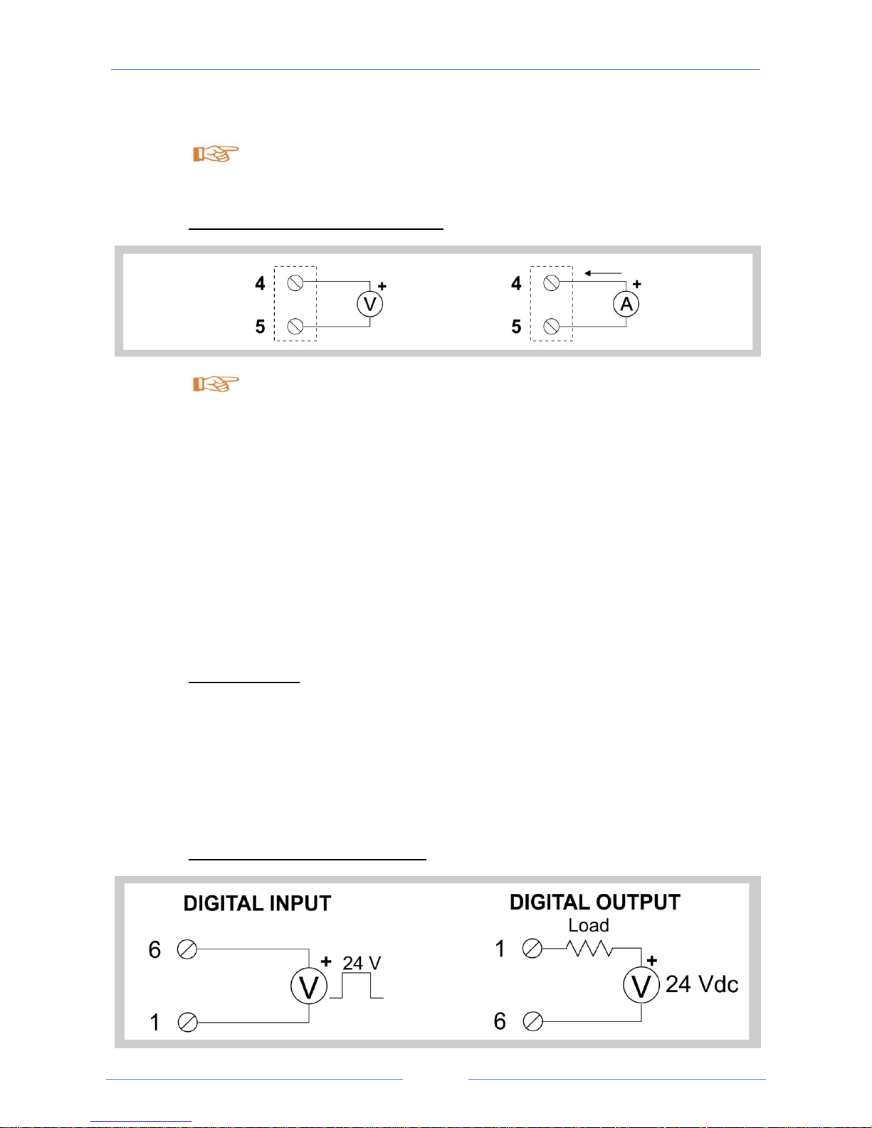
ANALOG OUTPUT (ONLY Z-SG MODEL)
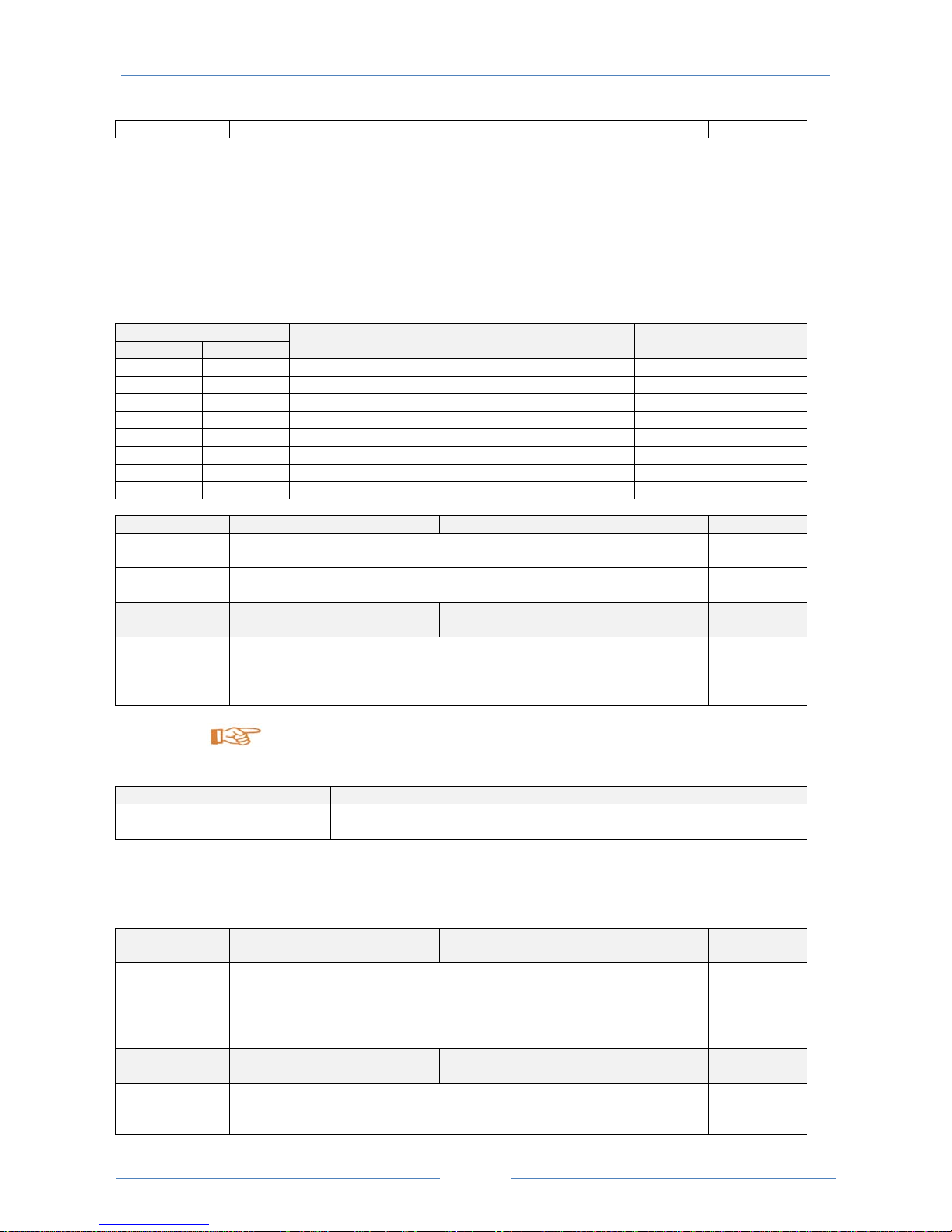
”V” means voltmeter, “A” means amperemeter.
Z-SG module allows to associate net weight to the analog output value (and normalized net-
weight measure), as described in the following points:
- if technical net weight measure (reg.40064, 40065 FP) is less than min tech net-weight
(reg.40050, 40051 FP): normalized net-weight measure (reg.40063) is equal to 0 and analog
output is 0% (0V, 0mA, 4mA), available through screw terminals 4 and 5;
- if technical net weight measure (reg.40064, 40065 FP) is greater than max tech net-weight
(reg.40052, 40053 FP): normalized net-weight measure (reg. 40063) is equal to 30000 and
analog output is 100% (5V, 10V, 20mA), available through screw terminals 4 and 5;
- if technical net weight measure (reg.40064, 40065 FP) is between min tech net-weight and
max tech net-weight, analog output (current/voltage) is directly proportional to the net weight
measure and it is available through screw terminals 4 and 5.
STABLE WEIGHT
Z-SG / Z-SG-L module allows to detect when a weight is stable: weight stability information is
available through bit40066.4 or through digital output.
In particular, a weight measure is stable if the weight variation of net weight (reg.40064, 40065),
in a given time interval (“delta time”, reg.40058), is less than weight interval (“delta weight”,
reg.40056, 40057 floating point).
DIGITAL INPUT OR DIGITAL OUTPUT

USER MANUAL – Z-SG
6
”V” means equivalent voltage generator.
Z-SG module allows to activate a digital input or (in alternative) a digital output only by Dip-
Switch. In the Z-SG model the digital input allows to storage tare value and it can be always
used in alternative to calibration button, in the Z-SG-L model the digital input can be used for
acquire a general purpose input. Digital output allows to open/close a opto-isolated contact: to
use this information, it is possible to connect a 24Vdc voltage generator with a series resistive
load. In this way, if one of the following setting (selected by bit40059.[6:0]) occurs, there is a no
zero current through resistive load (example: lamp).
- gross weight is greater than load cell end scale
- weight is stable and net weight is greater than Threshold
- weight is stable
Dip-switches table
In the following tables: box without circle means Dip-Switch=0 (OFF state); box with
circle means Dip-Switch=1 (ON state).
BAUD
-
RATE (Dip
-
Switches:
SW1
)
1 2 Meaning
Baud-rate=9600 Baud
Baud-rate=19200 Baud
Baud-rate=38400 Baud
Baud-rate=57600 Baud
ADDRESS (Dip
-
Switches:
SW1
)
3 4 5 6 7 8 Meaning
Address and
Baud
-
Rate are acquired from memory(EEPROM)
Address=1
Address=2
Address=3
Address=4
X X X X X X ……………………
Address=63
DIGITAL INPUT/OUTPUT
(Dip
-
Switches:
SW2
)
1 Meaning
Digital input. Calibration button (used during calibration procedure) is enabled
Digital output
ANALOG OUTPUT
(Dip
-
Switches:
SW2
)
2 3 Meaning
Output scale range=0..10V
Output scale range=0..5V
Output scale range=0..20mA
Output scale range=4..20mA
OPERATING MODALITY
(Dip
-
Switches:
SW2
)

USER MANUAL – Z-SG
7
4. RS485 Register table
4 5 Meaning
Factory calibration
Calibration with known weight
Factory calibration using calibration button (or digital input)
Calibration with known weight using calibration button (or digital input)
LOAD CELL
SENSITIVITY
(Dip
-
Switches:
SW2
)
6 7 8 Meaning
±1 mV/V
±2 mV/V
±4 mV/V
± 8mV/V
±16 mV/V
±32 mV/V
±64 mV/V
The module acquires load cell sensitivity from register 40044, 40045 (FP): in this case,
real numbers for sensitivity are allowed
RS485 TERMINATOR (Dip
-
Switches:
SW3
)
1 2 Meaning
RS485 terminator disabled
RS485 terminator enabled
Generic parameters of Z-SG/Z-SG-L module are shown in the following table.
Name
Range
Interpretation of
register
R/W
Default
Address
MachineID / MSB, LSB R 40001
Id_Code (Module ID) 0x17 (23
decimal)
Bit [15:8]
Ext_Rev (Module version) Bit [7:0]
FWREV / Word R 40002
Firmware Code
ADC
POLARITY
/ Word R/W 40003
ADC POLARITY: if it is 0, the ADC is bipolar; if it is 1, is
unipolar
Status / Bit R/W 40066
These bits aren’t used 0 Bit [15:7]
Z-SG-L MODEL: 0= digital input is low, 1= digital input is
high
Z-SG MODEL: not used
0 Bit 6
Not used 0 Bit 5
Weight stability. 0=weight is not stable; 1=weight is stable 0 Bit 4
Tare-value storage in RAM memory. 0=no operation;
1=save the tare value
0 Bit 3
0=gross weight is greater than tare-value saved in 0 Bit 2

USER MANUAL – Z-SG
8
memory;
1=gross weight is less than tare-value saved in memory
0=gross weight is less than load cell end scale;
1=gross weight is greater than load cell end scale
0 Bit 1
0=net weight is less than Threshold (reg.40054, 40055
FP) or weight measure is not stable
1=net weight is greater than Threshold (reg.40054, 40055
FP) and weight measure is stable
0 Bit 0
Command / Bit R/W 40068
Reset of module, if reg.40068=0xABAC=43948;
save value-tare in RAM memory,
if reg.40068=0xC1BA=49594 (equivalent command to
bit40066.1=1);
save standard weight in EEPROM memory,
if reg.40068=0xC60C=50700
save value-tare in EEPROM and RAM memory,
if reg.40068=0xC2FA=49914
0
Dip-Switch
Status
/ Bit R 40067
Switch1 of “SW1” state. Bit40067.15=0 corresponds to
Switch1=”0”, bit40067.15=1 corresponds to Switch1=”1”
/ Bit 15
Switch2 of “SW1” state. Bit40067.14=0 corresponds to
Switch2=”0”, bit40067.14=1 corresponds to Switch2=”1”
/ Bit 14
Switch3 of “SW1” state. Bit40067.13=0 corresponds to
Switch3=”0”, bit40067.13=1 corresponds to Switch3=”1”
/ Bit 13
Switch4 of “SW1” state. Bit40067.12=0 corresponds to
Switch4=”0”, bit40067.12=1 corresponds to Switch4=”1”
/ Bit 12
Switch5 of “SW1” state. Bit40067.11=0 corresponds to
Switch5=”0”, bit40067.11=1 corresponds to Switch5=”1”
/ Bit 11
Switch6 of “SW1” state. Bit40067.10=0 corresponds to
Switch6=”0”, bit40067.10=1 corresponds to Switch6=”1”
/ Bit 10
Switch7 of “SW1” state. Bit40067.9=0 corresponds to
Switch7=”0”, bit40067.9=1 corresponds to Switch7=”1”
/ Bit 9
Switch8 of “SW1” state. Bit40067.8=0 corresponds to
Switch8=”0”, bit40067.8=1 corresponds to Switch8=”1”
/ Bit 8
Switch1 of “SW2” state. Bit40067.7=0 corresponds to
Switch1=”0”, bit40067.7=1 corresponds to Switch1=”1”
/ Bit 7
Switch2 of “SW2” state. Bit40067.6=0 corresponds to
Switch2=”0”, bit40067.6=1 corresponds to Switch2=”1”
/ Bit 6
Switch3 of “SW2” state. Bit40067.5=0 corresponds to
Switch3=”0”, bit40067.5=1 corresponds to Switch3=”1”
/ Bit 5
Switch4 of “SW2” state. Bit40067.4=0 corresponds to
Switch4=”0”, bit40067.4=1 corresponds to Switch4=”1”
/ Bit 4
Switch5 of “SW2” state. Bit40067.3=0 corresponds to
Switch5=”0”, bit40067.3=1 corresponds to Switch5=”1”
/ Bit 3
Switch6 of “SW2” state. Bit40067.2=0 corresponds to
Switch6=”0”, bit40067.2=1 corresponds to Switch6=”1”
/ Bit 2
Switch7 of “SW2” state. Bit40067.1=0 corresponds to
Switch7=”0”, bit40067.1=1 corresponds to Switch7=”1”
/ Bit 1
Switch8 of “SW2” state. Bit40067.0=0 corresponds to
Switch8=”0”, bit40067.0=1 corresponds to Switch8=”1”
/ Bit 0
Sampling Freq
Rejection
/ Word R/W 40060
The value of reg.40060 relates to one of the configuration
shown in the following table, for sampling frequency, 50Hz
rejection and 60Hz rejection. As you can see, only a few
0x0052

USER MANUAL – Z-SG
9
register (40060) values are allowed
Register (40060) value Sampling frequency
(Hz)
50Hz rejection 60Hz rejection
0x decimal
001B 27 151.71 NO NO
0037 55 74.46 NO NO
0052 82 49.95 YES YES
006D 109 37.59 NO YES
009B 155 50.57 NO NO
00B7 183 24.82 YES NO
00D2 210 16.65 YES YES
00ED 237 12.53 NO YES
Resolution / Bit R/W 40059
0=resolution value is acquired from bit[14:8]; 1=resolution
is equal to 24bits
0 Bit 15
Resolution value (needs to be multiplied by 1000), if
bit40059.15=0
30 Bit [14:8]
Number Of
Samples
Between: 1; 100 Word R/W 40061
These bits aren’t used / Bit [15:8]
Number of samples to execute the moving average of
weight. Registers 40064 and 40065 contain the result of
moving average (floating point weight)
100 Bit [7:0]
To choose the number of samples, see the following table.
Number of samples Weight measure stability Weight measure speed
High values (up to 100) Better Worst
Low values (up to 1) Worst Better
Address
Parity
/ MSB, LSB R/W 40004
Address for RS485 (address of module/node if parameters
are configurated by memory modality): from 0x01=1 to
0xFF=255
1 Bit [15:8]
Parity for RS485: 0=there isn’t; 1=even parity; 2=odd
parity
0 Bit [7:0]
Baudrate
Delay
/ MSB, LSB R/W 40005
Baud-rate for RS485 (baud-rate of module/node if
parameters are configurated by memory modality):
0=4800; 1=9600; 2=19200; 3=38400; 4=57600;
38400 Bit [15:8]

USER MANUAL – Z-SG
10
5=115200; 6=1200; 7=2400
Delay for RS485 (delay of communication response: it
represents the number of the pauses(*) between the end
of Rx message and the start of Tx message): from 0x00=0
to 0xFF=255
(*)1 pause=6 characters
0 Bit [7:0]
Load-cell configuration parameters are shown in the following table.
Sensitivity
MSW
FP32bit_MSW R/W
40044
Sensitivity
LSW
FP32bit_LSW R/W
40045
If Dip-Switches SW2-7 is “ON”, SW2-8 is “ON”, SW2-9 is
“ON”, the module acquires sensitivity [mV/V] from these
registers (reg.40044, 40045 FP)
2[mV/V]
Load cell end
scale MSW
FP32bit_MSW R/W
40046
Load cell end
scale LSW
FP32bit_LSW R/W
40047
If load cell end scale is known, switch Dip-Switches SW2-4
to OFF and SW2-5 to OFF. In this case, reg. 40046,
40047 (FP) is the load cell end scale [mg, g, kg, etc…]
10000
[mg, g,
kg, etc…]
Known weight
MSW
FP32bit_MSW R/W
40048
Known weight
LSW
FP32bit_LSW R/W
40049
If load cell end scale is unknown, switch Dip-Switches
SW2-4 to OFF and SW2-5 to ON. In this case, reg. 40048,
40049 (FP) is the known weight [mg, g, kg, etc…]
10000
[mg, g,
kg, etc…]
Net-weight parameters are shown in the following table.
Tech net-
weight
measure MSW
FP32bit_MSW R 40064
Tech net-
weight
measure LSW
FP32bit_LSW R 40065
Technical net weight measure [mg, g, kg, etc…]
/
Norm net-
weight
measure
Depending on the ADC
polarity
Word R 40063
Normalized net weight measure.
If bipolar, the value is from –30000 to +30000
If unipolar, the value is from 0 to +60000
(see the ADC polarity)
/
Min tech net-
weight MSW
FP32bit_MSW R/W 40052
Min tech net-
weight LSW
FP32bit_LSW R/W 40053
Min technical net weight. It corresponds to the analog
output start scale (settable by Dip-Switches: 0V, 0mA,
0 [mg, g,
kg, etc…]

USER MANUAL – Z-SG
11
4mA)
Max tech net-
weight MSW
FP32bit_MSW R/W 40050
Max tech net-
weight LSW
FP32bit_LSW R/W 40051
Max technical net weight. It corresponds to the analog
output end scale (settable by Dip-Switches: 5V, 10V,
20mA)
10000
[mg, g,
kg, etc…]
ADC value is shown in the following table.
ADC value Word R 40062
ADC value (it refers to gross weight)
Stable-weight parameters are shown in the following table.
Delta weight
MSW
FP32bit_MSW R/W 40056
Delta weight
LSW
FP32bit_LSW R/W 40057
Weight interval [mg, g, kg, etc…] to define if a weight
measure is stable, with reference to the net weight
1 [mg, g,
kg, etc…]
Delta time Word R/W 40058
Time interval to define if a weight measure is stable, with
reference to the net weight
1 (=100
[msec])
A weight measure is stable if the weight variation of net weight (reg.40064,
40065), in a given time interval (“delta time”, reg.40058), is less than weight interval (“delta
weight”, reg.40056, 40057 floating point); time interval (“delta time”) and weight interval
(“delta weight”) are settable by “stable weight condition” window.
Digital output parameters are shown in the following table.
Digital output Bit R/W 40059
Digital output behavior if the selected condition of digital
output occurs (see bit[6:0]).
0=if the selected condition of digital output occurs, digital
output (open normally) switches from open to closed (no-
zero current through external load)
1=if the selected condition of digital output occurs, digital
output (closed normally) switches from closed to open (no
current through external load)
0 Bit 7
Condition of digital output. It is possible to select one of
the following setting:
0=gross weight is greater than load cell end scale
1=weight is stable and net weight is greater than
Threshold
2=weight is stable
0 Bit [6:0]
Threshold
MSW
FP32bit_MSW R/W 40054
Threshold FP32bit_LSW R/W 40055

USER MANUAL – Z-SG
12
5. Z-SG / Z-SG-L tarature using Modbus registers
There are two alternative modalities to configure the module using the Modbus registers:
CALIBRATION WITH KNOWN WEIGHT
WARNING
Gross weight (tare + known weight) must not to exceed load cell end scale, to avoid
serious damage to the cell.
1) Power off the module before configuring it by Dip-Switches to avoid serious damage
due to electrostatic discharges.
2) Switch Dip-Switch SW2-1 as desired: “OFF”=digital input enabled, digital output disabled;
“ON”=digital input disabled, digital output enabled
3) Switch Dip-Switches SW2-2 and SW2-3 as desired: see Dip-Switches table
4) Switch Dip-Switches SW2-4 to “OFF” and SW2-5 to “ON”
5) Switch Dip-Switches SW2-6 to “ON”, SW2-7 to “ON”, SW2-8 to “ON”
6) Power on the module
7) Write sensitivity value in reg. 40044, 40045 (FP)
8) Write known weight value in reg. 40048, 40049 (FP)
9) Reset the module (write 0xABAC=43948 in reg.40068)
New sensitivity and known weight are saved in Z-SG/Z-SG-L module.
10) Put the tare on the balance
11) Save the tare value in EEPROM memory (write 0xC2FA=49914 in reg.40068)
12) Put the known weight on the tare
LSW
Threshold of net weight (see bit40059.[6:0]) 0

USER MANUAL – Z-SG
13
13) Save the known weight in EEPROM memory (write 0xC60C=50700 in reg.40068)
FACTORY CALIBRATION
1) Power off the module before configuring it by Dip-Switches to avoid serious damage
due to electrostatic discharges.
2) Switch Dip-Switch SW2-1 as desired: “OFF”=digital input enabled, digital output disabled;
“ON”=digital input disabled, digital output enabled
3) Switch Dip-Switches SW2-2 and SW2-3 as desired: see Dip-Switches table
4) Switch Dip-Switches SW2-4 to “OFF” and SW2-5 to “OFF”
5) Switch Dip-Switches SW2-6 to “ON”, SW2-7 to “ON”, SW2-8 to “ON”
6) Power on the module
7) Write sensitivity value in reg. 40044, 40045 (FP)
8) Write load cell end scale in reg. 40046, 40047 (FP)
New sensitivity and load cell end scale are saved in Z-SG / Z-SG-L module.
10) Put the tare on the balance
11) Save the tare value in EEPROM memory (write 0xC2FA=49914 in reg.40068

USER MANUAL – Z-SG
14
6. Setting by calibration button
There are two alternative modalities to configure the Z-SG / Z-SG-L module by calibration
button (if the user has not a Personal Computer and has a known weight that corresponds to
the analog output end scale).
CALIBRATION WITH KNOWN WEIGHT USING CALIBRATION BUTTON (DIGITAL INPUT
CAN ALSO BE USED FOR Z-SG MODEL)
WARNING
Gross weight (tare + known weight) must not to exceed load cell end scale, to avoid
serious damage to the cell.
1) Power off the module before configuring it by Dip-Switches to avoid serious damage
due to electrostatic discharges.
2) Switch the Dip-Switches SW2-4 to “ON” and SW2-5 to “ON”. In this way, setting by
calibration button is possible.
3) Switch the Dip-Switch SW2-1 to “OFF”. In this way, calibration with known weight using
calibration button (or digital input) is possible.
4) Switch the Dip-Switches SW2-2 and SW2-3 as shown in Dip-Switches table, to select one of
the possible modalities of analog output.
5) Switch the Dip-Switches SW2-6, SW2-7, SW2-8 to choose the load cell sensitivity (see Dip-
Switch table)
6) Power on the module
7) Keep pushed the calibration button (or in alternative use digital input signal) until LED ERR is
“ON”
8) Release the calibration button
9) Control that the LED ERR is flashing
10) Put the tare on the load cell

USER MANUAL – Z-SG
15
11) Keep pushed the calibration button (or in alternative use digital input signal for Z-SG model)
until LED ERR switches from flashing to “OFF”
The module has acquired the tare value.
12) Keep pushed the calibration button (or in alternative use digital input signal) until LED ERR
is “ON”
13) Release the calibration button
14) Control that the LED ERR is flashing
15) Put the known weight on the tare
16) Keep pushed the calibration button (or in alternative use digital input signal) until LED ERR
switches from flashing to “OFF”
The module has acquired the known weight value.
17) Power off the module
18) Switch the Dip-Switches SW2-4 to “OFF” and SW2-5 to “ON”. In this way, the module is
calibrated.
19) Power on the module
When calibration procedure is ended, it is possible to calibrate by the digital input (only
Z-SG model) or by calibration button (after switching SW2-1 to “OFF”: digital input is enabled). If
a digital signal commutation (from “0” to “1”) occurs (through screw terminals 1-6), a tare value
is saved in RAM memory. This value is erased if the module is power off or when a new digital
signal commutation (from “0” to “1”) occurs (through screw terminals 1-6).
If the module is power off during this procedure, calibration setting is lost. Restart the
calibration procedure from the first point.
7. FACTORY CALIBRATION USING CALIBRATION
BUTTON
WARNING
Gross weight (tare + known weight) must not to exceed load cell end scale, to avoid
serious damage to the cell.

USER MANUAL – Z-SG
16
1) Power off the module before configuring it by Dip-Switches to avoid serious damage
due to electrostatic discharges.
2) Switch the Dip-Switches SW2-4 to “ON” and SW2-5 to “OFF”. In this way, factory calibration
using calibration button (or digital input). It is possible to acquire tare value by digital input or
calibration button.
3) Switch the Dip-Switch SW2-1 to “OFF”. In this way, calibration button for digital input (used
during calibration procedure) is enabled and it is possible to acquire tare value.
4) Switch the Dip-Switches SW2-2 and SW2-3 as shown in Dip-Switches table, to select one of
the possible modalities of analog output.
5) Switch the Dip-Switches SW2-6, SW2-7, SW2-8 to choose the load cell sensitivity (see Dip-
Switch table)
6) Power on the module
7) Put the tare on the load cell
8) Keep pushed the calibration button (or in alternative use digital input signal) until LED ERR is
“ON”
The Z-SG / Z-SG-L module has acquired tare value: this value is saved in EEPROM
(keep saved when the module is power off).
9) Power off the module
10) Switch the Dip-Switches SW2-4 to “OFF” and SW2-5 to “OFF”. In this way, Z-SG / Z-SG-L
module is calibrated.
11) Power on the module
When calibration procedure is ended, it is possible to calibrate the module by the
digital input (only Z-SG model) or by calibration button (after switching SW2-1 to “OFF”: digital
input is enabled). If a digital signal commutation (from “0” to “1”) occurs (through screw
terminals 1-6), a tare value is saved in RAM memory. This value is erased if the module is
power off or when a new digital signal commutation (from “0” to “1”) occurs (through screw
terminals 1-6).
If the module is power off during this procedure, calibration setting is lost. Restart the
calibration procedure from the first point.
Analog output end scale is related to load cell end scale, with the following equation:
Real end scale = Load cell end scale – tare
Example:
If load cell end scale is equal to 50kg, tare is equal to 10kg and analog output scale range is
0..10V, real end scale is
Real end scale = 50 – 10 = 40kg

USER MANUAL – Z-SG
17
If technical net weight is equal to real end scale, analog output will result
50kg 10kg
50kg X 100=80%
and 80% corresponds to an analog output equal to 8V.
8. Remote Memorizing of the Tare
The memorizing of the tare may be perfomed in the following ways:
9. LEDs for signalling
In the front-side panel there are 4 LEDs and their state refers to important operating conditions
of the module.
LED
LED status
Meaning
PWR Constant light The power is on
ERR Blinking light See “Setting by calibration button”
Turn off after 3
seconds
See “Setting by calibration button”
RX Constant light Verify if the bus connection is corrected
Blinking light The module received a data packet

USER MANUAL – Z-SG
18
TX Blinking light The module sent a data packet
10. Easy-SETUP
To configure the Seneca Z-PC Line modules, it is possible to use Easy-SETUP software,
Free-downloadable from the www.seneca.it; the configuration can be performed by RS232 or
RS485 bus communication.
Other manuals for Z-SG
3
This manual suits for next models
1
Table of contents
Other Seneca Media Converter manuals

Seneca
Seneca Z109UI2 User manual

Seneca
Seneca Z-SG User manual

Seneca
Seneca ZC-SG User manual

Seneca
Seneca Z-SG3 User manual

Seneca
Seneca Z201-H User manual

Seneca
Seneca K109S User manual

Seneca
Seneca Z Series User manual

Seneca
Seneca Z204-1 User manual

Seneca
Seneca S117P1 User manual

Seneca
Seneca R-KEY-MBUS User manual

Seneca
Seneca K109UI User manual

Seneca
Seneca Z-SG2-L User manual

Seneca
Seneca Z107 User manual

Seneca
Seneca Z109REG-BP User manual

Seneca
Seneca Z109TC2-1 User manual

Seneca
Seneca Z Series User manual

Seneca
Seneca Z201 User manual

Seneca
Seneca Z-8TC-SI User manual

Seneca
Seneca Z-4RTD2 User manual

Seneca
Seneca EASY-USB User manual