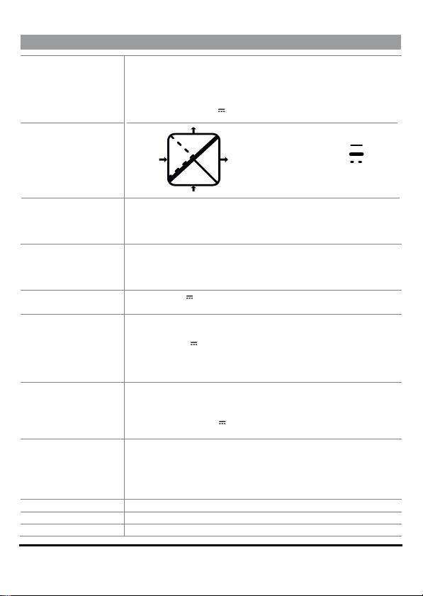
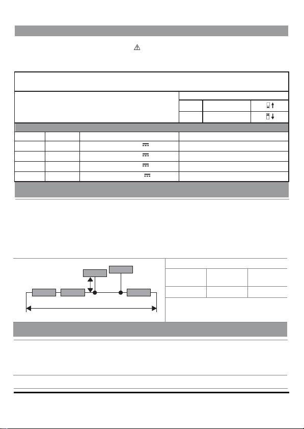
Seneca Z204-1 User manual

ENGLISH - 1/8
MI003615-E
This document is the property of SENECA srl. Copies and reproduction are prohibited unless authorised. The
content of this document corresponds to the d
escribed products and technologies. Stated data may be modified
or supplemented for technical and/or sales purposes.
INSTALLATION MANUAL
Z204-1
True RMS AC/ DCconverter with Modbus protocol onRS485
SENECA s.r.l.
Via Austria, 26 – 35127 – PADOVA – ITALY
Tel. +39.049.8705355 - 8705359 - Fax +39.049.8706287
For manuals inFrench, German, English and configuration software, visit the
www.seneca.it/products/204-1 website
EN
THE ORIGINAL VERSION IS IN ITALIAN LANGUAGE

ENGLISH - 2/8
TECHNICAL SPECIFICATIONS
STANDARDS
EN61000-6-4 electromagnetic emissions, industrial environment
EN61000-6-2. Electromagnetic immunity, industrial environment.
EN61010-1 (safety)
Install a fuse with a maximum capacity of 2.5 A near the module
For voltages over 1000 V , install a 4kV overvoltage protection device
INSULATION Protection
impedance
N.B: use in environments with pollution degree 2 or lower.
ENVIRONMENTAL
CONDITIONS
Temperature: -20 – + 65°C
Humidity/Altitude: 30 -90% non condensing, up to 2000 m above sea level.
Storage temperature: -20 – + 85°C
Protection rating: IP20
CONNECTIONS
Removable 4-way screw terminals, 3.5 mm pitch for cable up to 2.5
mm2, rear IDC10, for 35 mm DIN bar IEC EN60715
3.5 mm front jack for configuration
4 mm standard bushes
POWER SUPPLY
Voltage 10..40 V or 19..28 V
~
50 – 60 Hz
Typical absorption 1 W
INPUTS
Voltage: 0/850 V
~
Input impedance 4 MΩ (precision: 0.5%).
Frequency 30 - 60 Hz,
Voltage: 0/1200 V , Input impedance 4 MΩ (precision: 0.5%).
Pass-band: 30-400 Hz (-3 dB).
N.B.: the instrument below 3% of the selected full scale does not give the
correct measurement
OVERVOLTAGE
Category V: up to 300 Vac/dc:
Category III: up to 600 Vac/dc;
Category II: up to 1000 Vac/dc;
For voltages up to 1200 V provide an overvoltage limiter external to the 4
kV device.
OUTPUTS
Current: 0/4..20 mA, max resistance 500 Ω (precision: 0.1%)
Continuous voltage: 0
-10 V selectable via the software. Minimum load
resistance: 1 kΩ. (precision: 0.1%)
Temperature drift: 100 ppm/K
Response time for a stepped variation: 1 s from 10 to 90%
CONFIGURABILITY
Baud rate and MODBUS Address via DIP-switch or via software.
Dimensions (LxHxD)
35 x 102.5 x 111 mm (terminals included).
Case
PA6 material, black.
t
Power
Supply
4000 V~
1500 V~
10..40 Vdc / 19..28 Vac
0..1200 Vdc
0..850 Vad Input
Configuration
port
Output
RS232
RS485
mA / V

ENGLISH - 3/8
PRELIMINARY WARNINGS
MODULE LAYOUT
35 mm 111 mm
102.5 mm IDC10: CAN/MODBUS and power supply
Dimensions: 35 x 102.5 x 111mm, Weight:: 170 g, Container PA6, black
The word WARNING preceded by the symbol indicates conditions or actions that put the
user's safety at risk. The word CAUTION preceded by the symbol indicates conditions
or actions that might damage the instrument or the connected equipment.
The warranty shall become null and void in the event of improper use or tampering with the device or
accessories supplied by the manufacturer as necessary for its correct operation, and if the instructions
contained in this manual are not followed.
WARNING: The full content of this manual must be read before operation. The module
must only be used by qualified electricians.
Specific documentation is available from www.seneca.it/prodotti/ Z204-1.
The module must be repaired and damaged parts replaced by the Manufacturer. The product
is sensitive to electrostatic discharges. Take appropriate measures during any operation.
Important: Obstructing ventilation slots with any object is prohibited.
Installing the module next to devices that generate heat is prohibited.
Electrical and electronic waste disposal (applicable in the European Union and other countries
with selective waste collection). The symbol on the product or its packaging shows that the
product must be disposed of at a collection centre authorised to recycle electrical
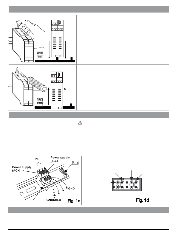
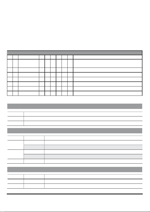
and
electronic waste.
ASSEMBLY STANDARDS
The module has been designed for vertical installation on an IEC EN 60715 omega guide. For optimal
operation and long life, adequate ventilation must be provided. Avoid positioning channels or other objects
that obstruct the ventilation slots. Avoid mounting modules over equipment generating heat. Installation in
the bottom part of the switchboard is recommended.
t
t

ENGLISH - 4/8
INSTALLATION ON AND REMOVAL FROM THE IEC EN 60715 RAIL
Fig. 1a 19 20 21
Insertion onto the OMEGA IEC EN 60715 rail:
1) Move the two hooks on the back of the module outward
as illustrated in Fig. 1b.
22 23 24 10 11 12
2) Insert the rear IDC10 connector of the module into a free
slot of the OMEGA rail accessory as shown in Fig. 1a.
(insertion is univocal as connectors are polarised).
9 10 11 12
1314 1516
3) To secure the module to the OMEGA guide, tighten the
two hooks on the side of the IDC10 rear connector as
illustrated in Fig. 1a.
1718 1920
2122 2324
Fig. 1b
19 20 21
22 23 24 10 11 12
Removal from the OMEGA IEC EN 60715 rail:
As shown in figure 1b:
1 2 3 4 9
10 11 12
5 6 7 8
1314 1516
1) With the help of a screwdriver, pull the two hooks on the
side of the module outwards.
1718 1920
2526 2728
2122 2324
2930 3132
2) Slowly extract the module from the rail.
USE OF THE Z-PC-DINAL ACCESSORY
CAUTION
Do not turn the module upside down and do not force the insertion of the IDC10 connector on
the Z-PC-DIN bus. The module's rear IDC10 connector must be plugged into a free slot on the Z-
PC-DIN bus.
The illustration shows the meanings of the various IDC10 connector pins if signals are to be sent via
them directly.
Fig. 1 c and Fig. 1 d show the power connection and RS485 port on the IDC10.
Power supply AC+
GND / RS485 GND
Power supply AC-
RS485 A
1
RS485 B
L/ B
H / A
IDC10
Z-PC-DINAL
SUPPLY AND MODBUS INTERFACE
Supply and MODBUS interface are available via the Seneca BUS.
Access to the Seneca BUS is available via the IDC10 connector, or via the Z-PC-DINAL-35 accessory.
t

ENGLISH - 5/8
WARNING
Use the RS232 serial port only after disconnecting the high voltage input.
This communication port can only be used to program the module. Z-
NET or Easy Setup are our
configuration software. The RS 232 serial port uses the following communication parameters:
2400,8,N,1.
During the use of the RS232 port, the bus will be inactive;
it will reactivate automatically a few seconds
after the last message exchanged on the COM port. The DB9 connection cable 3.5 mm stereo jack can
be assembled as shown in the figure below or purchased as an accessory (code PM001601).
ELECTRICAL CONNECTIONS
WARNING
BEFORE CARRYING OUT ANY INSTRUMENT CONNECTIONS, MAKE SURE THAT YOU DISCONNECT ALL THE
CIRCUITS SUBJECT TO A DANGEROUS VOLTAGE. TO CONNECT THE HIGH VOLTAGE INPUT USE ONLY THE
PLUGS SUPPLIED WITH THE INSTRUMENT
Insertion of high voltage plugs
The figure at the side shows the insertion points of the
two 4mm banana plugs supplied with the instrument.
Polarity of the high voltage connection
In the case of DC measurement, the polarity
is indifferent.
Rs485 PORT COM Sw3 = ON
4 A (+)
5 B (-)
6 GND
RS232
DB9-F GND Tx Rx
GND
Tx
6 1 Rx
9 5
3.5 mm stereo jack
Connection for RS485 communication using the MODBUS master
system as an alternative to the Z-PC-DINx bus.
N.B. the indication of the RS485 connection polarity is not
standardised and in some devices may be inverted.
t

ENGLISH - 6/8
DIP - SWITCH SETTINGS
WARNING
BEFORE YOU ATTEMPT USING THE DIP-SWITCHES, MAKE SURE THAT YOU HAVE
DISCONNECTED ALL DANGEROUS VOLTAGE CIRCUITS.
The range of the instrument is established by the SW1 DIP-switch settings (2-way); the table
below shows the useful combinations for the pre-set ranges.
In the following tables l corresponds to DIP- switch = 1
(ON) no indication corresponds to DIP- switch = 0 (OFF)
DIP Switch
ON
OFF
DIP-Switch SW1 - INPUT SCALES (maximum limit values)
7
8
DC SCALE
AC SCALE
0 – 150 V
0 – 100 V~
0 – 500 V
0 – 350 V~
0 – 850 V
0 – 600 V~
0 – 1200 V
0 – 850 V~
MODBUS CONNECTION RULES
1)
Install the modules in the omega rail (120 max)
2)
Connect the remote modules using cables of an appropriate length.
3)
The following table shows cable length data:
- Bus length: maximum length of the Modbus network in function of the Baud Rate.
It is the length of the cables that connect the two modules on which the bus terminal
has been inserted by means of a DIPSwitch (see Diagram 1).
- Derivation length: maximum length of a derivation (see Diagram 1).
Diagram 1
Module 3
DL
Module 1 Module 2 Module 5
DL: Derivation length
Bus length
•
MODBUS Diagram 1
BUS length
Derivation
length
Baudrate
1200 m 2 m 115kbps
For maximum performance, it is
recommended to use special shielded
cables, such as BELDEN 9841.
PROGRAMMING VIA MODBUS INTERFACE
The module can be programmed/configured via the MODBUS interface. For
details on communication, refer to the User Manual.
For the variation of the parameters, the communication software is available in the download area of
the www.seneca.it website: Z-NET and EASY-SETUP.
With all DIP-switches in the OFF position (the communication parameters are taken from the memory).
t
Module 4

ENGLISH - 7/8
To obtain the best resolution, select through the SW1 Dip-Switch group the input scale (among the
four in the previous table) whose full scale is closer to and higher than the value to be measured.
After selecting the measurement range, it is necessary to configure via software the desired start and full
scale within the selected range and then the current or voltage values that you want to retransmit as the
measurement start and full scale.
For example: if the value to be measured is 680 V ~, then set Dip-switches SW1-1 =
0 and SW1-2 = 1 (this corresponds to the 0-850 V ~ measuring range).
Using the Easy Setup software we can configure the voltage output 0 V for the start of the scale and 10V
for the full scale so we will read 8V at the output.
DIP-Switch SW2 - COMMUNICATION PARAMETERS
1
2
BAUD RATE
3
4
5
6
7
8
COMMUNICATION ADDRESS
From
software
Communication parameters from EEPROM(*)
9600 Baud
Fixed address 01
19200 Baud
Fixed address 02
38400 Baud
Fixed address 03
57600 Baud
Fixed address 04
X
X
X
X
X
X
Fixed address, represented as binary
Fixed address 63
(*) Note: if DIP-switches from 1 to 8 are OFF, the communication parameters are loaded from EEprom.
Sw3 - MEASUREMENT AVAILABLE ON TERMINALS 4 5 6
1
Measurement available on terminals 4 5 6
Analogue output: retransmitted current or voltage
RS485 serial port
LED SIGNALS ON THE FRONT PANEL
LED
Status
LED meaning
PWR
On
Power supply on
Flashing
Internal error or out of scale
RX
On
Check the connection
Flashing
Receipt of packet completed
TX
Flashing
Transmission of packet completed
BASE MODBUS REGISTERS (Holding register)
Address
Name
Description
40047
VRMS (MSB)
Input voltage value (floating point, most significant bits)
40048
VRMS(LSB)
Input voltage value (floating point, least significant bits)
t

ENGLISH - 8/8
SUPPLY AND MODBUS INTERFACE
Electrical power connections are available from both terminals and using the Seneca
DIN guide bus. Connections relative to the MODBUS RS485 interface are instead
available using the DIN rail bus or, after configuring the SW3 DIP-switch to ON,
through terminals 4, 5 and 6.
POWER SUPPLY
19 – 28 V~
1 50 – 60 Hz
2 10 – 40 V
1 W Max
The power voltage must be between 10 and 40 V (any
polarity), or between 19 and 28 V~. The upper limits must not
be exceeded in order to avoid serious risk to the module.
The
power supply source must be protected from any module
malfunctions using appropriately-sized safety fuses.
TRUE RMS VOLTAGE INPUT
+IN A
IN B
Max 1200 Vdc Max 850 Vac
WARNING REFERRED TO GROUND
Current output
Voltage output
5
4
SW3= OFF
4– 20 mA
The output settings
can be modified by
the software.
5
6
SW3= OFF
0 – 10 V
The output settings
can be modified by
the software.
FACTORY SETTINGS
Default conditions for module configuration parameters:
Full scale
1000 V
Analogue output
Current 4 - 20 mA
Communication parameters
38400 8, N, 1 Addr. 1
To change the input scale, set Dip-Switches SW1 as shown in the relevant table and load the configuration
via the configuration software (EasySetup or Z-NET =
ACCESSORIES
Code
Description
Z-PC-DINAL1-35
DIN rail support with power supply terminals P = 35 mm
Z-PC-DIN1-35
DIN 1-slot support for rear connector P = 35mm
CS-JACK-DB9F
PC-Z204-1 serial cable
CONTACT INFORMATION:
Technical support supporto@seneca.it Product information commerciale@seneca.it
t
+
+
Table of contents
Other Seneca Media Converter manuals

Seneca
Seneca R-KEY-MBUS User manual

Seneca
Seneca Z-SG User manual

Seneca
Seneca K109S User manual

Seneca
Seneca K109UI User manual

Seneca
Seneca Z-SG User manual

Seneca
Seneca Z109REG-BP User manual

Seneca
Seneca S117P1 User manual

Seneca
Seneca Z-SG2 User manual

Seneca
Seneca Z109REG-BP User manual

Seneca
Seneca Z Series User manual

Seneca
Seneca Z-SG User manual

Seneca
Seneca Z-4RTD2-SI User manual

Seneca
Seneca Z111 User manual

Seneca
Seneca S107USB User manual

Seneca
Seneca Z109UI2 User manual

Seneca
Seneca Z-8TC-SI User manual

Seneca
Seneca Z109TC2-1 User manual

Seneca
Seneca Z-SG3 User manual

Seneca
Seneca Z-4RTD2 User manual

Seneca
Seneca ZC-SG User manual