SETTING THE SW1 DIP-SWITCHES: Z-SG / Z-SG2 VERSION
DESCRIPTION OF COMMON FUNCTIONS
• Power supply and serial connection wiring facilitated by means of a bus housed in the DIN rail.
• Communication can be congured by DIP-switch or software.
• RS485 serial communication or via USB with MODBUS-RTU protocol.
• Protection against ESD discharges up to 4 kV.
• 1500 Vac insulation: between input and all other circuits, between communication and power supply and
between retransmitted output and power supply.
• Analogue output in voltage or current, with programmable limits.
• Cell calibration with sample weight, not required in case of known cell sensitivity.
• Congurable digital I/O.
• Rejection at 50 Hz and 60 Hz.
• Stable weighing signal via digital output/Modbus register.
• Remote tare writing in volatile and/or non-volatile memory via digital input/Modbus register
• Strain gauge directly powered by the instrument.
• Ratiometric measurement.
• Sensitivity from ± 1 to ± 64 mV/V.
• Complete congurability with dedicated EASY SETUP software.
• Cell calibration and conguration using Easy Setup software.
• Congurable resolution (max, auto, customized).
• Sampling frequency can be set from 5.4 Hz to 1365.3 Hz.
• Alarm can be activated when a set threshold is exceeded.
• Measurement that can be stabilized by means of a special noise lter.
• Available sizes in both integer and oating point.
• Piece counting function
• Upgradeable rmware.
• Min/max values of the net weight
• Automatic tare reset
DESCRIPTION OF FUNCTIONS DEDICATED TO THE Z-SG2 INSTRUMENT
The position of the DIP-switches denes the Modbus communication parameters of the module: Address and Baud Rate
The following table shows the values of the Baud Rate and the Address according to the setting of the
DIP-switches:
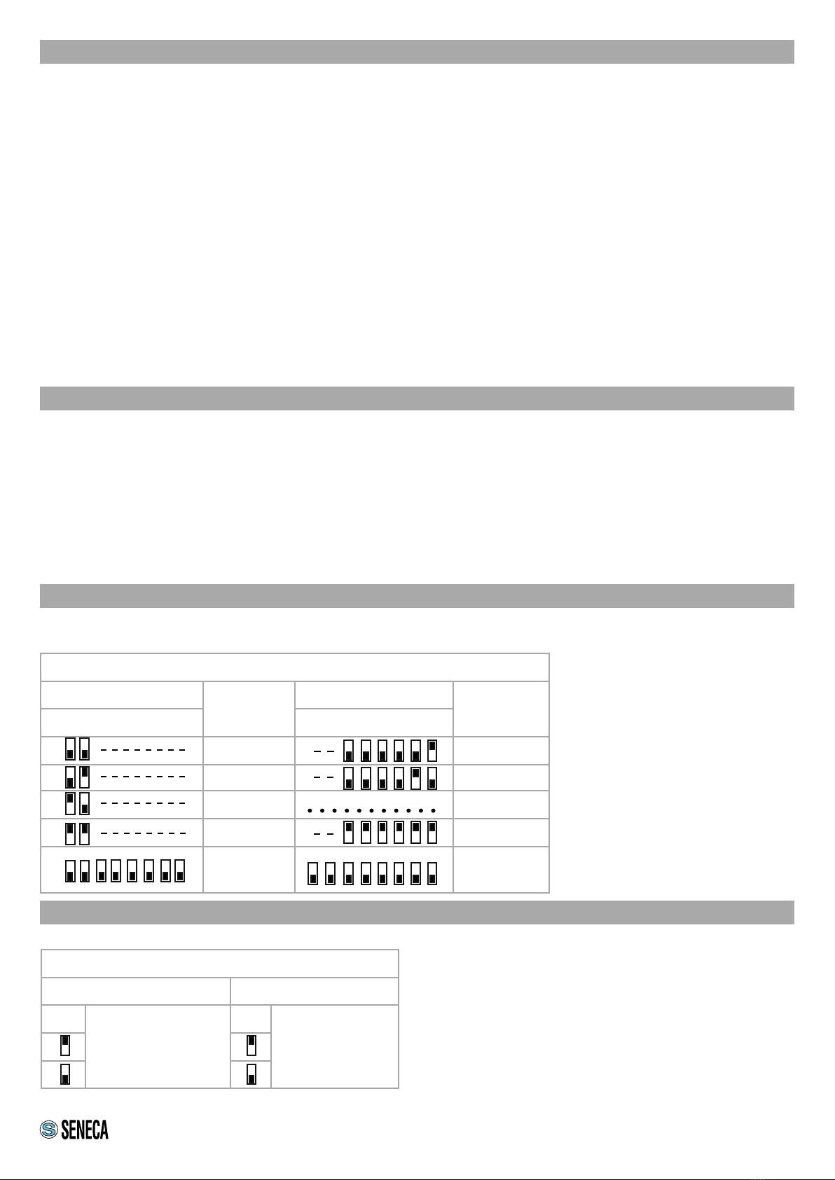
DIP-Switch status
SW1 POSITION BAUD
RATE
SW1 POSITION ADDRESS
1 2 3 4 5 6 7 8 1 2 3 4 5 6 7 8
9600 #1
19200 #2
38400 #...
57600 #63
From
EEPROM
From
EEPROM
Note: When DIP switches 3 to 8 are
OFF, the communication settings
are taken from programming
(EEPROM).
SETTING THE SW3 DIP-SWITCHES Z-SG / Z-SG2 VERSION
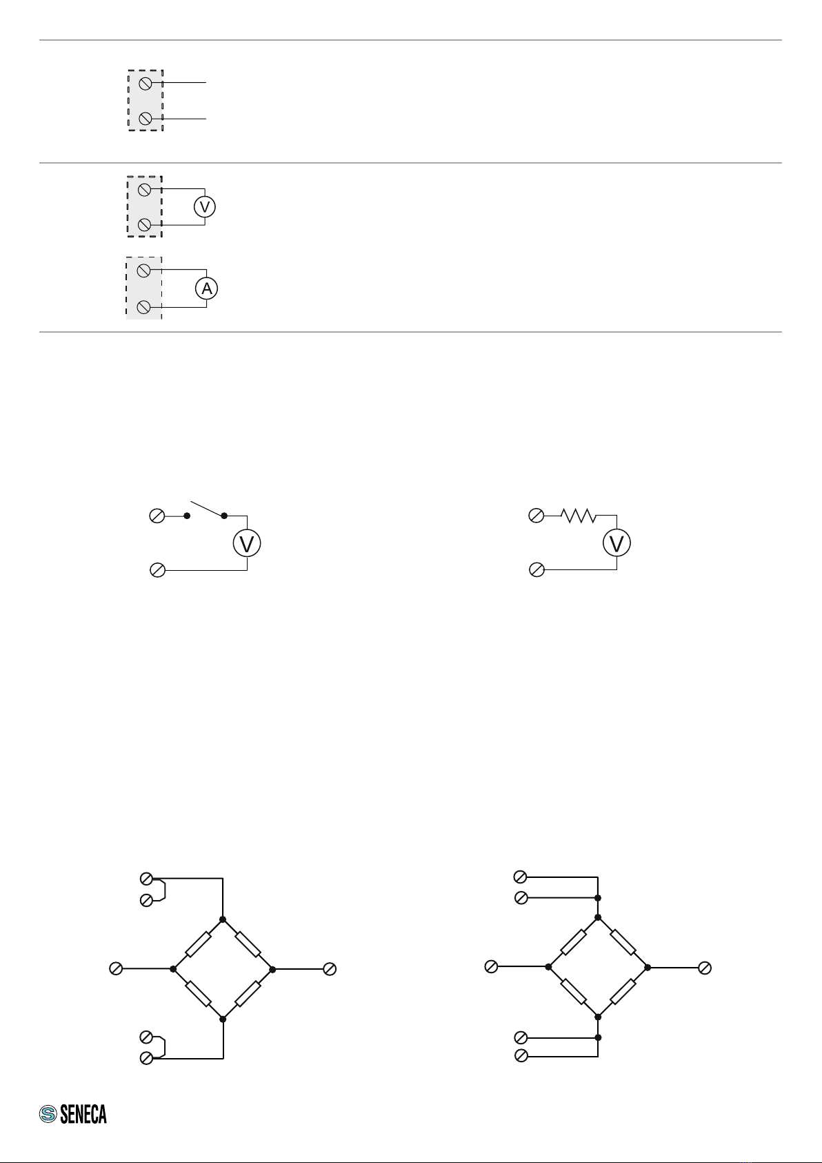
Status of the SW3 dip-switches
SW3 POSITION SW3 POSITION
1
RS485 terminator
2
GND interruption
Note 1:The RS485 line must be terminated only at the
ends of the communication line.
Note 2: Since the GND terminal of the RS485 port and the
negative terminal of the analogue output are not isolated
from each other, in order to use the analogue outputs
of several instruments simultaneously and connected
to each other via the RS485 port, it is necessary to
disconnect the GND terminal of the RS485 port via the
dedicated dip-switch (SW3). 4/8