NOTE: set the communication speed when the automatic line switching is set.
On the side of the module there are DIP switches that can be used to select the desired functions.
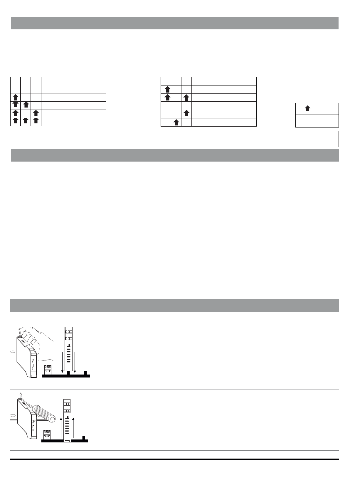
To select these functions, set the DIP switches as shown in the tables:
Communication speed selection: Selection of connection type and line switching:
SW1- Baud Rate SW1- Mode
INSTALLATION REGULATIONS
For optimal operation and long life, adequate ventilation must be provided for the module(s), avoiding
positioning channels that obstruct the ventilation louvers.
Avoid fitting modules above equipment that generates heat; you are advised to fit them at the bottom of
the panel.
NOTE: Use of the DIN guide connectors ensures practical fitting and correct ventilation of the modules.
To ensure correct operation of the converter, the following precautions should also be taken
in the installation phase:
-Use shielded cable for connections longer than three metres or in noisy environments (see section SERIAL
INTERFACE).
-Make the “serial” connections and set the dip-switches BEFORE powering the instrument.
-If using the converter with speeds below 9600 baud, the direction change must be set exclusively via
RTS line.
INSTALLATION ON AND REMOVAL FROM THE DIN IEC EN60715 RAIL
Insertion on the OMEGA IEC EN 60715 rail:
1)
Move the two hooks on the back of the module outwards as illustrated in
Fig.2.
2)
Insert the rear IDC10 connector of the module on a free slot of the OMEGA rail
accessory as shown in Fig. 1 . (insertion is univocal as connectors are polarised).
3)
To secure the module to the OMEGA rail, tighten the four hooks on the side
of the IDC10 rear connector as shown in Fig. 1.
Removal from the OMEGA IEC EN 60715 rail:
As illustrated in Fig.2:
1)
With the help of a screwdriver, pull the
two hooks on the side of the module
outwards.
2)
Extract the module from the rail.
DESCRIPTION
9600 BAUD
19200 BAUD
38400 BAUD
57600 BAUD
115200 BAUD
DESCRIPTION
HALF DUP. RTS
HALF DUP. AUTO
FULL DUP. RTS
FULL DUP. AUTO
FULL DUP. POINT TO POINT
t
Fig. 2
89
7
10 11 12
Z-8NTC
FAIL
x
x
x
RX
TX
YUSB
PWR
x
10 11 12
123
54 6
7 8 9
Fig. 1
89
7
10 11 12
Z-8NTC
FAIL
x
x
x
RX
TX
YUSB
PWR
x
10 11 12
21 3
54 6
7 8 9
KEY
ON
OFF
y
z