Seneca Z111 User manual

ENGLISH - 1/8MI00035 -E9
EN
FREQUENCY => CURRENT / VOLTAGE CONVERTER
Z111
GENERAL FEATURES
TECHNICAL SPECIFICATIONS
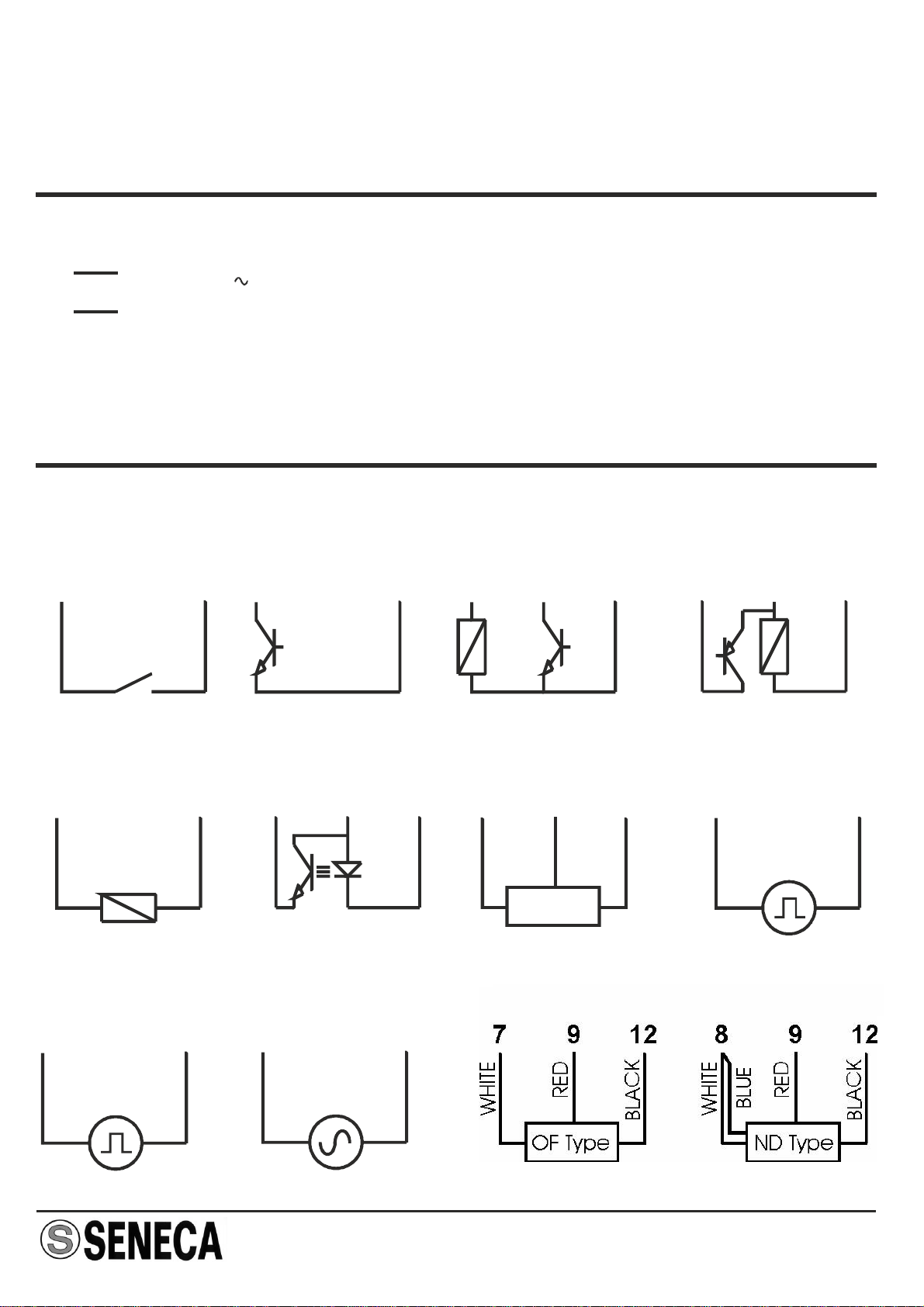
Pulse input for all the most commonly-used sensors: mechanical contact, reed, npn
with 2 and 4 wires, pnp with 3 wires and 24V DC power supply, Namur,
photoelectric, variable reluctance, 24V and TTL pulses
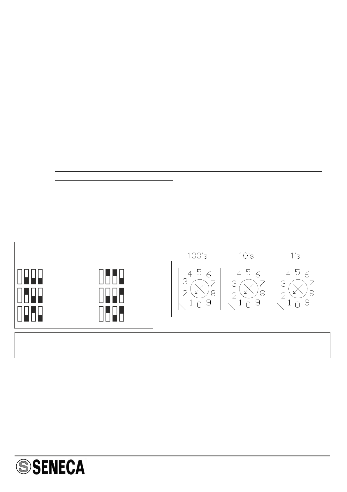
Maximum frequency from 1 mHz to 9.99 KHz, selectable fullscale from 10 mHz to
9.99 KHz;
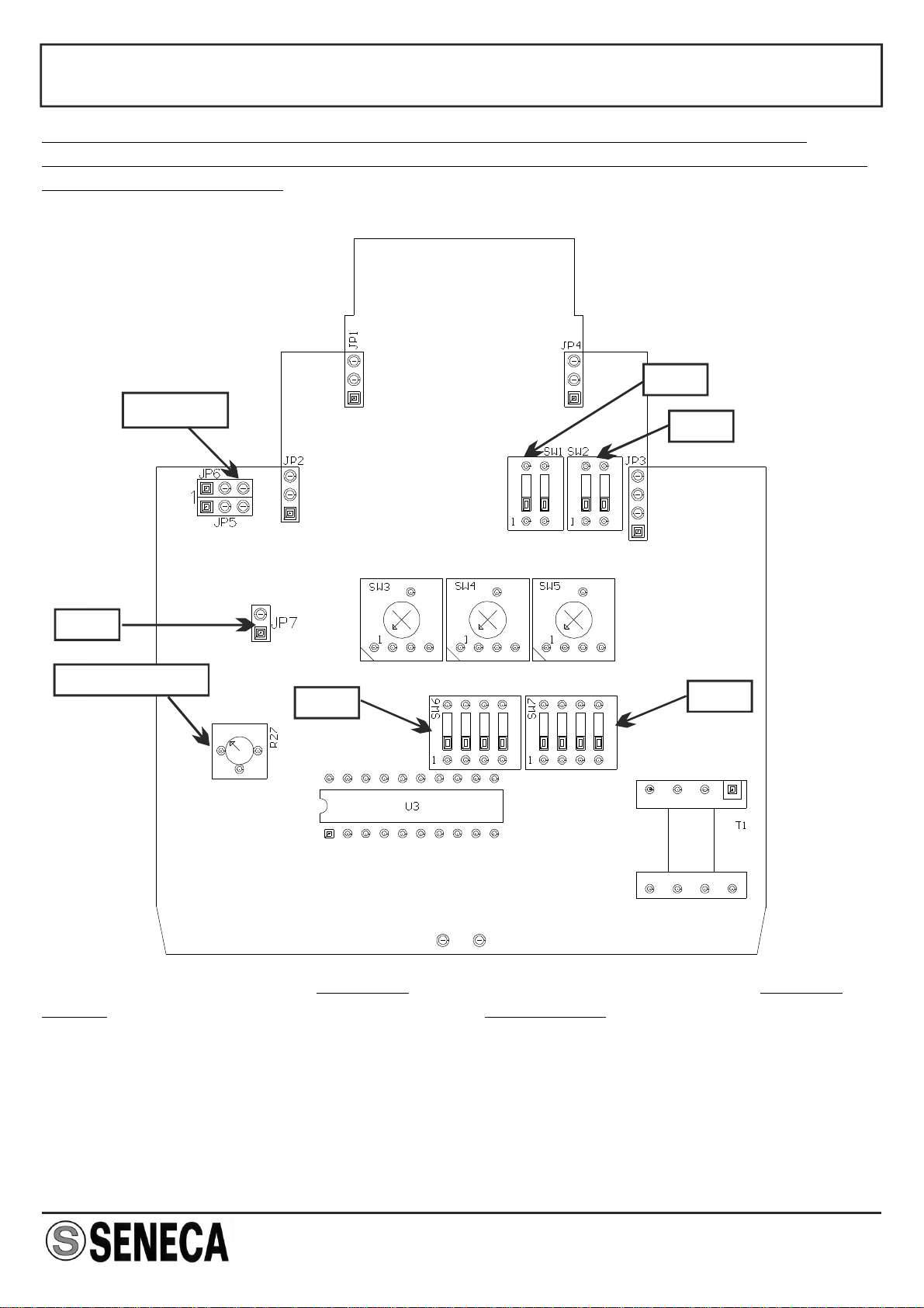
Full-scale can be easily set using rotating switches;
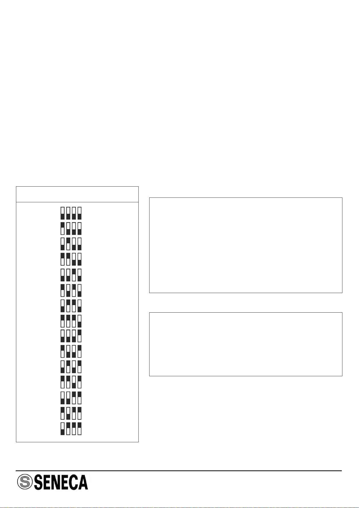
Selection of the output mode (0/4.20 mA, 0/1..5V , 0/2..10V) using dip-switches;
Possibility to set the number of pulses for the calculation of the pulse average;
Indication of power supply presence and out-of-scale errors provided on front panel;
3-point insulation: 1500V AC.
Power supply:
Input:
Output:
Work conditions:
Standards:
19..40 Vdc, 19..28 Vac 50..60 Hz, max 2,5 W
Pulses: mechanical contact, reed , npn with 2 and 3 wires ,
pnp with 3 wires and 24V DC power supply, Namur,
photoelectric, “HALL” sensor, and variable reluctance.
Maximum frequency 9.99 KHz
Active current 0..20 mA / 4..20 mA, max. load resistance: 600
ohm
Voltage 0..5 V / 0..10 V / 1..5 V / 2..10 V , min. load resistance:
2500 ohm
Error : < 0.3% of F.S.
Temperature: 0 - 50°C , Min. humidity: 30% , Max. humidity:
90% at 40°C (non condensing)
The instrument conforms to the following standards:
EN50081-2 (electromagnetic emission, industrial environments)
EN50082-2 (electromagnetic immunity, industrial environments)
EN61010-1 (safety)
Notes:
-Usewithcopperconductor.
-UseinPollutionDegree2Environment.
-PowerSupplymustbeClass2.
-WhensuppliedbyanIsolatedLimitedVoltage/Limited
Currentpowersupplyafuseratedmax2.5Ashallbe
installedinthefield.

MI00035 -E9 ENGLISH - 2/8
INSTALLATION RULES
The Z111 modules have been designed for mounting on DIN 46277 guides in vertical
position.
For long-lasting and optimum working life, the module(s) must be ensured adequate
ventilation. Make sure to position the cable raceways and any other objects in such
way as to avoid clogging the ventilation slots.
Also avoid positioning the modules above equipment that generates heat. For this
reason, we recommend performing installation in the lower part of the panel.
TAXING WORK CONDITIONS:
The following are considered taxing work conditions:
elevated power supply voltage (> 30V DC / > 26 V AC)
providing power supply to sensor input.
use of the active current output.
When paired modules are installed, inthey may require separation by at least 5 mm
the following cases:
With panel temperatures of more than 45°C in concomitance with at least one of the
taxing work conditions above.
With panel temperatures of more than 35°C in concomitance with at least two of the
taxing work conditions above.

MI00035 -E9 ENGLISH - 3/8
ELECTRICAL CONNECTIONS
POWER SUPPLY
INPUTS
We recommend using shielded cables for the connection of the signals; the shield must
be connected to a designated ground connection for the instrurmentation. We also
discourage passing the wires near the power supply cables for inverters, motors, or
induction ovens, etc.
19 ÷ 28 V
19 ÷ 40 V=
2
3
The power supply voltage must be between 19 and 40 V DC
(polarity not important), 19 and 28 V AC; also see the section
entitled“INSTALLATIONRULES”.
The upper limits must never be exceeded at the risk of
creatingseriousdamagetothemodule.
The power supply source must be protected against all risk of
modulemalfunction
by the use of an well sized fuse.
8
Contact / Reed
11
Photo-electric
7 9 10
NPN (2 wires)
8 11
+ -
NPN 24V (3 wires)
9 8 11
+ s -
NAMUR
7 9
-+
PNP 24V (3 wires)
7 9 11
s + -
“HALL” sensor
7 9 12
S + -7
Input 24V 11
+
7
TTL input 12
+
10
Variable reluctance
12
+
>100mV
Turbine or oval gear “AICHI”

NOTE : In order to permit the use of the variable reluctance type input, the internal
jumpers must be selected.
MI00035 -E9 ENGLISH - 4/8
Before setting the internal jumpers, the container's lateral closing panel must be
removed by pulling it slightly outward. The instrument is supplied with internal jumpers
set for standard inputs.
JP5-JP6 SW1
SW2
JP7
HISTERESYS SW6 SW7
Internal jumper setting for standard
inputs:
JP5 2-3in position
JP6 2-3in position
JP7 open
Internal jumper setting for variable
reluctance inputs:
in positionJP5 1-2
in positionJP6 1-2
closedJP7
Note: Pin number 1 on jumpers JP5 and JP6 stands on the left while looking at the
card from the front.

MI00035 -E9 ENGLISH - 5/8
HISTERESYS CALIBRATION
RETRANSMITTED OUTPUT
FILTER SETTING
Voltage Active current Ext. power supply current
Thisoperationisonlyperformedwhenthe“variablereluctance”inputisused.
For the hysteresis calibration, after first correctly setting the internal jumpers and the full-
scale frequency, a tester must be connected tothe device's output (it makes no difference
whether the voltage or current output is used) and an input signal must be provided; then
using a screwdriver, rotate the hysteresis trimmer completely counter-clockwise (the
tester should indicate 0) and then the trimmer must be slowly rotated clockwise until the
testerprovidesastableinput reading.Atthispoint,rotatethetrimmerclockwisebyaround
5%inordertohaveasufficientcalibrationsafetymargin.
NOTE : remember that the minimum signal amplitude is 100 mV.
1
6+
5
4+
1
5
+
SW6 - FILTER
Filter OFF
Filter ON
Whenever the input frequency is unstable, a filter can be set
to stabilise the output signal. In order to set this filter, position
SW6 ONdip-switch no. 1 in the position (by shifting it
upwards).
N.B.: The dip-switches must be set after first
disconnecting power supply from the module in order to
avoid damaging the module.
RESPONSE TIME
RANGE
x 0,0001
x 0,001
x 0,01
x 0,1
x 1
x 10
RESPONSE TIME
25 sec
2,5 sec
0,25 sec
0,25 sec
0,25 sec
0,25 sec
Led error after
1000 sec
100 sec
10 sec
10 sec
10 sec
10 sec

MI00035 -E9 ENGLISH - 6/8
INPUT FREQUENCY SETTING
Multiplier setting Frequency setting selectors
The input signal full-scale frequency can be easily set.
The three rotating selectors permit the setting of a value which when multiplied by the
multiplication factor will provide the input signal full-scale frequency.
Example 1 :
Example 2 :
NOTE 1 :
NOTE 2 :
if the input frequency full-scale value = 563 Hz, the hundredths (100's)
selector must be set to 5, the tenths (10's) selector must be set to 6,
and the units (1's) selector must be set to 3. The multiplier must be set to
x 1 (563 x 1 = 563 Hz).
if the input frequency full-scale value = 7850 Hz, the hundredths (100's)
selector must be set to 7, the tenths (10's) selector must be set to 8,
and the units (1's) selector must be set to 5. The multiplier must be set to
x 10 (7850 x 10 = 7850 Hz).
The hundredths selector (100's) cannot be set to 0; the minimum full-scale
value must therefore be 0,01 Hz.
The "Error" led blink if the input frequency is less lower than the values
indicated in the table or more than selected fullscale.
NOTE: Dip-switch and rotating selector setting must be performed after first
disconnecting module power supply in order to avoid damaging the module.
SW6 - MULTIPLIER
x 0.0001
x 0.001 x 0.1
x 1
x 0.01 x 10

MI00035 -E9 ENGLISH - 7/8
PULSE AVERAGE SETTING
Whenever the input signals present cyclically unstable frequency, a number of pulses
on which the frequency measurement will be calculated can be set.
Example : the input signal is provided by a proximity sensor that indicates the passage
of a number of bolts mounted on a wheel; if these bolts are not positioned
at equal distances, an unstable sensor output frequency value will occur
and this will create an unstable module Z11 output current and/or voltage
value.
By setting the number of bolts applied to the wheel, such as 10, for
example, as the “pulse average” , the device will count 10 pulses and then
divide the time that elapses between the first and the last pulse by 10. This
operation will permit an extremely stable module output signal to be
obtained.
1
2
3
4
5
6
7
8
9
10
11
12
13
14
15
SW7 - PULSE AVERAGE NOTE : if pulse average calculation is not
required, leave all the selector dip-SW7
switches (shifted down).OFF
NOTE: Dip-switch setting must be
performed after first disconnecting module
power supply in order to avoid damaging
the module.
NOTE: The minimum measured frequency is
normally . When the pulse average is0.001Hz
set over , the minimum frequency will be6 n /
6000.
Ex: pulse average = 8 ,
f.min = 8/6000 = 0.00133Hz.

MI00035 -E9 ENGLISH - 8/8
OUTPUT SELECTION
SW1 unit dip-switches number 1 and 2 permit
setting the setting of the output with or without
zero elevation respectively.
SW2 unit dip-switches permit the selection of
the output voltage.
NOTE: Dip-switch setting must be
performed after first disconnecting module
power supply in order to avoid damaging
the module.
0/1..5V
0/2..10V
SW2 - OUTPUT VOLTAGE
0..20mA/0..5V/0..10V
4..20mA/1..5V/2..10V
SW1 - OUTPUT MODE
Disposal of Electrical & Electronic Equipment (Applicable throughout the European Union and other
Europeancountrieswithseparatecollectionprograms)
Thissymbol,foundonyourproductoronitspackaging,indicatesthatthisproductshouldnotbetreatedas
household waste when you wish to dispose of it. Instead, it should be handed over to an applicable
collection point for the recycling of electrical and electronic equipment. By ensuring this product is
disposed of correctly, you will help prevent potential negative consequences to the environment and
humanhealth,whichcouldotherwisebecausedbyinappropriatedisposalofthisproduct.Therecyclingof
materialswillhelptoconservenaturalresources.Formoredetailedinformationabouttherecyclingofthis
product, please contact your local city office, waste disposal service or thè retail store where you
purchasedthisproduct.
SENECA s.r.l.
Via Austria, 26 - 35127 - PADOVA - ITALY
Tel. +39.049.8705355 - 8705359 - Fax +39.049.8706287
Thisdocumentisproperty ofSENECAsrl.Duplicationandreprodutionareforbidden,ifnotauthorized.Contentsofthe
presentdocumentationreferstoproductsandtechnologiesdescribedinit.Alltechnicaldatacontainedinthedocument
maybemodifiedwithoutpriornoticeContentofthisdocumentationissubjecttoperiodicalrevision.
Table of contents
Other Seneca Media Converter manuals

Seneca
Seneca Z109REG-BP User manual

Seneca
Seneca Z-8TC-SI User manual

Seneca
Seneca Z-MBus User manual

Seneca
Seneca Z201-H User manual

Seneca
Seneca Z-SG User manual

Seneca
Seneca Z Series User manual

Seneca
Seneca Z-SG3 User manual

Seneca
Seneca Z204-1 User manual

Seneca
Seneca K109UI User manual

Seneca
Seneca Z107 User manual

Seneca
Seneca Z-SG User manual

Seneca
Seneca EASY-USB User manual

Seneca
Seneca S117P1 User manual

Seneca
Seneca Z109UI2 User manual

Seneca
Seneca Z-SG User manual

Seneca
Seneca Z-SG2 User manual

Seneca
Seneca S117P1 User manual

Seneca
Seneca K109S User manual

Seneca
Seneca Z-SG3 User manual

Seneca
Seneca R-KEY-MBUS User manual