Seneca Z109REG-BP User manual

Installation
Manual
Installation
Manual
Installation
Manual
Installation
Manual
UNIVERSAL CONVERTER
WITH ISOLATED BIPOLAR OUTPUT
UNIVERSAL CONVERTER
WITH ISOLATED BIPOLAR OUTPUT
Serie Z
Serie Z
Z109REG-BP
Z109REG-BP
EN
EN
MI003471-E ENGLISH 1/8
SENECA
S
Contents:
- General specifications
- Technical specifications
- Installation rules
- Selection: input/ measuring scale
- Selection: output type
- Setting START and END at will
- Frontal LEDs indications’s
- Advanced settings
- Electrical connections
- Default conditions
- Purchase order codes
- Module layout
- Decommissioning and disposal
This document is property of SENECA srl. Duplication and reprodution are forbidden, if not authorized.
Contents of present documentation refers to products and technologies described in it. All technical data
contained in the document may be modified without notice. This document is subject to periodical revision.
SENECA s.r.l.
Via Austria, 26 – 35127 – PADOVA – ITALY
Tel. +39.049.8705355 - 8705359 - Fax +39.049.8706287
Manuals and configuration software are available at www.seneca.it

ENGLISH 2/8
MI003471-E
TECHNICAL SPECIFICATIONS
Universal Input
Sampling
frequency
Variable from 240 sps with 11 bit + sign resolution
to 15 sps with 15 bit + sign resolution (tipical values).
Filter
The input signal filter level can be enabled and configured: from
0.5 to 60 sec.
Response time
35 ms with 11 bit resolution, 140 ms with 16 bit resolution ( for
measures: voltage, current and potentiometer)
Voltage input mode
Bipolar from 75 mV to 20 V with 9 scales,
input impedance: 1 MMax resolution 15 bit + sign.
Current input mode
Bipolar up to 20 mA. Internal shunt 50. Max resolution .1A
Powered sensor loop: from sensor to module (passive module) or
from module to sensor(actvive module) by terminal 7
(Max 25 mA a Max 20 V) . with short-circuit protection
Automatic input out of range detection.
thermoresistances
(RTD) input mode
RTD type: PT100, PT500, PT1000, NI100, KTY81, NTC,
KTY84 -130/-150. Resistance measure 2, 3 or 4 wires and
resistance wire measure. Energising current: 0.56 mA.
Resolution 0.1 °C . Automatic burn-out detection.
For NTC resistance value < 25k.
NTC, KTY81 and KTY84 configurable only by software.
thermocouples (TC)
input mode
TC type: J, K, R, S, T, B, E, N. Input impedance: > 5 M
Automatic burn-out’s detection. Resolution 2.5 V.
Potentiometer input
mode
Excitation voltage of 300mV. Potentiometer input value
from 500 to 100 k (a R = 500parallel circuit must be added).
Automatic input out of range detection.
Rheostat input
Input rheostat value: from 500 to Max 25 k
GENERAL SPECIFICATIONS
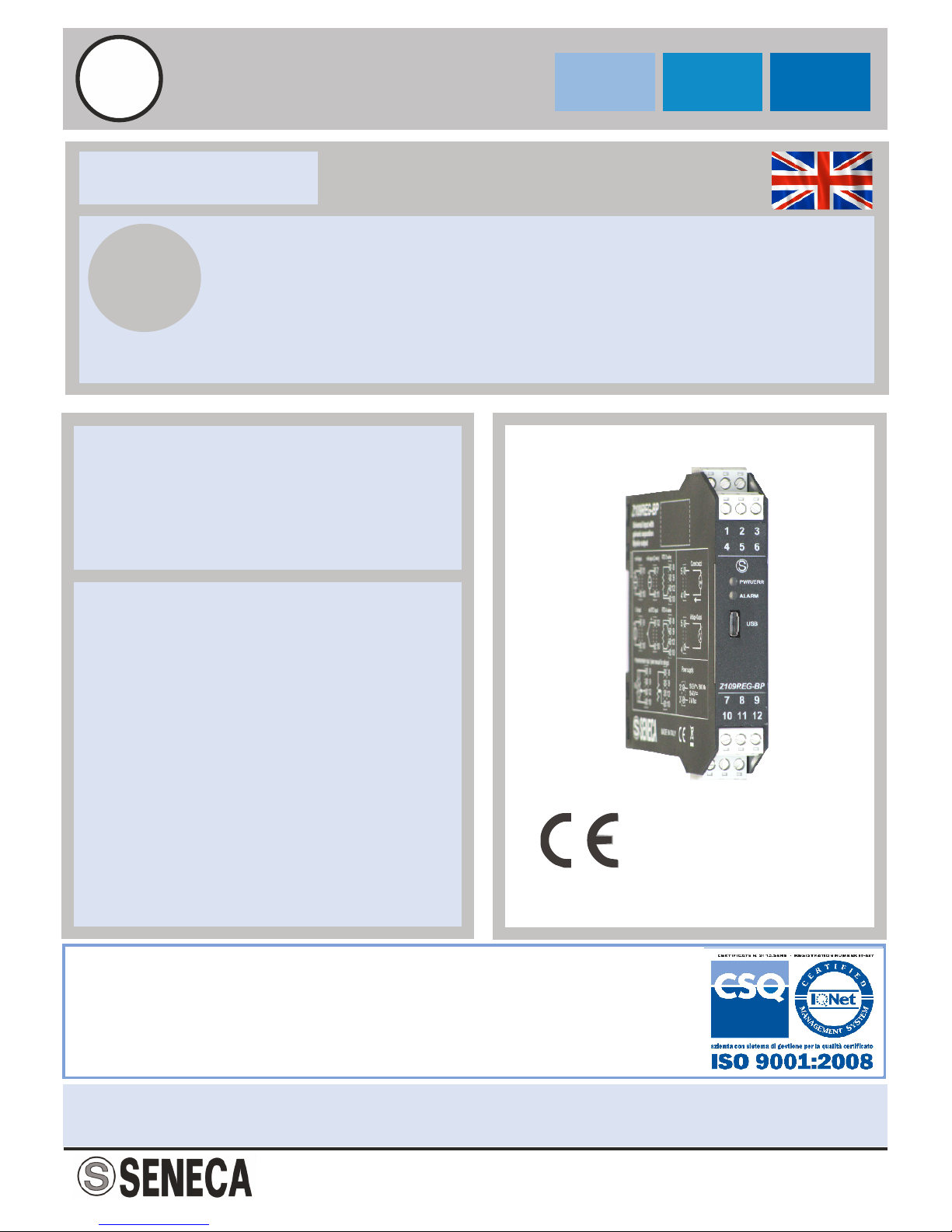
Universal input: voltage (mV), current (mA ), thermocouples C, T
RTDthermoresistances , potentiometer, rheostat, NTC.
Measurement and re-transmission on isolated analog bipolar output, with voltage output
or current.
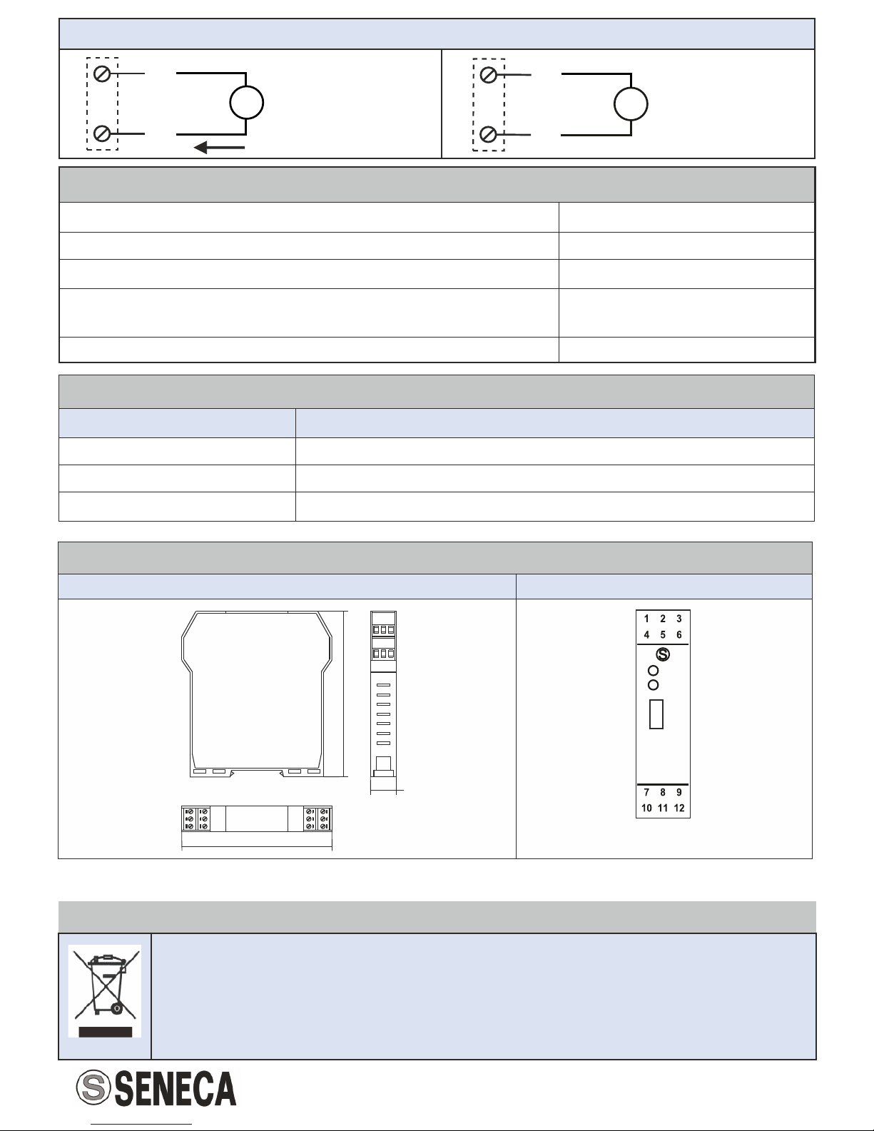
DIP-switch for selecting: type of input, START-END, output mode (zero elevation,
scale inversion), output voltage type (mA or V ).
2
Removable terminals with section of 2.5 mm
Possibility of USB configuration.
Sensor powered by 2 / 3 wire technique is available: 20V Max stabilised, 20mA Max
(terminal 7). with short-circuit protection
3-point insulation: 1500V .
Front panel indicating: power on, off scale or setting error and alarm status.
Facility for programming the following through PC: START-END scale, additional input
types, square root extraction, filter, burn-out etc. (See: www.seneca.it)

MI003471-E ENGLISH 3/8
(1) Influence of wire resistances: 0.1 uV/
(2) Output zero if t < 250°C
(3) RTD type: PT100, PT500, PT1000, NI100
All the errors have to be calculated with reference to resistive value.
(4) Influence of wire resistances: 0.005 %/, max 20
Errors related to max
measuring range
Accuracy
Thermal
stability
Linearity
error
EMI
TC input type: J, K, E, T, N
0.1%
0.01%/°K
0.2°C
<1% (1)
TC input type: R, S
0.1%
0.01%/°K
0.5°C
<1% (1)
TC input type: B (2)
0.1%
0.01%/°K
1.5°C
<1% (1)
Cold junction compensation
(for all TC inputs type)
2°C from 0°C to
50°C environment
/
/
/
Thermoresistance
input type (RTD) (3)
0.1%
0.01%/°K
t>0°C 0.02%
t<0°C 0.05%
<1% (4)
Potentiometer or rheostat
input type
0.1%
0.01%/°K
0.1%
<1%
Voltage or current input type
0.1%
0.01%/°K
0.05%
<1% (1)
Outputs
Channel numbers
1
Output type
Current: -20 – +20 mA, Maxium load resistance 500
Voltage: -10 – +10 V, minimum load resistance 1 k
Resolution
5 µA / 2.5 mV.
Environmental conditions
Temperature
-20 – +65°C
Humidity
30 – 90% a 40°C not condensing
Altitude
Up to 2000m a.s.l.
StorageTemperature
-20 – +85°C
Protection degree
IP20
Data Memory
EEPROM for all configuration data; storage time: 40 years.
Errors
Accuracy
Thermal stability
Voltage output
10 mV
0.5mV/K
Current output
20 µA
1µA/K

ENGLISH 4/8
MI003471-E
Standards
The module complies with the following standards:
EN61000-6-4 (electromagnetic emission,
industrial environment).
EN61000-6-2 (electromagnetic immunity,
industrial environment).
EN61010-1 (safety).
Isolations
1500 V
Power supply
Voltage
10 – 40 V;19 - 28 V 50 – 60 Hz
Consumption
Max: 2W
Dimensions / Module box
Dimensions
L: 100 mm; H: 112 mm; W: 17,5 mm
Module box
PA6, black
Electrical connections
Removable screw terminals3-way 5 mm pitch
MicroUSB frontal plug
Power supply
Input Output
1500V
INSTALLATION RULES
The module is designed to be installed, in vertical position, on DIN 46277 rail. For the best
module performance and long life, avoid to place cables raceways and other objects that
could obstruct ventilation slits.
Never install the modules near heat sources. We suggest to install the module in the bottom of
the control panel.
ADDITIONAL NOTES:
One max 2.5A fuse must be installed near the module.

MI003471-E ENGLISH 5/8
SELECTION: INPUT / MEASURING SCALE
The type of input is selected by setting the SW1 DIP-Switches group at the side of the
module.
Each type of input is matched with a number of beginnings scale (START) and full scale
(END) selectables with the SW2 DIP-Switches group.
The frames above show the START or END values for every selected input.
SW1
INPUT TYPE
1 2 3 4
V
/ Rheostat
mA
NI100
PT100
PT500
PT1000
Tc J
SW1
INPUT TYPE
1 2 3 4
Tc K
Tc R
Tc S
Tc T
Tc B
Tc E
Tc N
Potentiometer
SW2
START
1 2 3
1
2
3
4
5
6
7
8
SW2
END
4 5 6
1
2
3
4
5
6
7
8
1 2 3 4 5 6 7 8
SW2 DIP -Switch in OFF position
Start End
SW2
DIP
N°
Voltage
Resistance /
Rheostat
Current
Potentiometer
NI100 (RTD)
PT100 (RTD)
START
END
START
END
START
END
START
END
START
END
START
END
1
(*)
(*)
(*)
(*)
(*)
(*)
(*)
(*)
(*)
(*)
(*)
(*)
2
0 V
100 mV
0
1 k
0 mA
1 mA
0 %
40 %
-50°C
20°C
-200°C
50°C
3
400 mV
200 mV
0.5 k
2 k
1 mA
2 mA
10 %
50 %
-30°C
40°C
-100°C
100°C
4
1 V
500 mV
1 k
3 k
4 mA
3 mA
20 %
60 %
-20°C
50°C
-50°C
200°C
5
2 V
1 V
2 k
5 k
-1 mA
4 mA
30 %
70 %
0°C
80°C
0°C
300°C
6
-5 V
5 V
5 k
10 k
-5 mA
5 mA
40 %
80 %
20°C
100°C
50°C
400°C
7
-10 V
10 V
10 k
15 k
-10 mA
10 mA
50 %
90 %
30°C
150°C
100°C
500°C
8
-20 V
20 V
15 k
25 k
-20 mA
20 mA
60 %
100 %
50°C
200°C
200°C
600°C
SW2
DIP
N°
PT500 (RTD)
PT1000 (RTD)
Thermocouple J
Thermocouple K
Thermocouple R
Thermocouple S
START
END
START
END
START
END
START
END
START
END
START
END
1
(*)
(*)
(*)
(*)
(*)
(*)
(*)
(*)
(*)
(*)
(*)
(*)
2
-200°C
0°C
-200°C
0°C
-200°C
100°C
-200°C
200°C
0°C
400°C
0°C
400°C
3
-100°C
50°C
-100°C
50°C
-100°C
200°C
-100°C
400°C
100°C
600°C
100°C
600°C
4
-50°C
100°C
-50°C
100°C
0°C
300°C
0°C
600°C
200°C
800°C
200°C
800°C
5
0°C
150°C
0°C
150°C
100°C
400°C
100°C
800°C
300°C
1000°C
300°C
1000°C
6
50°C
200°C
50°C
200°C
200°C
500°C
200°C
1000°C
400°C
1200°C
400°C
1200°C
7
100°C
300°C
100°C
300°C
300°C
800°C
300°C
1200°C
600°C
1400°C
600°C
1400°C
8
150°C
400°C
200°C
400°C
500°C
1000°C
500°C
1300°C
800°C
1750°C
800°C
1750°C

MI003471-E ENGLISH 6/8
SW2
DIP
N°
Thermocouple T
Thermocouple B
Thermocouple E
Thermocouple N
START
END
START
END
START
END
START
END
1
(*)
(*)
(*)
(*)
(*)
(*)
(*)
(*)
2
-200°C
50°C
0°C
500°C
-200°C
50°C
-200°C
200°C
3
-100°C
100°C
500°C
600°C
-100°C
100°C
-100°C
400°C
4
-50°C
150°C
600°C
800°C
0°C
200°C
0°C
600°C
5
0°C
200°C
700°C
1000°C
100°C
300°C
100°C
800°C
6
50°C
250°C
800°C
1200°C
150°C
400°C
200°C
1000°C
7
100°C
300°C
1000°C
1500°C
200°C
600°C
300°C
1200°C
8
150°C
400°C
1200°C
1800°C
400°C
800°C
500°C
1300°C
Beware:
DIP-switches must be set
while the module is
powered down, otherwise,
the module may be
damaged.
(*) START or END
are set in memory with the PC or
with a programming push buttons.
SETTING START AND END AT WILL
The START and END push-buttons under the SW2 DIP-switch group allow to set the beginning and end
scale at will within the scale pre-set through the dip-switches.
To obtain this facility it is necessary to use a suitable signal generator, able to furnish the desired values of
beginning and end scale.
The procedure is following:
1. Set to SW1 the type of input desired, set to SW2 a START and END measurement which include
the required beginning and end values.
2. Power up the module.
3. Supply a calibrator or simulator of the signal you wish to measure and re-transmit.
4. Set the required START value on the calibrator (or other instrument).
5. Press the START push-button for at least 3 sec.
The green LED on the front panel flashes to indicate the value has been stored.
6. Set the required END value on the calibrator (or other instrument)
7. Press the END push-button for at least 3 sec.
The green LED on the front panel flashes to indicate the value has been stored.
8. Cut power to the module and set to OFF position the dip-switches of group SW2,
Like in SW2 DIP frame: START and END values row n°1 (*).
The module is now configured for the required start and end scale.
To reprogram it (e.g. for a different type of input) repeat the whole procedure.
SELECTION: OUTPUT TYPE
SW2 DIP-switches group numbers 7 and 8 enable you to set the output mode: voltage or current and
the output mode: normal or reversed.
SW2
OUTPUT TYPE
7
Current
Voltage
SW2
OUTPUT TYPE
8
Normal
Reversed
FRONTAL LEDS INDICATIONS’S
LED
STATE
MEANING OF LEDS
PWR Green
On
Power supply presence
PWR Green
Flashing (freq: 1 Flash./sec)
Out of range, Burn Out
PWR Green
Flashing (freq 2 Flash./sec)
DIP-Switch setting Error’s
ALARM Yellow
On
Internal fault

Universal input
MI003471-E ENGLISH 7/8
Potentiometer input:
One R = 500Ω resistance
parallel circuit is needed.
Potentiometer value must
be from1 kΩ to 100kΩ
Thermocouple input type:
J, K, R, S, T, B, E and N.
Input voltage for
Full scale < 150 mV
Passive current input (-20 – +20 mA).
The sensor supplies the current loop.
Use this connection if the input
current come from outside.
Active current input (-20 – +20 mA).
The module supplies the current loop.
Use this connection with 2 wire
measurement. The transducer is
powered by the module Z109REG-BP.
Thermoresistance input type:
PT100, NI100, PT500 and PT1000.
The two-wire connection can also be
used for NTC and KTY
ADVANCED SETTINGS
By using a PC and downloadable softwares from , it is possible to set other normally fixedwww.seneca.it
parameters in addition to start and end scale:
Additional input types.
Digital filter (normally disabled).
Square root extraction (normally disabled).
Negative burn-out (normally positive).
Start and end scale of the analog output.
Value of the analog output in case of error.
Rejection programmable for 50 or 60 Hz mains frequency (normally set to 50 Hz).
Sampling frequency/resolution (normally set to 15 sps/16 bit).
3 or 4 wires measure for thermal resistance (normally set to 3 wires).
The instructions for setting and USB cable are supplied as a KIT available on request.
ELECTRICAL CONNECTIONS
Power supply
The supply voltage must be between 10 to 40 V (Any polarity) or between 19 e 28 V.
The upper limits must not be exceeded to avoid serious damage to the module.
any failure of the module using It’s necessary to protect the power supply source against
appropriately sized fuse (Max = 2.5A).
2
3
19 – 28 V
50 – 60 Hz
10 – 40 V
2 W Max
10
12
9
POT
8
R
mV/TC
10
12
+
10
11
7
11
10
9
+
Voltage input (-20 – +20 V)
Full scale > 150 mV
10
9
8
12
4-wire
12
10
9
8
RTD
3-wire
12
10
9
8
RTD
2-wire
12
10
9
8
RTD
Rheostat input:
values from 500 Ω to
25 kΩ are needed

ENGLISH 8/8
MI003471-E
PURCHASE ORDER CODE
Order code
Description
Z109REG-BP
Bipolar universal converter with galvanic separation
KIT-USB
USB cable and configuration software
CAVO-USB-A-MICRO-B
USB / microUSB cable
DEFAULT CONDITIONS
Input type / Start – End range
Voltage / -10 V – +10 V
Input filter (acquired signal)
Disabled
Output type / Start – End range
Voltage / -10 V – +10 V
Reiection at mains frequency /
Sampling time
Reiection = 50Hz /
Sampling time = 20ms
Cold junction compensation ( for RTc input)
Disabled
Variations of standard parameters are possible by software (see www.seneca.it).
For more information about a list of all register and their function consult the USER manual.
DECOMMISSIONING AND DISPOSAL
Disposal of Electrical & Electronic Equipment (Applicable throughout the European Union and other European
countries with separate collections programs). This symbol, found on your product or on its packaging, indicates
that this product should not be treated as household waste when you wish to dispose of it. Instead, it should be
handed over to an applicable collection point for the recycling of electrical & electronic equipment. By ensuring this
product is disposed of correctly, you will help prevent potential negative consequences to the environment and
human health, which could otherwise be caused by inappropriate disposal of this product. The recycling of
materials will help to conserve natural resources. For more detailed information about the recycling of the product,
please contact your local city office, waste disposal service of the retail store where you purchased this product.
MODULE LAYOUT
MODULE DIMENSIONS
FRONT PANEL
Z109REG-BP
PWR/ERR
x
x
USB
ALARM
Y
Voltage output
5
4
V
+
Current output
5
4
mA
+
Output
112 mm
17,5 mm
100,0 mm
Table of contents
Other Seneca Media Converter manuals

Seneca
Seneca Z111 User manual

Seneca
Seneca Z-SG3 User manual

Seneca
Seneca S117P1 User manual

Seneca
Seneca R-KEY-MBUS User manual

Seneca
Seneca Z109REG-BP User manual

Seneca
Seneca Z Series User manual

Seneca
Seneca Z-SG User manual

Seneca
Seneca Z-SG3 User manual

Seneca
Seneca Z-MBus User manual

Seneca
Seneca Z-SG2-L User manual

Seneca
Seneca S107USB User manual

Seneca
Seneca Z-SG2 User manual

Seneca
Seneca Z-SG User manual

Seneca
Seneca EASY-USB User manual

Seneca
Seneca K109S User manual

Seneca
Seneca Z-SG User manual

Seneca
Seneca Z201-H User manual

Seneca
Seneca Z-8TC-SI User manual

Seneca
Seneca Z204-1 User manual

Seneca
Seneca Z Series User manual