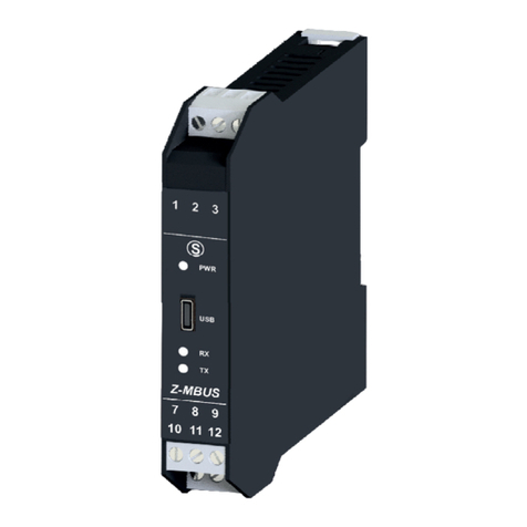
Seneca Z109UI2 User manual

ENGLISH 1/8
MI004301-E
This document is property of SENECA srl. Duplication and reproduction of it are forbidden (though partial), if not authorized.
Contents of present documentation refers to products and technologies described in it. Though we strive for reach perfection
continually, all technical data contained in this document may be modified or added due to technical and commercial needs.
It’s impossible eliminate mismatches and discordances completely. Contents of present documentation is anyhow subjected to
periodical revision. If you have any questions don’t hesitate to contact our structure or to write us to e-mail addresses as above
mentioned.
SENECA s.r.l.
Via Austria, 26 – 35127 – PADOVA – ITALY
Tel. +39.049.8705355 – 8705359 Fax. +39.049.8706287
Internet site: Technical assistance: www.seneca.it [email protected]
Commercial reference: [email protected]
Chapter index
Page
1. Preliminary warnings
2
2. Description and characteristics
2.1 Module description
2.2 General characteristics and features
2
3. Technical specifications
3.1 Input
3.2 Outputs
3.3 Connections
3.4 Power supply
3.5 Module case
3.6 Environmental conditions
2
4. Preliminary instructions for use
4
5. Electrical connections
5.1 Safety measures before use
5.2 USB interface
5.3 Connections
5.4 Power supply
5.5 Voltage or current input
5.6 Analog output
4
6. Configuration
6.1 Input selection / Measuring scale
6.2 START and END setting at will
6.3 Output selection
6.4 Configuration through a PC
6.5 Jumpers position
6.6 LED indications on the frontal panel
6
7. Purchase order code
8
8. Module layout
8
9. Decommissioning and disposal
8
USER MANUAL Z Line
Z109UI2-1
V - mA
converter module
with galvanic insulation
EN

ENGLISH 2/8
MI004301-E
Voltage input:
Bipolar from 100 mV up to 20 V in 9 scales, input impedance 1 M,
resolution max 15 bit + sign.
Current input:
Bipolar up to 20 mA, input impedance ~ 50 , resolution: 1A.
Sampling frequency:
240 sps with 11 bits resolution.
Response time:
35 ms with 11 bits resolution.
3. TECHNICAL SPECIFICATIONS
3.1 INPUT
2.2 GENERAL CHARACTERISTICS AND FEATURES
input type: V or mA.Voltage or current
Sensor powered by 2-wire technique: 20 V stabilised, 20mA max, short-circuit protected.
Measurement and re-transmission on isolated analog output, with voltage and current output.
DIP-switch for selecting: type of input, START-END, output mode
(zero elevation, scale inversion), output type (mA or V ).
Front panel indicating: power on, off scale or setting error.
3-points insulation: 1500 V.
Output:
I: 0-20 / 4-20 mA, max load resistance 600
V: 0-5 V / 0-10 V / 1-5 V / 2-10 V, min load resistance 2 k
Resolution: 2.5 A / 1.25 mV.
Data memory:
EEPROM for all configuration data; storage time: 40 years.
3.2 OUTPUTS
The Z109UI2 module acquires an voltage or current input signal, converts it to an analog format and send it to
an universal isolated output.
2. DESCRIPTION AND CHARACTERISTICS
2.1 MODULE DESCRIPTION

ENGLISH 3/8
MI004301-E
3.3 CONNECTIONS
USB Interface
Micro USB connector (frontal panel)
3.4 POWER SUPPLY
Supply Voltage
10-40 V, 19-28 V 50-60 Hz, through screw terminals: 2 – 3
Power supply unit
Classe 2
Power consumption
1.6 W @ 24 V with output 20 mA; Max: 2.5 W
3.5 MODULE CASE
Case
PA6, black color
Dimensions
Width L=100mm; Height H=112mm; Depth W=17,5mm
Board terminals
2
Removable 3 way screw terminals: pitch 5.08mm, section 2.5mm
Protection class
IP20
3.6 ENVIRONMENTAL CONDITIONS
Operating
Temperature
-10°C – +60°C (UL: -10°C – +60°C)
INSULATIONS 1500V
STANDARDS
The module complies with the following standards:
EN61000-6-4 (electromagnetic emission,
in industrial environment)
EN61000-6-2 (electromagnetic immunity,
in industrial environment)
EN61010-1 (safety)
Notes:
- Use with copper conductor.
- Use in Pollution Degree 2 Environment
- Power Supply must be Class 2
- When supplied by an Isolated Limited Voltage and/or
Limited Current power supply, a fuse rated max 2.5 A
shall be installed in the field.
1500 V insulating voltage is among:
- power supply
- analog input
- analog output
23
6
USB
POWERSUPPLY
1
ANALOG
OUT
10
11
12
9
8
7
1500 V
V - mA
INPUT
Errors referred to maximum
measuring range:
Calibration
Error
Thermal
Coefficient
Linearity
Error
EMI (1)
Voltage / Current input
0.1%
0.01%/°K
0.05 %
<1%
Voltage output (2)
0.3%
0.01%/°K
0.01%
(1) EMI: electromagnetic interference.
(2) Values to be added to the errors of the selected input.

ENGLISH 4/8
MI004301-E
3.6 ENVIRONMENTAL CONDITIONS
Humidity
30 – 90 % a 40°C not condensing
Pollution degree
2 (Maximum environment pollution during operations)
Storage Temperature
-20°C – +85°C
The module was designed to be installed on omega IEC EN 60715 rail in vertical position.
We suggest the module installation in the lower part of the control panel.
In order to ensure best performance and longest working life module, please ensure adequated ventilation to
the modules and avoid placing raceways or other objects which obstructs the ventilation slots.
It’s forbidden ti install the module near or above heat sources.
«Severe operating conditions» are as follows:
- High power supply voltage: >30 V , 26 V.
- The module supplies power to the sensor at input.
- Output used as current generator (connected to a passive module).
If the modules are installed side by side, separate them by at least 5 mm in the following cases:
-If the panel operating temperature exceeds 45°C and at least one of the severe operating conditions exists;
-If the panel operating temperature exceeds 35°C and at least two of the severe operating conditions exist.
4. PRELIMINARY INSTRUCTIONS FOR USE
To satisfy the electromagnetic compliance requirements:
Use shielded cables for signals transmission;
The cable shield must be connected to an earth wire used specifically for instrumentation;
Avoid placing signal cables near power cables and power appliances (inverters, motors,
induction ovens etc...).
5. ELECTRICAL CONNECTIONS
5.1 SAFETY MEASURES BEFORE USE
The module has a microUSB connector, you can configure it through APP and/or software.
For more information please see .www.seneca.it/products/z109ui2
Y
x
Z109UI2
USB
PWR
CU-A-MICRO-OTG CU-A-MICROB
CU-A-MICROB
5.2 USB INTERFACE
5.3 CONNECTIONS
Please provide the module with supply voltage < 40 V or < 28 V.
These upper limits must not be exceeded to avoid serious damage to the module.
5.4 POWER SUPPLY
2
3
19 – 28 V
10 – 40 V
2.5 W Max

ENGLISH 5/8
MI004301-E
(3) Powered active output to be connected to passive inputs.
(4) Unpowered passive output to be connected to active inputs.
In order to select this feature please see: SETTINGS THROUGH INTERNAL JUMPERS.
RE-TRANSMITTED OUTPUT
+
V output
1
6
V
Voltage
mA output
1
6+
A
Generated
current (3)
mA output
External power
Supply current (4)
1
6
+
A+
5.6 ANALOG OUTPUT
Electrical ratings for UL:
Output: 10 V, 20 mA
Input: 20 V, 20 mA
Operating Temp.: -20 – +60°C
5.5 INPUTVOLTAGE OR CURRENT
10
12
VOLTAGE
INPUT: mV
V input < 150mV
10
9
+
V input > 150 mV
VOLTAGE
INPUT: V
The sensor power
the loop (mA)
Passive module
10(-)
11(+)
+
mA input
The module power
the loop (mA)
Active module
11(-)
7(+)
+
mA input (2 wires)
CURRENT INPUT
+

ENGLISH 6/8
MI004301-E
6. CONFIGURATION
6.1 INPUT SELECTION / MEASURING SCALE
You can select the type of input by setting SW1 DIP switches placed on the side of the module.
Every type of input is matched to a certain number of beginning and end scale values which can be
selected through SW2 DIP switches.
The following table lists possible START and END values according to the type of input selected.
The left column show the DIP-switches setting in order to select the START and END scale desired.
SW1: INPUT SELECTION
POSITIO
N
INPUT
POSITION
INPUT
1 2 3 4
TYPE
1 2 3 4
TYPE
V
mA
SW2: START and END
POSITIO
N
START
POSITIO
N
END
1 2 3
SCALE n°
4 5 6
SCALE n°
1
1
2
2
3
3
4
4
5
5
6
6
7
7
8
8
LEGENDA
ON
OFF
SW2 DIP-switch in OFF position
(*)START and END setted in the memory by a PC or by the programming push-buttons.
Note: DIP-switches must be set while the module is powered down, otherwise,
the module may be damaged.
1 2 3 4 5 6 7 8
SCALE n°
Voltage
Current
START
END
START
END
1
(*)
(*)
(*)
(*)
2
0 V
100 mV
0 mA
1 mA
3
400 mV
200 mV
1 mA
2 mA
4
1 V
500 mV
4 mA
3 mA
5
2 V
1 V
-1 mA
4 mA
6
-5 V
5 V
-5 mA
5 mA
7
-10 V
10 V
-10 mA
10 mA
8
-20 V
20 V
-20 mA
20 mA

ENGLISH 7/8
MI004301-E
SW2: SCALE AND MODE OUTPUT
POSITION
OUTPUT
POSITION
OUTPUT
7 8
RANGE
7 8
MODE
X
0..20mA / 0..10V
X
NORMAL
X
4..20mA / 2..10V
X
REVERSE
SW3: OUTPUT TYPE
POSITION
OUTPUT
POSITION
OUTPUT
1 2
TYPE
1 2
TYPE
VOLTAGE
CURRENT
LEGEND
ON
OFF
6.4 CONFIGURATION THROUGH A PC
By using a PC and EASY SETUP software, it is possible to set: input type, input start and end of scale,
measurement type, rejection filter, resolution, output type, output start and end of scale, conversion value,
upper and lower limits, output value if there is an error and digital output filter.
The START and END push-buttons under the SW2 DIP-switch group allow to set the beginning and end
scale at will, within the scale pre-set through the dip-switches. To obtain this facility it is necessary to use
a suitable signal generator, able to furnish the desidered values of beginning and end scale.
The procedure is following:
1. Set through dip-switches the type of input, START and END measurement which include the required
beginning and end values.
2. Power up the module.
3. Supply a calibrator or simulator of the signal you wish to measure and re-transmit.
4. Set the required START value on the calibrator (or other instrument).
5. Press the START push-button for at least 3 sec. The green LED on the front panel flashes to indicate
the value has been stored.
6. Repeat points 4 and 5 for the required END value.
7. Power off the module and set to OFF position the dip-switches of group SW2, correspondent to the
settings of START and END values.
The module is now configured for the required start and end scale.
In order to re-program it (e.g. for a different type of input) repeat the whole procedure.
6.2 START AND END SETTING AT WILL
SW2 group DIP-switches 7 and 8 enable you to set the output with or without zero elevation and/or
as a normal or reversed output. The SW3 DIP-switch group enables you to select the output type.
Note:The DIP-switches must be set while the module is powered down, avoiding electrostatic
discharge, otherwise the module may be damaged.
6.3 OUTPUT SELECTION

ENGLISH 8/8
MI004301-E
SETTINGS THROUGH
INTERNAL JUMPERS
ACTIVE / PASSIVE OUTPUT
Active Output Passive Output
J9
SW1
SW2
SW3
FRONTAL PANEL
MODULE DIMENSIONS
Disposal of Electrical & Electronic Equipment (Applicable throughout the European Union and
other European countries with separate collections programs). This symbol, found on your
product or on its packaging, indicates that this product should not be treated as household waste
when you wish to dispose of it. Instead, it should be handed over to an applicable collection point
for the recycling of electrical & electronic equipment. By ensuring this product is disposed of
correctly, you will help prevent potential negative consequences to the environment and human
health, which could otherwise be caused by inappropriate disposal of this product. The recycling of
materials will help to conserve natural resources. For more detailed information about the
recycling of the product, please contact your local city office, waste disposal service of the retail
store where you purchased this product.
9. DECOMMISSIONING AND DISPOSAL
8. MODULE LAYOUT
ORDER CODE
SPECIFICATIONS
CU-A-MICROB
USB-microUSB 1 mt communication cable.
CU-A-MICRO-OTG
Adapter cable for smartphone.
7. PURCHASE ORDER CODE
LED
LED STATE
LED MEANING
PWR
Green
ON
Power supply presence
Blinking (freq: 1 flash./sec)
Out of Scale, Burn Out or Internal failure
Blinking (freq 2 flash./sec)
DIP-switches setting error
6.6 LED INDICATIONS ON THE FRONTAL PANEL
6.5 JUMPERS POSITION
J9 J9
Z109UI2-1
USB
PWR/
FAIL
1112
10
111.0 mm
17.5 mm
100 mm
MADE IN ITALY
USB
Z109TC2-1
PWR/
FAIL
89
7
1
6
V Output*
V
+2
3
19-28 V 50-60 Hz
10-40 V
2,5 W Max
Class 2
Power Supply
*Please see manual about Active / Passive setting
OUTPUT
1
6
mA Output*
A
+
1
6
mA Output*
A
+
+
ET004362B
Z109UI2-1
V - mA Transmitter
with galvanic insulation
V - mV input
INPUT
mA input (2 Wire)mA input
10
11
+
11
7
+
10
9
+
Electrical ratings for UL standards:
OUTPUT: 10 V , 20 mA
INPUT: 20 V , 20 mA
OPERATING TEMP.: -20 - +60 °C
This manual suits for next models
1
Table of contents
Other Seneca Media Converter manuals

Seneca
Seneca K109UI User manual

Seneca
Seneca Z109REG-BP User manual

Seneca
Seneca Z201 User manual

Seneca
Seneca R-KEY-MBUS User manual

Seneca
Seneca ZC-SG User manual

Seneca
Seneca Z-8TC-SI User manual

Seneca
Seneca Z107 User manual

Seneca
Seneca Z-SG3 User manual

Seneca
Seneca Z-SG2-L User manual

Seneca
Seneca Z-4RTD2 User manual

Seneca
Seneca Z204-1 User manual

Seneca
Seneca Z Series User manual

Seneca
Seneca Z111 User manual

Seneca
Seneca K109S User manual

Seneca
Seneca Z-MBus User manual

Seneca
Seneca Z109REG-BP User manual

Seneca
Seneca Z-SG User manual

Seneca
Seneca Z201-H User manual

Seneca
Seneca S117P1 User manual

Seneca
Seneca EASY-USB User manual