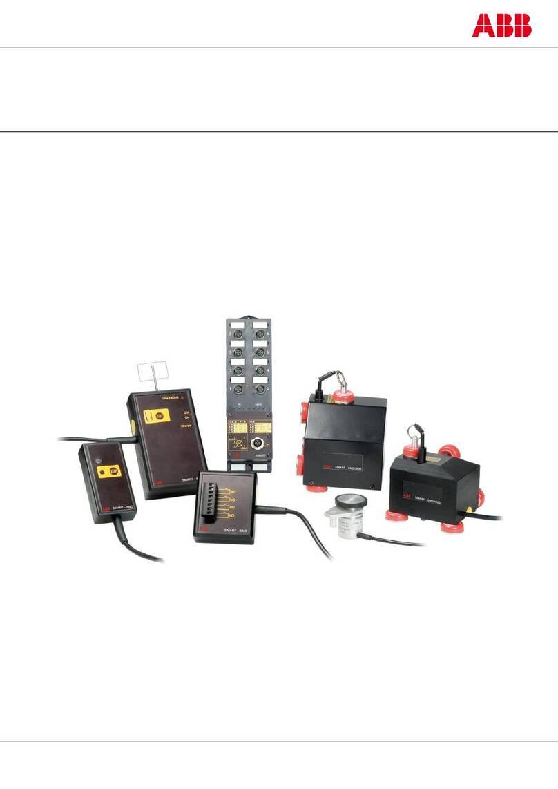
ABB SM1000 User manual

User Guide Supplement –
Ethernet Communications Option
IM/SMENET Issue 4
Videographic Recorders
SM1000 and SM2000

ABB
EN ISO 9001:2000
Cert. No. Q 05907
EN 29001 (ISO 9001)
Lenno, Italy – Cert. No. 9/90A
Stonehouse, U.K.
0255
Electrical Safety
This equipment complies with the requirements of CEI/IEC 61010-1:2001-2 'Safety Requirements for Electrical Equipment for
Measurement, Control and Laboratory Use'. If the equipment is used in a manner NOT specified by the Company, the protection
provided by the equipment may be impaired.
Symbols
One or more of the following symbols may appear on the equipment labelling:
Warning – Refer to the manual for instructions Direct current supply only
Caution – Risk of electric shock Alternating current supply only
Protective earth (ground) terminal Both direct and alternating current supply
Earth (ground) terminal The equipment is protected
through double insulation
The Company
We are an established world force in the design and manufacture of instrumentation for
industrial process control, flow measurement, gas and liquid analysis and environmental
applications.
As a part of ABB, a world leader in process automation technology, we offer customers
application expertise, service and support worldwide.
We are committed to teamwork, high quality manufacturing, advanced technology and
unrivalled service and support.
The quality, accuracy and performance of the Company’s products result from over 100 years
experience, combined with a continuous program of innovative design and development to
incorporate the latest technology.
The UKAS Calibration Laboratory No. 0255 is just one of the ten flow calibration plants operated
by the Company and is indicative of our dedication to quality and accuracy.
Information in this manual is intended only to assist our customers in the efficient operation of our equipment. Use of this manual for
any other purpose is specifically prohibited and its contents are not to be reproduced in full or part without prior approval of the
Technical Publications Department.
Health and Safety
To ensure that our products are safe and without risk to health, the following points must be noted:
1. The relevant sections of these instructions must be read carefully before proceeding.
2. Warning labels on containers and packages must be observed.
3. Installation, operation, maintenance and servicing must only be carried out by suitably trained personnel and in accordance with the
information given.
4. Normal safety precautions must be taken to avoid the possibility of an accident occurring when operating in conditions of high pressure
and/or temperature.
5. Chemicals must be stored away from heat, protected from temperature extremes and powders kept dry. Normal safe handling procedures
must be used.
6. When disposing of chemicals ensure that no two chemicals are mixed.
Safety advice concerning the use of the equipment described in this manual or any relevant hazard data sheets (where applicable) may be
obtained from the Company address on the back cover, together with servicing and spares information.

Videographic Recorders
SM1000 and SM2000 Contents
IM/SMENET Issue 4 1
Contents
1 Introduction .....................................................................2
1.1 Ethernet Communications ........................................2
1.2 Higher Level Protocols .............................................2
2 Installation .......................................................................3
2.1 General ....................................................................3
2.2 Direct Connection to a Computer .............................3
2.3 Connection to a Network Hub ..................................4
2.4 Connection to a Dial-Up Router ...............................4
2.5 Connection to an Internet Gateway ..........................4
3 Configuration ...................................................................5
3.1 Configuring the Instrument .......................................5
3.2 Testing a Network Connection .................................6
3.3 Configuring FTP Access ...........................................6
3.3.1 FTP Access via MS-DOS ..............................7
3.3.2 FTP Access via Internet Explorer ...................8
3.4 Using FTP Access with DataManager ......................9
3.5 E-Mail ....................................................................10
3.5.1 Configuring the Instrument ..........................10
4 Modbus TCP .................................................................12
4.1 Introduction ............................................................12
4.2 Configuration .........................................................12
4.2.1 Modbus TCP ..............................................13
4.2.2 Client Authorization .....................................14
4.2.3 Comms Analog Input ..................................15
4.2.4 Comms Digital Input ...................................16
5 Operation .......................................................................17
5.1 Web Server ............................................................17
Appendix A – Glossary ......................................................23
Notes ................................................................................24

Videographic Recorders
SM1000 and SM2000 1Introduction
2IM/SMENET Issue 4
1 Introduction
The optional Ethernet module enables the instrument to be
connected to computer networks for remote monitoring and
data access. The module contains an embedded web server
enabling the instrument's data and status to be viewed remotely
using an internet browser on a PC. The web server supports up
to eight independent connections.
1.1 Ethernet Communications
Ethernet is a form of electronic communication that has been
adopted as a worldwide networking standard. Each device on
an Ethernet acts independently from other stations on the
network, that has no central controller.
There are a number of media that can be used for Ethernet
interconnections, e.g. coaxial cable, unshielded twisted pair
(UTP) cables and air transmission. The Ethernet module fitted to
the instrument supports the 10BaseT standard that uses UTP
cable to connect nodes. UTP cable comprises four pairs of
wires twisted together into a single cable.
Ethernet signals are transmitted serially, one bit at a time, over a
shared signal channel to every station attached to the network.
When a station has data to transmit, it 'listens' to the channel to
wait until the channel is idle then transmits its data as an
Ethernet frame or packet. After each frame transmission all
stations must contend equally for the next frame transmission
opportunity. This ensures that no station can lock out the other
stations on the network.
Access to the network channel is determined by the Medium
Access Control (MAC) mechanism embedded in the Ethernet
interface of each station. This mechanism is based on a Carrier
Sense Multiple Access with Collision Detection (CSMA/CD)
system.
Each Ethernet frame contains the source and destination
addresses for the frame, a variable size data field and an
error-checking field that checks the integrity of the frame
content to ensure that it has been delivered intact. The address
fields, called physical or MAC addresses, are each 48-bits long.
Every station on the network has a unique, pre-assigned MAC
address programmed into its Ethernet Option board.
1.2 Higher Level Protocols
Data can be transmitted over an Ethernet network using higher
level protocols that overlay the Ethernet infrastructure. The
higher level protocol packets are contained within the data field
of Ethernet packets. The instrument uses the Transmission
Control Protocol/Internet Protocol (TCP/IP); this is a worldwide
standard that was used to create the Internet.
The Internet Protocol (IP) routes the packets of information to
their destination devices. The routing is performed using an IP
address embedded in the header attached to each packet. The
IP address is a 32-bit number divided into four sections (called
octets) that are shown as decimal values. A typical example is
192.168.1.1.
The Transmission Control Protocol (TCP) establishes a
connection between the two devices before any data is
transmitted; this enables confirmation of receipt of all
transmitted packets, so that any lost packets can be
re-transmitted.
Other protocols that operate at the same level are the Address
Resolution Protocol (ARP) and the Internet Control Message
Protocol (ICMP).
Above the TCP and IP layers there are a number of application
protocols that perform a range of tasks. Typical examples are
File Transfer Protocol (FTP) and HyperText Transfer Protocol
(HTTP).
These layers fit together to provide a full data transfer system:
FTP provides a reliable mechanism for the transfer of files
between a client and a server – see Fig. 1.1.
HTTP enables the transfer of hypertext files such as web pages
and allows a web browser to access pages within a web server
– see Fig. 1.2.
Application
Protocols
File Transfer
Protocol (FTP) HyperText Transfer Protocol (HTTP)
Low Level
Network
Protocols
Transport Control Protocol (TCP)
Internet
Protocol (IP)
Address
Resolution
Protocol (ARP)
Internet Control
Message
Protocol (ICMP)
Data Link Ethernet
Physical
Media Twisted Pair
Table 1.1 Protocol Layers
Fig. 1.1 Typical FTP Transfer
Fig. 1.2 Typical HTTP Transfer
File Transfer Request
File Information
FTP
Server
FTP
Client
Embedded
Web
Server
Web Enabled Device
HTTP
Web
Browser
Host PC

Videographic Recorders
SM1000 and SM2000 2Installation
IM/SMENET Issue 4 3
2 Installation
2.1 General
To connect the instrument into an Ethernet network, use a single
network cable to link it to the network hub. The connection is
made using a standard RJ45 connector at the rear of the unit on
module C – see Fig. 2.1.
Table 2.1 shows the signals carried by each pin of the
connector.
The instrument uses standard Ethernet and web standards and
can be connected in a number of network configurations
including:
Direct connection to a computer – see Fig. 2.2
Connection to a network hub – see Fig. 2.4
Connection to a dial-up router – see Fig. 2.5
Connection to an internet gateway – see Fig. 2.6
2.2 Direct Connection to a Computer –
Figs. 2.2 and 2.3
Note. Ensure that permission has been granted for
installation of new devices on the network. If in doubt,
consult the System Administrator before connecting the
instrument.
Fig. 2.1 Ethernet Connector
Pin Number Signal
1
2
3
4
5
6
7
8
TD+
TD–
RD+
Unused
Unused
RD–
Unused
Unused
TD = Transmit Data RD = Receive Data
Table 2.1 Ethernet Connector Signals
Note. To prevent signal degradation, the maximum cable
length between 10BaseT network devices is limited to
100m. If longer cable runs are required between devices,
repeaters or gateways must be used to boost signal
strengths.
Continuit /Receive LED
(Green)
Transmit LED (Orange)
RJ45 Connector
(T pe 5)
Note. A crossover cable is required for this configuration.
See Fig. 2.3 for connection details.
Fig. 2.2 Direct Connection
Fig. 2.3 Crossover Cable Connections
SM1000/SM2000
PC
Crossover
Cable
TD+
TD
RD+
RD
TD+
TD
RD+
RD

Videographic Recorders
SM1000 and SM2000 2Installation
4IM/SMENET Issue 4
2.3 Connection to a Network Hub – Fig. 2.4
2.4 Connection to a Dial-Up Router – Fig. 2.5
2.5 Connection to an Internet Gateway – Fig. 2.6
Fig. 2.4 Connection to a Network Hub
Fig. 2.5 Connection to a Dial-Up Router
Fig. 2.6 Connection to an Internet Gateway
SM1000/SM2000 SM1000/SM2000
Hub
PC PC
SM1000/SM2000
PC PC
SM1000/SM2000
WAN / Internet
Router Router
SM1000/SM2000
PC PC
SM1000/SM2000
Internet Gatewa

Videographic Recorders
SM1000 and SM2000 3 Configuration
IM/SMENET Issue 4 5
3 Configuration
3.1 Configuring the Instrument
SM1000 only – from the 'System Configuration' screen, access
the Ethernet Module:
SM2000 only – from the 'System Configuration' screen, access
the Ethernet Module:
Set the IP-address to be assigned to the instrument. The IP
address is used by the TCP/IP protocol to distinguish between
different devices. The address is a 32 bit value expressed with
four values (0 to 255), each separated by a period (.).
The subnet mask is used to indicate which part of the IP
address is for the network ID and which is for the host ID. Set as
'1's each bit that is part of the network ID, e.g. 255.255.255.0
indicates first 24 bits are for the network ID.
Set the IP address for the 'Default gateway' (router, switch etc.)
required to communicate with other networks. This setting may
not be required. The default setting is '0.0.0.0'
The 'FTP User' name and password are used during logon to
enable the FTP server. Access for up to four different users is
provided. These passwords can also be used to allow access to
some functionality provided by the web server.
Enter the name of the user granted FTP access.
Enter the password of the user granted FTP access.
Select whether this FTP user has full access (i.e. the ability to
read, write and delete files) or read-only access.
Select the level of remote operation access granted to this user:
None – the user is unable to log on to the instrument
remotely using a web browser
Operator – the user can acknowledge alarms and
start/stop totalizers using a web browser
Configuration – in addition to operator functions, the user can
load configurations and change the
instrument's internal clock using a web
browser
Note. Changes to the IP address, subnet mask and default
gateway are implemented only after the instrument has
been restarted. Change the addressing parameters, exit
and save the configuration, wait until the 'Please Wait'
message disappears then power down and restart the
instrument.
I/O
Modules
Note. If a user is given full access via FTP, that user is able
to delete both data and configuration files. This could result
in erroneous operation of the instrument.

Videographic Recorders
SM1000 and SM2000 3 Configuration
6IM/SMENET Issue 4
3.2 Testing a Network Connection
With the instrument connected to an Ethernet network (see
Section 2, page 3) and configured for use (see Section 3.1,
page 5), use the MS-DOS® 'ping' command to test its
operation:
1. On the PC, click the 'Start' button on the task bar and
select 'Run'.
2. In the 'Open:' field, type 'cmd' then click the 'OK' button.
This displays a DOS window with the cursor at the default
drive prompt:
3. Type 'ping' followed by the IP address assigned to the
instrument and press Enter. A message is displayed in the
window indicating that a ping operation is sending 32
bytes of data to the specified address. If the connection
and address are correct, four replies are received, e.g.:
Pinging 192.168.1.1 with 32 bytes of data:
Reply from 192.168.1.1: bytes = 32 time<10ms TTL=128
4. If a valid response is not received, check that the correct
IP address was entered and that the host PC has an IP
address with the same network ID as defined by the
subnet mask. If that is correct, check the connecting
cable and confirm that the green continuity LED on the
instrument's Ethernet module indicates that a connection
has been made – see Fig. 2.1.
3.3 Configuring FTP Access
The FTP server in the instrument is used to access its file system
from a remote station on the network. This requires an FTP client
on the host PC. Both MS-DOS® and Microsoft® Internet
Explorer version 5.5 or later can be used as an FTP client.
A File Transfer Scheduler Program (FTSP) is available that
enables archive and configuration files to be transferred
automatically to a PC using FTP. The transferred files can be
stored either on the local drive of the PC or on a network drive
for easy access and secure back-up.
To obtain the FTSP (FTS.exe), enter the following (without
spaces) in a web browser's address bar:
http://search.abb.com/library/ABBLibrary.asp?DocumentID=FT
S.exe&LanguageCode=en&DocumentPartId=&Action=Launch
To obtain the FTSP User Guide (IM/SMFTS), enter the following
(without spaces) in a web browser's address bar:
http://search.abb.com/library/ABBLibrary.asp?DocumentID=IM/
SMFTS&LanguageCode=en&DocumentPartId=&Action=Launch
Fig. 3.1 DOS Window

Videographic Recorders
SM1000 and SM2000 3 Configuration
IM/SMENET Issue 4 7
3.3.1 FTP Access via MS-DOS
To use FTP access:
1. If the DOS window is not open, click the 'Start' button on
the task bar and select 'Run'.
2. In the 'Open:' field, type 'cmd' and click the 'OK' button.
A DOS window is displayed with the cursor at the default
drive prompt.
3. Type 'ftp' and press Enter. The ftp prompt is displayed.
4. Type 'open' followed by the IP address assigned to the
instrument and press Enter. If connection is successful, a
confirmation message is displayed, e.g. the following is
displayed for a device with IP address 192.168.1.1:
Connected to 192.168.1.1
220 WinCE GkWare FTP Service (Version 1.3 May 6 2003)
User (192.168.1.1: (none):
5. Enter the FTP User name for the instrument (see Section
3.1, page 5) and press Enter. The following is displayed:
331 OK, password required
Password:
6. Type the device password and press Enter. The following
is displayed:
230 OK
ftp>
The link is now open.
The following FTP commands are used to communicate with the
instrument:
For example, to view the contents of the root directory, type 'dir'
at the ftp prompt and press Enter. A list of folders is displayed:
ftp> dir
200 PORT command successful.
150 Opening ASCII mode data connection for /bin/ls.
01-01-1998 00:00AM<DIR>Flash_Disk
01-01-1998 00:00AM<DIR>Storage_Card
11-05-2001 02:45PM<DIR>www
11-05-2001 02:45PM<DIR>My Documents
11-05-2001 02:45PM<DIR>Program Files
11-05-2001 02:45PM<DIR>Temp
11-05-2001 02:45PM<DIR>Windows
226 Transfer complete.
ftp: 188 bytes received in 1.07 seconds (0.18Kbytes/sec)
To view the contents of a folder, type 'cd [Folder Name]' and
press Enter, then type 'dir' and press Enter. A similar list is
displayed showing the contents of the folder.
To copy a file from the instrument to the PC's local or network
drive, type:
get '[File Name]'
…at the ftp prompt and press Enter. A confirmation such as the
following is displayed:
ftp> get'10_00 051101Process Group 1.D00'
200 PORT command successful.
150 Opening ASCII mode data connection for 10_00
051101Process Group 1.D00
226 RETR command successful.
ftp: 11876 bytes received in 0.70Seconds 16.94
Kbytes/sec.
ftp>
Note. Users with read-only access cannot proceed
beyond this point and a password is not required.
Note.
When typing the password, the cursor does not
move and nothing appears in the DOS window.
An audit log entry is created for each FTP logon
giving details of the logon user name and type of
access (full or read-only), e.g:
Cd Change directory on the server
Close Terminate the data connection
Del Delete a file on the server
Dir Display the server directory
Get Get a file from the server
Help Display help
Ls Lists contents of the remote directory
Mget Get several files from the server
Mput Send several files to the server
Open Connect to the server
Put Send a file to the server
Pwd Display the current server directory
Quote Supply an internal FTP command directly
Quit Terminate the FTP session
Note. The contents of the Storage_Card folder are
accessible only if archiving is set to 'On-line' in the
instrument's Setup menu – see Section 3.3 of the relevant
User Guide (IM/SM1000 or IM/SM2000).

Videographic Recorders
SM1000 and SM2000 3 Configuration
8IM/SMENET Issue 4
3.3.2 FTP Access via Internet Explorer
Before data can be accessed via FTP, Internet Explorer must be
configured with the appropriate options.
To ensure that the latest data file is copied, Internet Explorer
must be set to check for newer versions of stored pages on
every visit to a page. If this check is not performed, the browser
may use data stored in the cache of the local PC rather than
retrieve the current data over the network from the remote
device.
1. From the Internet Explorer 'Tools' menu select 'Internet
Options'.
2. In the 'General' tab of the displayed dialog box, click the
Settings button in the 'Temporary Internet Files' grouping.
3. From the options for 'Check for newer versions of stored
pages:', select 'Every visit to the page' and click 'OK'.
To enable FTP access:
Select the 'Advanced' tab of the 'Internet Options' dialog
box, ensure that the 'Enable folder view for FTP sites
option' under the 'Browsing' heading is selected and click
'OK'*.
Accessing Data via FTP
To access data:
1. Start Internet Explorer.
2. In the 'Address' bar, enter 'ftp://' followed by the IP
address of the instrument from which the files are to be
copied. The following is displayed:
3. Enter the 'User Name:' and 'Password:' for the instrument
(see Section 3.1, page 5), and click on 'Login'. The
contents of the instrument, that looks similar to the
following, is displayed:
4. Open the folder containing the file to be displayed. The
files within the folder can be displayed in any standard
format (small icon, large icon, list or details) by selecting
the appropriate option from the 'View' menu.
5. Select the file or files to be copied. The 'Shift' and 'Ctrl'
keys can be used to select more than one file.
6. Click the right mouse button to display the following
option menu:
Note. Internet Explorer version 5.5 or later is required for
FTP access via Internet Explorer.
Fig. 3.2 FTP Login
Fig. 3.3 The Explorer Workspace
Note. The contents of the Storage_Card folder are
accessible only if archiving is set to 'On-line' in the
instrument's Setup menu – see Section 3.3 of the
relevant User Guide (IM/SM1000 or IM/SM2000).
Fig. 3.4 The Option Menu

Videographic Recorders
SM1000 and SM2000 3 Configuration
IM/SMENET Issue 4 9
7. Select the 'Copy To Folder' option. The 'Browse for
Folder' window is displayed:
8. Select the drive and folder to which the file is to be copied.
9. Click on OK. The file is copied into the selected folder.
3.4 Using FTP Access with DataManager
DataManager can be used with FTP to access data files that
have been saved to the archive media (SmartMedia or Compact
Flash card) inserted in the instrument. For full details of how to
configure DataManager for use with FTP access, refer to the
DataManager User Guide, IM/DATMGR.
Fig. 3.5 The Browse for Folder Window
Note.
An audit log entry is created for each FTP logon
giving details of the logon user name and type of
access (full or read-only), e.g:
When Internet Explorer is used as the FTP client,
two logons are performed at the start of each
session resulting in two log entries.
Note. The content of the archive media is accessible only if
archiving is set to 'On-line' in the instrument's Setup menu –
see Section 3.4 of the relevant User Guide (IM/SM1000 or
IM/SM2000).

Videographic Recorders
SM1000 and SM2000 3 Configuration
10 IM/SMENET Issue 4
3.5 E-Mail
The instrument can be configured to send e-mails to a
maximum of 6 recipients in response to certain events. The
addressees can all subscribe to the same SMTP server or the
instrument can be configured to send e-mails via 2 different
SMTP servers to a maximum of 3 addressees per server.
Up to 10 independently configurable triggers may be enabled to
generate an e-mail when the selected source becomes active.
When a trigger source becomes active, an internal 1 minute
delay timer is started. At the end of that minute, an e-mail is
generated that includes, not only the event that initiated the
delay timer, but every other event that occurred during the delay
period together with any enabled reports. The data returned in
the e-mail therefore reflects the real-time alarm state at the time
the e-mail was generated, not the state when the first trigger
source became active.
Each e-mail includes a link to the instrument's embedded web
server enabling the instrument's data and status to be viewed
remotely using an internet browser on a PC – see Section 5,
page 17.
3.5.1 Configuring the Instrument
Enter the IP address of the SMTP server through which e-mails
are to be routed.
Enter the address(es) of the e-mail recipient(s).
Select the options to enable.
Channels Report
When selected, a summary of all enabled channels together
with their instantaneous values is included in the e-mail.
Totalizers Report
When selected, a summary of all enabled totalizers together
with their instantaneous values is included in the e-mail.
External Media Report
When selected, a summary of the condition of the external
media (if any) and archiving status is included in the e-mail.
Fig. 3.6 is an example of a reports e-mail.
Select up to 10 event source types to generate an e-mail.
Fig. 3.7 is an example of an event triggered e-mail.
Note.
Reports, when enabled, are included only on an
e-mail generated as a result of a real time alarm event
unless the 'Reports in ALL emails' box is ticked, in
which case enabled reports are included on every
e-mail generated.
Triggers 6 to 10, if enabled (see below), may be
'inverted', i.e. an e-mail is generated when the trigger
source becomes inactive instead of active. Event
trigger source types that cannot be inverted are:
Alarm acknowledge, Any alarm and New alarm.

Videographic Recorders
SM1000 and SM2000 3 Configuration
IM/SMENET Issue 4 11
Fig. 3.6 Reports E-Mail Example
Fig. 3.7 Event Trigger E-Mail Example
Channels Report
External Media Report
E-mail Trigger Source
Totalizers Report
Link to Instrument's Web Server
Alarm Event Trigger Source
Link to Instrument's Web Server

Videographic Recorders
SM1000 and SM2000 4 Modbus TCP
12 IM/SMENET Issue 4
4 Modbus TCP
4.1 Introduction
Modbus TCP enables Modbus TCP devices to communicate via an ethernet network transferring Modbus messages via TCP/IP.
Communication with standard, serially connected, Modbus RTU devices is also possible through a Modbus TCP Gateway.
The instrument can be configured to act as either a Modbus TCP Server (Slave) or a Modbus TCP Client (Master) device on a
Modbus TCP network.
If configured as a Server, the recorder responds to Modbus queries transferred via the Modbus TCP protocol for the registers
described in Appendix B of the relevant instrument’s User Guide, IM/SM1000 or IM/SM2000. The recorder can be configured for
unrestricted access or access can be restricted to a maximum of 6 Modbus TCP Clients, from defined IP addresses.
If configured as a Client, the recorder collects data from Modbus TCP Servers (or RTUs via a gateway) into its 24 Comms Analog and
24 Comms Digital Channels. Each analog and digital input can be individually configured to any register within any slave device. The
configuration allows for receipt of data in most commonly used data formats
4.2 Configuration
Fig. 4.1 Selecting Modbus TCP Configuration
Note. The Modbus TCP icon is displayed only if the instrument is fitted with the optional ethernet module.
Modbus TCP
SM1000 Only
SM2000 Only

Videographic Recorders
SM1000 and SM2000 4 Modbus TCP
IM/SMENET Issue 4 13
4.2.1 Modbus TCP
Select the required Modbus TCP configuration.
Disabled – Modbus TCP disabled.
Modbus TCP Server– instrument acts as a Modbus Slave
Modbus TCP Client – instrument acts as a Modbus Master
Note. Displayed only if 'Implementation' is not set to 'Disabled'.
Select the maximum number of simultaneous TCP/IP
connections permitted, min. 1, max. 9.
Note. Displayed only if 'Implementation' is not set to 'Disabled'.
Set the TCP/IP port-through used by the Modbus TCP network
– normally port 502.
Note. Displayed only if 'Implementation' is set to 'Modbus TCP
Server'.
All analog data is read from the instrument in IEEE format
contained in adjacent registers representing the data in high
word, low word order.
Select 'Yes' to reverse the IEEE data, otherwise select 'No'.
Note. Displayed only if 'Implementation' is set to 'Modbus TCP
Client'.
Set the poll rate in milliseconds – min. 0, max. 3600000.
Note. Displayed only if 'Implementation' is set to 'Modbus TCP
Client'.
Set the number of successive polls permitted to fail before the
data is marked as a failed input – min. 0, max. 4.
Note. Displayed only if 'Implementation' is set to 'Modbus TCP
Client'.
Set the timeout time in milliseconds for a single poll – min. 0,
max. 60000.
Note. If any RTU devices connected through a gateway are
polled, set a response time that is long enough to allow for the
normal turn around time from these devices. The configuration
allows for only one setting for all devices connected to the
network.

Videographic Recorders
SM1000 and SM2000 4 Modbus TCP
14 IM/SMENET Issue 4
4.2.2 Client Authorization
Note. This tab is displayed only if 'Implementation' is set to 'Modbus TCP Server' or 'Disabled' – see Section 4.2.1, page 13.
Select the number of Modbus TCP Client (Master) devices
permitted to poll the instrument for data:
Unrestricted – any Modbus TCP Client device is permitted to
poll the instrument.
1 (to 6) – only the Modbus TCP client device(s) whose IP
address(es) is(are) entered in the 'Authorized IP
1' (to 'Authorized IP 6') parameter(s) (below)
is(are) permitted to poll the instrument
Enter the IP address(es) of the Modbus TCP Client (Modbus
Master) device(s) that is(are) permitted to poll the instrument for
data.

Videographic Recorders
SM1000 and SM2000 4 Modbus TCP
IM/SMENET Issue 4 15
4.2.3 Comms Analog Input
Note. This tab is displayed only if 'Implementation' is set to 'Modbus TCP Client' – see Section 4.2.1, page 13.
Select the comms analog input to hold the data from the
nominated slave device.
Select the communications protocol to be used by the
instrument to communicate with the nominated slave device:
None – comms analog channel unused
TCP – Modbus Transmission Control Protocol
RTU – access a Remote Terminal Unit (RTU) via Modbus
TCP gateway
Note. Displayed only if 'Protocol' is set to 'RTU'.
Enter the RTU address assigned to the remote unit (1 to 247).
Notes.
Displayed only if 'Protocol' is set to 'RTU'.
This setting is always required to access a RTU via
Ethernet.
Set the IP address for the Modbus TCP gateway required to
communicate with the RTU.
Note. Displayed only if 'Protocol' is set to 'TCP'.
Enter the IP address assigned to the slave device.
Note. Displayed only if 'Protocol' is set to 'TCP' or 'RTU'.
Enter the register number to be read in the slave device.
Note. Displayed only if 'Protocol' is set to 'TCP' or 'RTU'.
Select the register type, 'Holding Register' or 'Input Register'.
Note. Displayed only if 'Protocol' is set to 'TCP' or 'RTU'.
Select the format of the data to be read from the slave device:
Sint16 – signed, 16 bit integer
Sint32 – signed, 32 bit integer, transmitted in high/low
order
rev. Sint32 – signed, 32 bit integer, transmitted in low/high
order
IEEE – 32 bit floating point number, transmitted in
high/low order
Rev. IEEE – 32 bit floating point number, transmitted in
low/high order

Videographic Recorders
SM1000 and SM2000 4 Modbus TCP
16 IM/SMENET Issue 4
4.2.4 Comms Digital Input
Note. This tab is displayed only if 'Implementation' is set to 'Modbus TCP Client' – see Section 4.2.1, page 13.
Select the comms digital input to hold the data from the
nominated slave device.
Select the communications protocol to be used by the
instrument to communicate with the nominated slave device:
None – comms digital channel unused
TCP – Modbus Transmission Control Protocol
RTU – access a Remote Terminal Unit (RTU) via Modbus
TCP gateway
Note. Displayed only if 'Protocol' is set to 'RTU'.
Enter the RTU address assigned to the remote unit (1 to 247).
Notes.
Displayed only if 'Protocol' is set to 'RTU'.
This setting is always required to access a RTU via
Ethernet.
Set the IP address for the Modbus TCP gateway required to
communicate with the RTU.
Note. Displayed only if 'Protocol' is set to 'TCP'.
Enter the IP address assigned to the slave device.
Note. Displayed only if 'Protocol' is set to 'TCP' or 'RTU'.
Enter the register number to be read or written to in the slave
device.
Note. Displayed only if 'Protocol' is set to 'TCP' or 'RTU'.
Select the register type, 'Input Status' or 'Coil Status'.

Videographic Recorders
SM1000 and SM2000 5 Operation
IM/SMENET Issue 4 17
5 Operation
5.1 Web Server – Figs 5.1 to 5.9
Figs. 5.1 to 5.9 are examples of the page views available from the instrument's web server.
Fig. 5.1 Home Page
Note.
1. The 'Log On' and 'Configuration' buttons are displayed only if a user has been configured for remote operation access –
see Section 3.1, page 5.
2. The Current Display view is not available if the recorder is in historical review or configuration mode.
IP address of
instrument
Instrument tag
'Show Complete
Log' h perlink
shown if one of
the log views is
displa ed.
Clicking on this
causes the entire
log to be
displa ed in the
browser window
Screen image
showing the
current displa on
the instrument's
screen
Note. The screen
image is not
displa ed if the
instrument is in
historical review or
Configuration
Mode
Drop-down selection box of
views available.
The instrument's displa
changes to the view selected
Note. The screen image ma
take a number of seconds to
update
If enabled, the screen image
is updated ever 10 seconds
Language
selection for web
pages
Menu buttons to
displa current
instrument data
and states
Click to log on to
the recorder to
enable
configuration
access see
Note 1 below
Change
configuration
(a warning
message is
displa ed if not
logged on) see
Note 1 below

Videographic Recorders
SM1000 and SM2000 5 Operation
18 IM/SMENET Issue 4
Fig. 5.2 Recording Channels Page
Note. Alarm acknowledgement is enabled only if a user has been configured for remote operation access – see Section 3.1,
page 5.
Fig. 5.3 Alarms Page
Primar and secondar sample
rates set in Configuration
Current status of
recording
Alarm status of each channel refer to Section 6 of relevant User
Guide (IM/SM1000 or IM/SM2000) for identification of alarm icons
Channel tags
Enabled recording
channels (the
color coding is the
same as the
standard trace
colors used on
the instrument)
Latest value of channel
and units of measure
Auto refresh. If
enabled, the
values are
updated
automaticall
ever 10 seconds
Alarm
acknowledgement
status
Click to
acknowledge
alarm (a warning
message is
displa ed if not
logged on) see
Note below
Alarm t pe
Configured
alarms,
color coded
for each
channel
Alarm tag
Alarm trip value
and units of
measure
Current alarm
status
Other manuals for SM1000
6
This manual suits for next models
1
Table of contents
Other ABB Measuring Instrument manuals

ABB
ABB MR Series Manual

ABB
ABB COPA-XT DT43F Training manual

ABB
ABB AO2000 Series User manual

ABB
ABB LGR GLA351 Series User manual

ABB
ABB GLA451 User manual

ABB
ABB B23 User manual

ABB
ABB Endura AZ20 series User manual

ABB
ABB FMT200-ECO2 User manual

ABB
ABB ProcessMaster FEP630 series User manual

ABB
ABB 4670 Series User manual