Sensia CamCor CT Series Instructions for use

CamCor™ Coriolis Flow Meter
Hardware User Manual
CT Series Models: CC00A, CC001, CC003, CC006, CC010, CC015, CC025,
CC040, CC050, CC080, CC100, CC150, CC15H, CC200,
CC20H, and CC250
PRO Series Models: CP006, CP010, CP015, CP025, CP040, CP050
Transmitter Model: PA0K
Every CamCor product is fabricated, tested, and inspected under stringent quality control before it leaves the
factory. Please review the information and instructions in this manual before placing your CamCor ow meter
into service and store the document in an easy-to-access location for quick reference.
Manual No. 50283755, Rev. 02
Separately-mounted
transmitter (PA0K)
CT Series
CC100 to CC250
CT Series
CC00A, CC001
CT Series
CC003
CT Series
CC006 to CC080
PRO Series
CP006 to CP050

IMPORTANT SAFETY INFORMATION
Terms Used in this Manual
WARNING: This symbol identies information about practices or circumstances that can lead to personal
injury or death, property damage, or economic loss.
CAUTION Caution statements Indicate actions or procedures which, if not performed correctly, may lead to personal injury
or incorrect function of the instrument or connected equipment.
Important Important statements Indicate actions or procedures which may affect instrument operation or may lead to an
instrument response which is not planned.
Symbols Marked on Equipment
Attention! Refer to manual Protective (earth) ground
Global headquarters:
Sensia LLC
200 Westlake Park Blvd
Houston, TX 77079
CamCor is a trademark of Sensia.
Modbus is a registered trademark of the Modbus Organization, Inc.
HART is a registered trademark of the FieldComm Group.
All Rights Reserved.
Manual No. 50283755, Rev. 02
February 2016

CamCor CT and PRO Series Hardware Manual
iii
Table of Contents
CONTENTS
Important Safety Information .................................................................................................................................................... 2
Section 1—General Information ..........................................................................................................................7
General Description .................................................................................................................................................................. 7
Serial Tag Information............................................................................................................................................................... 7
Sensor................................................................................................................................................................................ 7
Transmitter ......................................................................................................................................................................... 7
Operating Conditions ................................................................................................................................................................ 8
Installation Location .................................................................................................................................................................. 8
Powering Up the Meter After Installation .................................................................................................................................. 8
Storage ..................................................................................................................................................................................... 8
Returning Equipment ................................................................................................................................................................ 8
Section 2—Setup ..................................................................................................................................................9
Examining the Device ............................................................................................................................................................... 9
Transportation ........................................................................................................................................................................... 9
Power Test................................................................................................................................................................................. 9
Baud Rate for Optional Communications ................................................................................................................................. 9
Using the Default Baud Rate.............................................................................................................................................. 9
Changing the Baud Rate.................................................................................................................................................. 12
Setting Modbus Slave Addresses..................................................................................................................................... 12
Section 3—Specications and Performance (U.S. Customary Units) ...........................................................15
CT Series Sensor General Specications ...............................................................................................................................15
PRO Series Sensor General Specications ............................................................................................................................17
Transmitter General Specications..........................................................................................................................................18
CT Series Sensor General Performance.................................................................................................................................19
PRO Series Sensor General Performance............................................................................................................................. 20
Display..................................................................................................................................................................................... 20
CT Series Pressure Loss Curves.............................................................................................................................................21
PRO Series Pressure Loss Curves......................................................................................................................................... 23
Determining Pressure Loss.............................................................................................................................................. 23
Section 4—Product Dimensions (U.S. Customary Units) ...............................................................................25
CT Series CC00A and CC001 Sensor with Separately-mounted Transmitter (Threaded)............................................... 25
CT Series CC003 Sensor with Separately-mounted Transmitter (Flanged)..................................................................... 25
CT Series CC003 Sensor with Separately-mounted Transmitter (Ferrule or Threaded).................................................. 26
CT Series CC006 through CC080 Sensor with Integral Transmitter (Flanged)................................................................ 26
CT Series CC006 through CC080 Sensor with Integral Transmitter (Ferrule or Threaded)............................................. 27
CT Series CC100 through CC250 Sensor with Integral Transmitter (Flanged)................................................................ 28
CT Series CC006 through CC080 Sensor with Separately-mounted Transmitter (Flanged) ........................................... 29
CT Series CC006 through CC080 Sensor with Separately-mounted Transmitter (Ferrule or Threaded) ........................ 29
CT Series CC100 through CC250 Sensor with Separately-mounted Transmitter (Flanged) ........................................... 30
CT Series CC025 through CC080 Sensor (High-temp.) with Separately-mounted Transmitter (Flanged) ...................... 31
CT Series CC025 through CC080 Sensor with Heat Tracer and Separately-mounted Transmitter (Flanged) ................ 31
CT Series CC100 and CC150 Sensor (High-temperature) with Separately-mounted Transmitter (Flanged) .................. 32
CT Series CC025 through CC080 Sensor (Low-temp.) with Separately-mounted Transmitter (Flanged)....................... 32
CT Series CC025 through CC080 Sensor (Low-temp.) with Separately-mounted Transmitter (Ferrule)......................... 33
CT Series CC100 through CC250 Sensor (Low-temp.) with Separately-mounted Transmitter (Flanged)....................... 34
PRO Series CP006 through CP050 Sensor with Integral Transmitter* (Flanged, Ferrule, or Threaded)......................... 35
PRO Series CP006 through CP050 Sensor with Separately-mounted Transmitter (Flanged, Ferrule, or Threaded)...... 36
Separately-mounted Transmitter...................................................................................................................................... 37
Section 5—Installation .......................................................................................................................................39
Installation Guidelines............................................................................................................................................................. 39
CT Series Meter Physical Orientation..................................................................................................................................... 39
CT Series CC003 through CC250 Meters........................................................................................................................ 39
CT Series CC00A and CC001 Meters.............................................................................................................................. 40
PRO Series Meter Physical Orientation.................................................................................................................................. 40
Installation Location .................................................................................................................................................................41
Installation Guidelines..............................................................................................................................................................41
Standard Piping Conditions.............................................................................................................................................. 41
Standard Piping Conditions.............................................................................................................................................. 42
Inuence of Vibration and Pulsation................................................................................................................................. 42
Prevention of Cavitation (Gas Flash Off).......................................................................................................................... 42
Prevention of Excessive Flows......................................................................................................................................... 42

iv
CamCor CT and PRO Series Hardware Manual Table of Contents
Prevention of Gas Mixed (Slug) Flows............................................................................................................................. 42
Keeping the Sensor Filled with Process Liquid ................................................................................................................ 43
Bypass Loop..................................................................................................................................................................... 43
Installation ............................................................................................................................................................................... 44
Flange Meters .................................................................................................................................................................. 44
Sanitary Fittings................................................................................................................................................................ 44
CT Series CC00A and CC001 Threaded Meters ............................................................................................................ 45
CT Series CC003 to CC015 Threaded Meters................................................................................................................. 46
Installing Pipe Supports .......................................................................................................................................................... 46
CT Series Pipe Supports.................................................................................................................................................. 46
PRO Series Pipe Supports............................................................................................................................................... 47
Heat and Cold Retention..........................................................................................................................................................47
Pressure Relief Boss............................................................................................................................................................... 49
Installing a Pressure Relief Device................................................................................................................................... 49
Installing the Separately-mounted Transmitter ....................................................................................................................... 50
Changing the Transmitter Orientation......................................................................................................................................51
Changing the Transmitter Display Orientation.........................................................................................................................51
Section 6—Wiring Instructions .........................................................................................................................55
Wiring Connections................................................................................................................................................................. 55
Power and Output Signal Connections (Integrally- and Separately-mounted Transmitter Models) ................................. 55
Connections between the Separately-mounted Transmitter and Sensor Models ............................................................ 56
Power Supply Lines and Ground Terminal ............................................................................................................................. 56
Analog Output Wiring.............................................................................................................................................................. 57
Pulse Output Wiring ................................................................................................................................................................ 57
Status Output Wiring............................................................................................................................................................... 57
Status Input Wiring.................................................................................................................................................................. 58
Line Wiring of Optional Communications ............................................................................................................................... 58
Recommended Cable....................................................................................................................................................... 58
Recommended Cable for Modbus Communications........................................................................................................ 58
Applicable Rubber Packing Size by Wire Gauge and Number of Conductors................................................................. 58
Terminal Identication of Separately-mounted Transmitter .................................................................................................... 58
Wiring Diagram ....................................................................................................................................................................... 59
Transmitter Power and Output Signal Wiring ................................................................................................................... 59
Transmitter Identication and Description ........................................................................................................................ 59
Separately-mounted Transmitter and Sensor Unit Wiring................................................................................................ 60
Section 7—Operation .........................................................................................................................................61
Flushing the Piping Assembly..................................................................................................................................................61
Conrming the Sensor Unit Is Correctly Installed....................................................................................................................61
Conducting a Leak Check........................................................................................................................................................61
Supplying the Power ................................................................................................................................................................61
Measurement Line Startup.......................................................................................................................................................61
Warm-Up..................................................................................................................................................................................61
Zeroing Procedure ...................................................................................................................................................................61
Section 8—Incorporated Functions ..................................................................................................................63
Display..................................................................................................................................................................................... 63
LCD Top Row ................................................................................................................................................................... 63
LCD Bottom Row.............................................................................................................................................................. 63
Red and Green LEDs....................................................................................................................................................... 63
SEL and ENT Switches .................................................................................................................................................... 63
Switch Operation.............................................................................................................................................................. 64
Viewing Variables ............................................................................................................................................................. 65
Viewing Parameters and Description.......................................................................................................................................67
Viewing the Setup Menu .................................................................................................................................................. 67
Transition Chart 1.................................................................................................................................................................... 68
Transition Chart 2.....................................................................................................................................................................70
Transition Chart 3.....................................................................................................................................................................72
Transition Chart 4.....................................................................................................................................................................74
Transition Chart 5.....................................................................................................................................................................76
Transition Chart 6.....................................................................................................................................................................78
Entering Parameter Values ..................................................................................................................................................... 80
Selecting a Parameter..............................................................................................................................................................81
Password Function.................................................................................................................................................................. 82
Enabling the Password Function...................................................................................................................................... 82

CamCor CT and PRO Series Hardware Manual
v
Table of Contents
Self Diagnostics ...................................................................................................................................................................... 83
Probe Check..................................................................................................................................................................... 83
Drive Coil Check............................................................................................................................................................... 84
Transmitter Check ............................................................................................................................................................ 85
Pipeline Vibration Check (at Zero Flow)........................................................................................................................... 86
Pipeline Oscillation Check (at Normal Flow) .................................................................................................................... 87
Simulated Signal Input/Output Functions ............................................................................................................................... 88
Analog Output .................................................................................................................................................................. 88
Pulse Output..................................................................................................................................................................... 89
Status Output ................................................................................................................................................................... 90
Status Input ...................................................................................................................................................................... 91
Zeroing Function ......................................................................................................................................................................91
Zeroing via LCD Display Switches ................................................................................................................................... 92
Zeroing via Status Input Signal ........................................................................................................................................ 93
Zeroing via EZ-Link Communication ................................................................................................................................ 93
Analog Trim Function .............................................................................................................................................................. 94
Reset Function ........................................................................................................................................................................ 95
Conguring the Variable View................................................................................................................................................. 96
Pulse Output Function..............................................................................................................................................................97
Pulse Output Operating Modes........................................................................................................................................ 97
Pulse Output 1 (Weight) .................................................................................................................................................. 97
Pulse Output 1 (Frequency) ............................................................................................................................................. 97
Pulse Output 2 (Weight) .................................................................................................................................................. 98
Pulse Output 2 (Frequency) ............................................................................................................................................. 98
Bidirectional Pulse Output................................................................................................................................................ 99
Double-Pulse Output...................................................................................................................................................... 100
Analog Output Function .........................................................................................................................................................101
Conguring an Analog Output ........................................................................................................................................ 101
Status Output Function ..........................................................................................................................................................102
Status Output (Error Status)........................................................................................................................................... 102
Bidirectional Flow Direction Output ................................................................................................................................ 102
H/L Alarm Output............................................................................................................................................................ 103
Drive Output Alarm (for Maintenance Purposes)............................................................................................................ 103
No Function/Assignment ................................................................................................................................................ 103
Status Input Function ............................................................................................................................................................ 104
0% Fixed Pulse/Analog Output ...................................................................................................................................... 104
Zero Adjustment (Auto Zero).......................................................................................................................................... 104
Totalizer 1 and Totalizer 2 Reset .................................................................................................................................... 104
Totalizer 1 Reset............................................................................................................................................................. 105
Totalizer 2 Reset............................................................................................................................................................. 105
High/Low Alarm Function.......................................................................................................................................................105
Conguring a High/Low Alarm........................................................................................................................................ 105
Gas Mixed Flow (Slug Flow) Alarm Function .........................................................................................................................107
Conguring a Slug Flow Alarm....................................................................................................................................... 107
Units Setup List ......................................................................................................................................................................108
Section 9—Maintenance ..................................................................................................................................109
Error Messages..................................................................................................................................................................... 109
Status Messages....................................................................................................................................................................110
Replacement Parts.................................................................................................................................................................110
Replacing Transmitter and Terminal Parts ......................................................................................................................110
Safety Statement on Returned Goods................................................................................................................................... 111
Section 10—Explosion-proof Specications .................................................................................................113
CSA (CT Series).....................................................................................................................................................................113
CSA (PRO Series)..................................................................................................................................................................114
ATEX/IECEx (CT Series) .......................................................................................................................................................114
ATEX/IECEx (PRO Series) ....................................................................................................................................................115
Conditions for Hazardous Area Use ......................................................................................................................................115
Transmitter (Model PA0K) ...............................................................................................................................................115
Transmitter Handling .......................................................................................................................................................115
Cable Glands...................................................................................................................................................................116
Insulation Performance ...................................................................................................................................................116
Earth Ground Terminal ....................................................................................................................................................116
Interconnect Cable (for Use with Separately-mounted Transmitters)..............................................................................116
Meter Inspection and Maintenance .................................................................................................................................116
Grease on Bonded Surfaces...........................................................................................................................................116

vi
CamCor CT and PRO Series Hardware Manual Table of Contents
Appendix A—CamCor Specications (Metric Units) .....................................................................................A-1
CT Series Sensor General Specications .............................................................................................................................A-1
PRO Series Sensor General Specications ..........................................................................................................................A-3
Transmitter General Specications........................................................................................................................................A-4
CT Series Sensor General Performance...............................................................................................................................A-5
PRO Series Sensor General Performance............................................................................................................................A-6
Mass Flow Rate...............................................................................................................................................................A-6
Display....................................................................................................................................................................................A-6
CT Series Pressure Loss Curves...........................................................................................................................................A-7
PRO Series Pressure Loss Curves........................................................................................................................................A-9
Determining Pressure Loss.............................................................................................................................................A-9
Appendix B—Product Dimensions (Metric Units) .........................................................................................B-1
CT Series CC00A and CC001 Sensor with Separately-mounted Transmitter (Threaded)..............................................B-1
CT Series CC003 Sensor with Separately-mounted Transmitter (Flanged)....................................................................B-1
CT Series CC003 Sensor with Separately-mounted Transmitter (Ferrule or Threaded).................................................B-2
CT Series CC006 through CC080 Sensor with Integral Transmitter (Flanged)...............................................................B-2
CT Series CC006 through CC080 Sensor with Integral Transmitter (Ferrule or Threaded)............................................B-3
CT Series CC100 through CC250 Sensor with Integral Transmitter (Flanged)...............................................................B-4
CT Series CC006 through CC080 Sensor with Separately-mounted Transmitter (Flanged) ..........................................B-5
CT Series CC006 through CC080 Sensor with Separately-mounted Transmitter (Ferrule or Threaded) .......................B-5
CT Series CC100 through CC250 Sensor with Separately-mounted Transmitter (Flanged) ..........................................B-6
CT Series CC025 through CC080 Sensor (High-temp.) with Separately-mounted Transmitter (Flanged) .....................B-7
CT Series CC025 through CC080 Sensor with Heat Tracer and Separately-mounted Transmitter (Flanged) ............... B-7
CT Series CC100 and CC150 Sensor (High-temperature) with Separately-mounted Transmitter (Flanged) ................. B-8
CT Series CC025 through CC080 Sensor (Low-temp.) with Separately-mounted Transmitter (Flanged)......................B-8
CT Series CC025 through CC080 Sensor (Low-temp.) with Separately-mounted Transmitter (Ferrule)........................B-9
CT Series CC100 through CC250 Sensor (Low-temp.) with Separately-mounted Transmitter (Flanged)....................B-10
PRO Series CP006 through CP050 Sensor with Integral Transmitter* (Flanged, Ferrule, or Threaded)...................... B-11
PRO Series CP006 through CP050 Sensor with Separately-mounted Transmitter (Flanged, Ferrule, or Threaded)...B-12
Separately-mounted Transmitter...................................................................................................................................B-13

CamCor CT and PRO Series Hardware Manual
7
Section 1
Section 1—General Information
GENERAL DESCRIPTION
CamCor meters—high-performance models (CT Series) and low-cost, general-purpose models (PRO Series)— are Coriolis
ow meters capable of directly measuring mass ows at a high degree of accuracy. Equipped integrally or separately from
the sensor unit is a highly-sophisticated transmitter featuring a self-diagnosis feature, a large display, and eld recongura-
tion capability via a touch panel or digital communications.
SERIAL TAG INFORMATION
The CamCor meter is comprised of a sensor and a transmitter. Product codes and major ratings will appear on each compo-
nent. Upon receipt of your order, verify that the product(s) you receive comply with your order specications.
Note When you make inquiries, include the product name, model number, serial number, and other pertinent information.
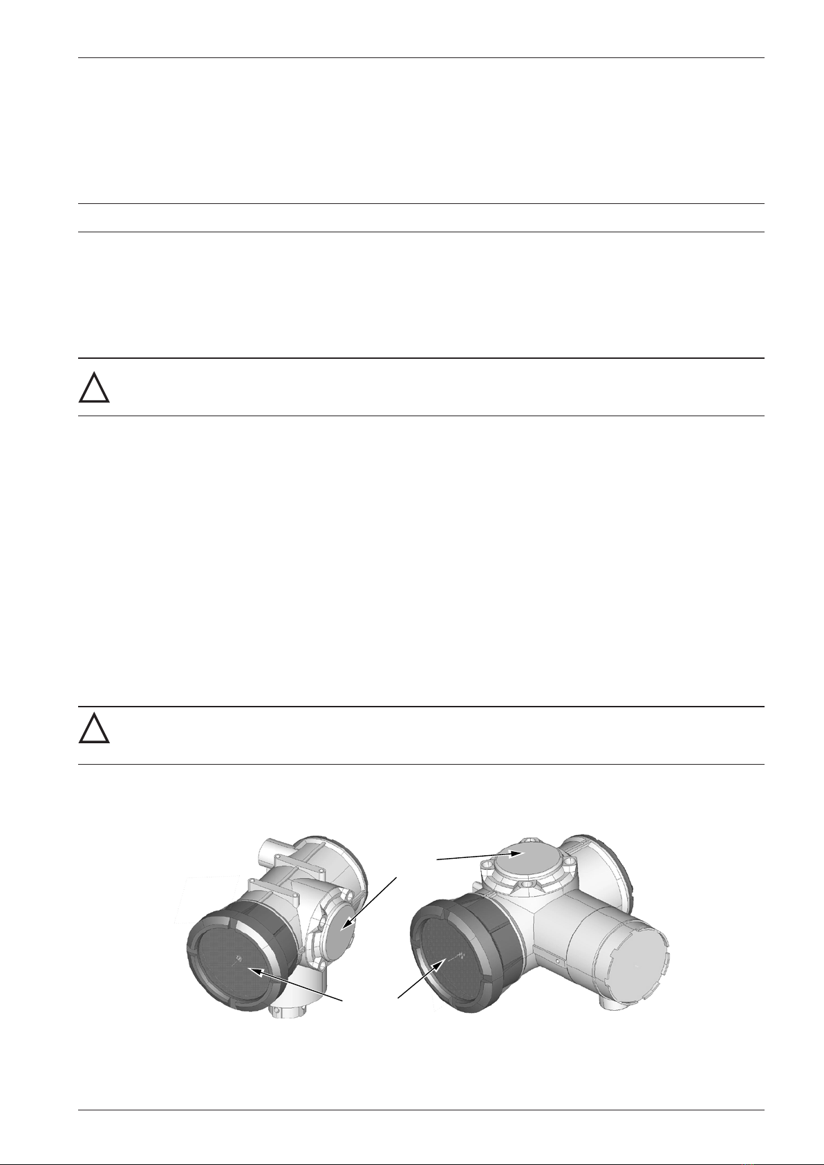
Sensor
As shown in Figure 1.1, the serial tag on the CT Series CC006 to CC080 sensor body is located on the front. Tag placement
may vary depending on sensor type.
Figure 1.1—Sensor tag location and sample serial tag
Transmitter
As shown Figure 1.2, the serial tag is located on the side of transmitter. Tag content will vary depending upon the certica-
tion standard selected when you placed your order.
CC Sensor Series Type PA0K C1 2 Ex d ib IIC T4 Gb
CP Sensor Series Type PA0K C1 2 Ex d ib IIB T4 Gb
Type PA0K C1 2 Ex d [ib] IIC T6 Gb
CERT. No.
DEKRA 11ATEX 0171X
IECEx DEK 12.0053X
MANUFACTURED BY OVAL CORPORATION
1-9-5, FUKUURA, KANAZAWA-KU,YOKOHAMA, KANAGAWA, 236-8645, JAPAN
II 2G 0344
HOUSTON, TX (USA)
RATING
POWER AC 85-250V 50/60hZ 29VA MAX.
DC 20-30V 6.9W MAX.
MAX. ALLOWED OUTPUT VOLTAGE: Um= 250V
ALLOWED FLUID TEMP.: -40°C TO +80°C
-40°C TO +70°C (CP015)
AMBIENT TEMP: -40°C ≤Ta ≤ 55°C
WARNING
DO NOT MODIFY OR ALTER COMPONENTS OR WIRING OF THE DEVICE
SEE MANUAL 50283755 FOR THE DETAILS OF ARRANGEMENT AND WIRING.
DO NOT OPEN WHEN AN EXPLOSIVE ATMOSPHERE IS PRESENT.
Figure 1.2—Transmitter tag location and sample serial tag
CamCor™ Coriolis Flow Meter Sensor
CC Sensor Series
Ex ib IIC T* Gb
CP Sensor Series
Ex ib IIB T* Gb
RATING
IS CIRCUIT
DRIVE CIRCUIT: 12.3V, 0.878A, 2.7W, 0µF
OTHER CIRCUITS: 15.0V, 17mA, 64mW, 0µF
SEE MANUAL 50283755 FOR Li VALUE OF
DRIVE CIRCUIT AND OTHER CIRCUITS.
CERT. No. DEKRA 11ATEX01/2
IECEx DEK 13.001
AMBIENT TEMP. RANGE: °C~ °C
PROCESS TEMP. RANGE: °C~ °C
“INTRINSICALLY SAFE”
“WARNING: SUBSTITUTION OF COMPONENTS MAY IMPAIR INTRINSIC SAFETY”
MANUFACTURED BY OVAL CORPORATION
1-9-5, FUKUURA, KANAZAWA-KU,YOKOHAMA, KANAGAWA, 236-8645, JAPAN
MODEL
SENSOR S/N
MAX. PRESS
TAG No.
DATE
TRANS. No.
PSI (MPa)
II 2G 0344
HOUSTON, TX (USA)

8
CamCor CT and PRO Series Hardware Manual Section 1
OPERATING CONDITIONS
In order to maintain the design metering accuracy and long service life, it is essential that the ratings, such as the ow rate,
pressure, and temperature, be held within the specied limits. These operating conditions are stated in Section 3—Speci-
cations and Performance (U.S. Customary Units), page 15 of this manual and in the product code section of the CamCor
CT Series and PRO Series General Specications. Before placing the meter into service, consider the following:
• If the process uid is corrosive, meter materials must be compatible.
• Cleanse the interior of ow tube thoroughly after measuring uids that deposit solids. A ow tube with solid deposits
can affect the meter accuracy.
• To change operating conditions, consult the factory.
• Some non-homogeneous gas-mixed ows are not measurable. Consult the factory for technical assistance in such ap-
plications.
INSTALLATION LOCATION
To ensure accurate and consistent measurement, the Coriolis ow meter should be installed in a location where pipeline
oscillation will not exceed 0.3G.
POWERING UP THE METER AFTER INSTALLATION
To ensure stable measuring conditions, allow a 20-minute warm-up period after installing . “WARM UP 20” will appear
and count down to zero after powering on the device. The number indicates remaining warm-up time in minutes.
STORAGE
If this product is to be stored for long periods of time before installation, take the following precautions:
1. Store your product in the manufacturer’s original packing used for shipping if possible.
2. Storage location should conform to the following requirements:
– Free from rain and water
– Free from vibration and impact shock
– At room temperature with minimal temperature and humidity variation
RETURNING EQUIPMENT
If the meter must be returned to Cameron for any reason, follow these steps to ensure the most efcient processing:
1. Clean the unit, ush out the tubes, and pack the sensor unit carefully. Provide complete information about the process
uid. Inadequate information will delay handling of the meter.
2. Fill in the forms on page 111 and page 112. Provide complete information about the material being returned,
including
– model number
– serial number
– reason for return
– return address
– full documentation of the process uid type
3. Pack the equipment carefully, using the original packaging if possible.
4. Return the complete ow meter, including the separate electronics unit, with all circuit boards and associated parts.
Important Remove the conduit connections and all other parts not originally shipped with the meter (i.e. wiring connections).
Important Completely remove foreign materials from the inner walls of the sensor unit. Because the sensor unit cannot be
disassembled, Cameron will not be able to remove buildup inside the tubes and service your meter.
CamCor CT and PRO Series Hardware Manual
9
Section 2
9
Section 2—Setup
Before moving the device to its intented location, perform the following tasks in a safe area.
EXAMINING THE DEVICE
Upon receipt,visually inspect the sensor and transmitter for any sign of damage that may have occurred during trASMEt.
Important If damage is observed, contact CAMERON for further instructions.
TRANSPORTATION
1. Transport the product to the installation site using the original manufacturer,s packing whenever possible.
2. Avoid impact shocks, rain and water during transportation.
POWER TEST
!
WARNING: Before attempting any wiring, ensure that all power is disconnected. Failure to disconnect main
service power to the device can cause severe personal injury, death, or substantial property damage. Before
reapplying power, ensure that all wiring connections are secure and connected properly.
Ensure that the device is receiving power using the following steps:
1. Wire power to the device using the detailed instructions provided in Power and Output Signal Connections (Integrally-
and Separately-mounted Transmitter Models), page 55.
2. To conrm that power is connected properly, turn on the device and verify that the backlight and green LED light up.
3. Power down the unit.
BAUD RATE FOR OPTIONAL COMMUNICATIONS
CamCor meters with optional communications are shipped ready to be wired. Communication wiring must be custom-
er-provided. See Line Wiring of Optional Communications, page 58 for wire sizes and additional information.
Using the Default Baud Rate
A CamCor meter purchased with the Modbus communication option is shipped with the baud rate set to 9600. To use the
device with this baud rate,
1. Ensure that power to the unit is turned off.
! WARNING: Failure to turn off power to the device can cause severe personal injury, death, or substantial
property damage. Before reapplying power, ensure that all wiring connections are secure and connected
properly.
2. Remove terminal cover B as follows:
Terminal
Cover B
Front Cover
INTEGRALLY-MOUNTED SEPARATELY-MOUNTED
Figure 2.1—Terminal cover B location on integrally-mounted and separately-mounted transmitter
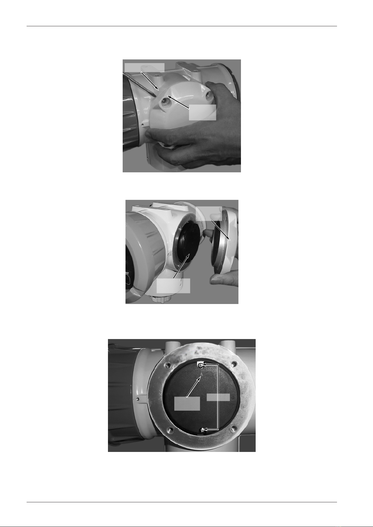
a. Locate terminal cover B (Figure 2.1) and unscrew and remove the four M8 hex bolts. Set bolts aside for
reassembly.
10
CamCor CT and PRO Series Hardware Manual Section 2
10
b. Insert a athead screwdriver between terminal cover B and the device body and gently pry off the terminal cover
(Figure 2.2, page 10), being careful not to damage the socket and spigot joint.
Terminal
Cover B
Device Body
Figure 2.2—Terminal cover B being separated from device body
c. Lift terminal cover B off to expose the black plastic cap (Figure 2.3).
Terminal
Cover B
Black
Plastic Cap
Figure 2.3—Black plastic cap located underneath Terminal cover B
d. Unscrew and remove the two M3×10mm screws holding the black plastic cap in place (Figure 2.4). Set screws
aside for reassembly.
Position
Arrow
Screws
Figure 2.4—Black plastic cap, detail view

11
Section 3 CamCor CT and PRO Series Hardware Manual
3. Lift off the black plastic cap to expose the maintenance board (Figure 2.5). Take care not to lose the spacers between
the circuit boards.
CAUTION The screws holding the plastic cap in place also secure two shock-absorbing spacers positioned be-
tween the maintenance board and the blind board underneath it (Figure 2.5). To avoid damage to the
circuit boards, ensure that the spacers are in place before reinstalling the black plastic cap.
Maintenance
Board
Spacer
Blind Board
Figure 2.5—Maintenance and blind boards, showing location of shock-absorbing spacer (1 of 2)
4. To retain the spacers in the proper position, insert the screws from the black plastic cap into the screw holes on the
Maintenance/Blind board assembly. Do not lift the board assembly from the enclosure.
Figure 2.6—Maintenance board, showing switch and terminal block positions
5. Verify that SW1 (Figure 2.6), which provides power to the maintenance board, is in the “P_ON” position.

12
CamCor CT and PRO Series Hardware Manual Section 3
6. Check the position of SW2 (Figure 2.6, page 11) and wire the cable as described below:
– If the switch is in the “IN” (default) position, wire the cable to the I/O board using the procedures described in
Line Wiring of Optional Communications, page 58.
– If the switch is in the “OUT” position, wire the cable to the TB30 terminal block located on the Maintenance
board.
7. Turn on power to the device.
8. Send a test message to the slave device using Modbus or HART communications. If using Modbus communications,
you must rst connect to the slave device. See Setting Modbus Slave Addresses, page 12 for detailed procedures.
9. Once communications are veried, turn off power to the device.
10. Replace the black plastic cap, ensuring that the position arrow is pointing up (Figure 2.4, page 10) and secure with
the fasteners removed in Step 2d.
11. Replace terminal cover B and secure them with the fasteners removed in Step 2a.
Changing the Baud Rate
The baud rate is adjustable using Switch 3 (SW3) on the Maintenance board located in the transmitter body. To change the
baud rate,
1. Turn off power to the device and access the Maintenance board using Steps 1 through 3 of “Using the Default Baud
Rate.”
2. Locate SW3 on the Maintenance board (Figure 2.6, page 11) and change the SW3-1 and SW3-2 positions (Figure
2.7) to set the desired baud rate. See the Baud Rate Switch Settings table below for switch positions.
Note Switches 3-3 (SW3-3) and 3-4 (SW3-4) are not required for Modbus communications.
Figure 2.7—Closeup of SW3, showing the baud rate set to 38400
BAUD RATE SWITCH SETTINGS
Baud Rate SW3-1 Setting SW3-2 Setting
9600 Off Off
19200 On Off
38400 Off On
Do Not Set On On
3. Follow Steps 7 through 11 of Using the Default Baud Rate procedure above.
SETTING MODBUS SLAVE ADDRESSES
Slave addresses can range from 1 to 255. Slave Address “0” broadcasts messages to all slave devices and is only available
for Modbus Function Code 16. If the broadcast message contains valid data, the device is updated and no response is sent
to the host system.
If you do not know the slave address of a device to be connected to the CamCor meter, you can set/reset it using the follow-
ing procedure:
WARNING Do not use this query while more than one slave is connected. In a multipoint drop connection
setup, all connected slaves share the same address; therefore, resetting the slave address will
assign the same address to all slave devices.

13
Section 3 CamCor CT and PRO Series Hardware Manual
1. Establish a point-to-point connection between the slave device and the CamCor meter.
2. Send the following message to the slave device using hexadecimal:
– Broadcast Slave Address: 0 (broadcast message)
– Function Code: 16 (write command)
– Register: 167 (slave address register)
– Write Quantity: 1
– Slave Address to Be Set: 1 to 255
3. Verify communications with the slave device by sending the following message:
– Slave Address established above: 1 to 255
– Register: 167 (slave address register)
– Function Code: 3 (read command)
– Write Quantity: 1
You should receive a valid response if communications have been successfully established. If you do not, repeat Steps 2
and 3.
Note Record slave addresses in a secure location. If you lose a slave address, repeat this procedure to reset it.

14
CamCor CT and PRO Series Hardware Manual Section 3
This page is left blank intentionally.

15
Section 3 CamCor CT and PRO Series Hardware Manual
Section 3—Specications and Performance (U.S. Customary
Units)
This section presents specications in U.S. Customary units. For specications in metric units, see Appendix A—CamCor
Specications (Metric Units), page A-1.
CT SERIES SENSOR GENERAL SPECIFICATIONS
Low-Flow Models (CC00A, CC001 and CC003)
Item Description
Model CC00A CC001 CC003
Nominal size 1/4" 10 mm, 1/2″, DN15
Materials Wetted parts SUS316L SUS316L, Alloy C22
Housing SUS304
O-rings Fluoro-elastomer (standard Viton®), PTFE (option) —
Process connection 1/4-18 FNPT ASME 100, 300, 600, 900 RF;
DIN PN 10, 16, 25, 40 RF ,
IDF Ferrule , Threaded
Applicable fluid Liquid and gas
Density range 0 to 2.0 g/mL
Temperature range −328°F to 392°F
Tube withstand @ 100°F—Wetted parts materials: SUS316L maximum 1440 psig;
Alloy C22 maximum 2185 psig
(depending on flange rating)
Maximum operating
pressure @ 100°F
Liquid 2176 psi
Gas 142 psig
Sensor housing withstand — 1044 psig
Flow direction Bi-directional
Explosion-proof configuration CSA, ATEX, and IECEx (Refer to Section 10—Explosion-proof Specifications, page 113 for details.)
Dust-tight, waterproof configuration IP66/67
1. When SUS316L is selected as the wetted parts material, the ange material will be dual-rated SUS316/SUS316L.
2. ASME 900 anges are only available in Alloy C22 material.
3. DIN anges are only available for meter material SUS316L.
4. For application with foods, this product does not comply with CE marking.
5. This pressure does not represent the rated test pressure of a pressure vessel. It represents 1/4 of the factory-tested breakdown pressure or the data obtained from FEA
analysis, whichever is lower. Distorted enclosures do not constitute a failure of the test.
6. Refer to “Explosion-proof Specications” on page 11 for details. In case of non-explosion-proof type, the maximum measurement temperature is 266°F. However, the
product must be used within the maximum ambient temperature of 113°F. Higher temperature limits can be achieved with the high-temperature models.
* Only available with separately-mounted transmitter and interconnect cable (ordered separately;10-meter minimum, available in 5-meter increments thereafter).
* For products conforming to the high-pressure gas safety regulations and CE marking, consult Cameron.
Standard Models (CC006 through CC080)
Item Description
Model CC006 CC010 CC015 CC025 CC040 CC050 CC080
Nominal size 10 mm, 1/2",
DN15
15 mm, 1/2˝,
DN15
25 mm, 1˝,
DN25
40 mm, 1-1/2˝,
DN40
50 mm, 2˝,
DN50
80 mm, 3˝,
DN80
Materials Wetted parts SUS316L, Alloy C22
Housing SUS304
Process connection ASME 150, 300, 600, 900 RF; DIN PN 10, 16, 25, 40 RF ; IDF Ferrule ; Threaded
Applicable fluids Liquid and gas
Density range 0 to 2.0 g/mL
Temperature range −328°F to 392°F
Tube withstand @ 100°FSUS316L: 1520 psig; Alloy C22: 2276 psig
Maximum operating pressure Depends on flange rating
Sensor housing withstand 551 psig 435 psig 319 psig 232 psig 261 psig 203 psig
Flow direction Bi-directional
Explosion-proof configuration CSA, ATEX, and IECEx (Refer to Section 10—Explosion-proof Specifications, page 113 for details.)
Dust-tight, waterproof configuration IP66/67
1. When SUS316L is selected as the wetted parts material, the ange material will be dual-rated SUS316/SUS316L.
2. ASME 900 anges are only available in Alloy C22 material.
3. DIN anges are only available for meter material SUS316L.
4. For application with foods, this product does not comply with CE marking.
5. This pressure does not represent the rated test pressure of a pressure vessel. It represents 1/4 of the factory-tested breakdown pressure or the data obtained from FEA
analysis, whichever is lower. Distorted enclosures do not constitute a failure of the test.
6. Refer to Section 10—Explosion-proof Specications, page 113 for details. In case of non-explosion-proof type, the maximum measurement temperature is 266°F. Howev-
er, the product must be used within the maximum ambient temperature of 113°F. Higher temperature limits can be achieved with the high-temperature models.
* Available with either integrally-mounted or separately-mounted transmitter.
* For products conforming to the high-pressure gas safety regulations and CE marking, consult Cameron.

16
CamCor CT and PRO Series Hardware Manual Section 3
High-Flow Models (CC100 through CC250)
Item Description
Model CC100 CC150 CC15H CC200 CC20H CC250
Nominal size 100 mm, 4″, DN100 150 mm, 6″, DN150 200 mm, 8″, DN200 250 mm, 10″, DN250
Materials Wetted parts SUS316L
Housing SUS304
Process connection ASME 150, 300, 600 RF; DIN PN 10, 16, 25, 40 RF
Applicable fluids Liquid
Density range 0.3 to 2.0 g/mL
Viscosity range Maximum 10000 cP
Temperature range –328°F to 392°F
Tube withstand @ 100°F1924 psig 1551 psig 1300 psig
Maximum operating pressure Depends on flange rating
Flow direction Bidirectional
Explosion-proof configuration CSA, ATEX, and IECEx (Refer to Section 10—Explosion-proof Specifications, page 113 for details.)
Dust-tight, waterproof configuration IP66/67
1. When SUS316L is selected as the wetted parts material, the ange material will be dual-rated SUS316/SUS316L.
2. Models CC20H and CC250 available only up to ASME Class 300 anges.
3. Refer to Section 10—Explosion-proof Specications, page 113 for details. When owing non-combustible product, the maximum media temperature is 266°F. However,
the maximum ambient temperature is 113°F. Higher temperature limits can be achieved with the high-temperature models. For products conforming to the high-pressure
gas safety regulations, consult Cameron.
High-Pressure Models (CC010 and CC015)
Item Description
Model CC010 CC015
Materials Wetted parts Flow Tube: Alloy C22; Manifold: Alloy C22 equivalent (CX2MW)
Housing SUS304
Process connection 3/8-18 FNPT 3/4-14 FNPT
Applicable fluid Liquid and gas
Density range 0.3 to 2.0 g/mL
Temperature range Integrally-mounted: –4°F to 194°F; Separately-mounted: –328°F to 392°F
Maximum operating pressure @ 68°F5221 psig 6237 psig
Sensor housing withstand 435 psig 319 psig
Flow direction Bidirectional
Explosion-proof configuration CSA, ATEX, and IECEx (Refer to Section 10—Explosion-proof Specifications, page 113 for details.)
Dust-tight, waterproof configuration IP66/67
1. This pressure does not represent the rated test pressure of a pressure vessel. It represents 1/4 of the factory-tested breakdown pressure or the data obtained from FEA
analysis, whichever is lower. Distorted enclosures do not constitute a failure of the test. For products conforming to the high-pressure gas safety regulations and CE mark-
ing, consult Cameron.
High-Temperature Models (CC025 through CC150)
Item Description
Model CC025 CC040 CC050 CC080 CC100 CC150
Nominal size 25 mm, 1˝,
DN25
40 mm, 1-1/2˝,
DN40
50 mm, 2˝,
DN50
80 mm, 3˝,
DN80
100 mm, 4˝,
DN100
150 mm, 6˝,
DN150
Materials Wetted parts SUS316L SUS316L, Alloy C22 SUS316L
Housing SUS304
Process connection 1" to 3": ASME 150, 300, 600, 900 RF; DIN PN 10, 16, 25, 40 RF
4" and 6" : ASME 150, 300, 600 RF; DIN PN 10, 16, 25, 40 RF
Applicable fluids Liquid
Density range 0.3 to 2.0 g/mL
Temperature range –40°F to 662°F
Tube withstand @ 100˚F SUS316L: 1520 psig; Alloy C22 (Model CC080 only): 2276 psig 1924 psig
Maximum operating pressure Dependent on flange rating
Sensor housing withstand 232 psig 261 psig 203 psig —
Flow direction Bidirectional
Explosion-proof configuration CSA, ATEX, and IECEx (Refer to Section 10—Explosion-proof Specifications, page 113 for details.)
Dust-tight, waterproof configuration IP66/67
Optional Heat Tracer Specications (Available for Models CC025 through CC080)
Applicable fluids Hot water, saturated steam, overheated steam
Heat retention fluid maximum output pressure 142 psig
Joint port for heat retention fluid 10 mm stainless tubing
Recommended joint Standard stainless steel ferrule-type compression fitting for 10 mm tubing
1. When SUS316L is selected as the wetted parts material, the ange material will be dual-rated SUS316/SUS316L.
2. Allowable ambient temperature permitted for the sensor unit is up to 122°F.
3. This pressure does not represent the rated test pressure of a pressure vessel. It represents 1/4 of the factory-tested breakdown pressure or the data obtained from FEA
analysis, whichever is lower. Distorted enclosures do not constitute a failure of the test.
4. ASME 900 anges are only available in Alloy C22 material.
5. Heat trace should only be used for heating the meter. Do not use for cooling of owing media.
* For products conforming to the high-pressure gas safety regulations, consult Cameron.
* Only available with separately-located transmitter and interconnect cable (ordered separately; 10-meter minimum, available in 5-meter increments thereafter).

17
Section 3 CamCor CT and PRO Series Hardware Manual
Low-Temperature Models (CC025 through CC250)
Item Description
Model CC025 CC040 CC050 CC080 CC100 CC150 CC15H CC200 CC20H CC250
Nominal size
25 mm,
1˝,
DN25
40 mm,
1-1/2˝,
DN40
50 mm,
2˝,
DN50
80 mm,
3˝,
DN80
100 mm,
4˝,
DN100
150 mm,
6˝, DN150
200 mm,
8˝, DN200
250 mm,
10˝,
DN250
Materials Wetted parts SUS316L, Alloy C22 SUS316L
Housing SUS304
Process connection ASME 150, 300, 600, 900 RF;
DIN PN 10, 16, 25, 40 RF ; IDF Ferrule
ASME 150, 300, 600 RF;
DIN PN 10, 16, 25, 40 RF ASME 150, 300 RF;
DIN PN 10, 16, 25, 40 RF
Applicable fluids Liquid and gas Liquid
Density range 0.3 to 2.0 g/mL
Temperature range –328°F to 122°F
Tube withstand @ 100°F1520 psig 1924 psig 1551 psig 1300 psig
Maximum operating pressure Dependent on flange rating
Sensor housing withstand 232 psig 261 psig 203 psig —
Flow direction Bi-directional
Explosion-proof configuration CSA, ATEX, and IECEx (Refer to Section 10—Explosion-proof Specifications, page 113 for details.)
Dust-tight, waterproof configuration IP66/67
1. When SUS316L is selected as the wetted parts material, the ange material will be dual-rated SUS316/SUS316L.
2. DIN anges are only available for meter material SUS316L.
3. ASME 900 anges are only available in Alloy C22 material.
4. For application with foods, this product does not comply with CE marking.
5. This pressure does not represent the rated test pressure of a pressure vessel. It represents 1/4 of the factory-tested breakdown pressure or the data obtained from FEA
analysis, whichever is lower. Distorted enclosures do not constitute a failure of the test.
* Only available with separately-mounted transmitter and interconnect cable (ordered separately; 10-meter minimum, available in 5-meter increments thereafter).
* For products conforming to the high-pressure gas safety regulations and CE marking, consult Cameron.
PRO SERIES SENSOR GENERAL SPECIFICATIONS
Item Description
Model CP006 CP010 CP015 CP025 CP040 CP050
Nominal size (in.) 1/2 1/2 1/2 1 1-1/2 2
Materials Wetted parts SUS316L
Housing SUS304
Process connection ASME 150, 300, 600 RF; IDF Ferrule; Threaded (CP006, CP010 and CP015 only)
Applicable fluid Liquid
Density range 0.3 to 2.0 g/mL
Temperature range –40°F to 257°F
Maximum operating pressure Dependent on process connection
Flow direction Bidirectional
Explosion-proof configuration CSA, ATEX, and IECEx (Refer to Section 10—Explosion-proof Specifications, page 113 for details.)
Dust-tight, waterproof configuration IP66/67
1. Refer to Section 10—Explosion-proof Specications, page 113. In case of non-explosion-proof model, up to 257˚F is permitted. However, the product must be used within
the maximum ambient temperature of 113˚F.
2. Cleaning in place (CIP) is permitted within the temperature range.

18
CamCor CT and PRO Series Hardware Manual Section 3
TRANSMITTER GENERAL SPECIFICATIONS
Item Description
Model PA0K
Power supply CSA: 85 to 264 VAC, 50/60 Hz or 20 to 30 VDC (Safety rated 100 to 240 VAC, 50/60 Hz)
ATEX: 100 to 240 VAC, 50/60 Hz, or 20 to 30 VDC
Power consumption CSA: Maximum 15 W; ATEX: 250 V
Ambient temperature –40°F to 131°F
Transmission length (separately-mounted) Maximum 200 m (interconnect cable used)
Applicable EU directive EMC Directive: 2004/108/EC; ATEX Directive: 94/9/EC
Applicable EN standards EMC—EN 55011: 1998/A1, 1999/A2, 2002 Group 1, Class B; EN 61000-6-2: 2001; EN 061326-1: 2006
ATEX—EN 60079-0: 2012; EN 60079-1: 2007; EN 60079-11: 2012
IECEx—IEC 60079-0: 2011; IEC 60079-1: 2007-04; IEC 60079-11: 2011
Explosion-proof configuration CSA, ATEX, and IECEx (Refer to Section 10—Explosion-proof Specifications, page 113 for details.)
Dust-tight, waterproof configuration IP66/67
Transmitter configuration Integral or separately-mounted
Finish Paint type: Baked enamel; Paint color: Light gray (RAL7035)
Display LCD display provided (128×64 dots), backlit (white, orange) ; Two infrared light sensors; Two LEDs (green and red)
Weight (approximate) Integrally-mounted model, 7.94 lb; Separately-mounted model, 11.02 lb
Communication interface HART (Standard) Protocol Version 7, Bell 202
Modbus (Optional) RS-485: Baud rate: 9600, 19200, 38400;
RTU; Response time: 25 to 50 ms
Damping (default) Flow rate, 0.8 sec.; Density, 4.0 sec.; Temperature, 2.5 sec.
Low-flow cutoff (default) Less than 0.6% of maximum service flow rate
Pulse output
Open drain (equivalent to open collector)—10 V to 30 V, 50 mADC, ON resistance ≤0.6 Ω OR
Voltage—1.5 V maximum (low level) to 13 V minimum (high level), output impedance: 2.2 kΩ;
Frequency output range: 0 to 10000 Hz (Maximum: 11000 Hz)
Analog output 4 to 20 mADC (maximum load: 600 Ω);
Select two outputs from instant flow rate (mass or volume) temperature, and density.
Status output Open drain (equivalent to open collector)—30 V maximum, 50 mADC, ON resistance ≤0.6 Ω;
Select one from error (default) , flow direction, high/low alarm, or drive output alarm.
Status input Contact-closure (Form “a” contact)—Close: 200 Ω maximum, Open: 100 kΩ minimum;
Select one output from remote zero, total reset, 0% signal lock, or function off (default).
1. Below –4°F, the display loses its visibility due to weakened contrast. Both the display and infrared sensor may exhibit slow responses below –4°F.
2. If the sensor-to-transmitter communications cable length exceeds 200 m, consult Cameron.
3. HART communications are available only across the Analog Output 1.
4. The status output can also be congured to activate when meter zeroing is in process.
5. Electrical noise ltering components are installed in connections between power source, output, communications, and chassis.

19
Section 3 CamCor CT and PRO Series Hardware Manual
CT SERIES SENSOR GENERAL PERFORMANCE
Flow Rate
Meter type Model Size
(in.)
Guaranteed
minimum rate
(lb/min)
Minimum
setting rate
(lb/min)
Maximum
service rate
(lb/min)
Maximum
allowable rate
(lb/min)
Uncertainty Repeatability Zero
stability
(lb/min)
Analog
output
uncertainty
Liquids Gases Liquids Gases
Low-flow CC00A
1/4
0.00088 0.0044 0.088 0.132 ±0.2%
of reading
(±ZS)
±0.5%
of reading
(±ZS)
±0.05%
of reading
(±1/2 ZS)
±0.25%
of reading
(±1/2 ZS)
0.000013
Uncertainty
±0.1%
of full scale
CC001 0.0033 0.0165 0.33 0.496 0.00005
CC003 1/2 0.026 (0.033) 0.13 2.65 5.29 (6.61)
±0.1%
of reading
±0.05%
of reading
0.000066
CC006 1/2 0.132 0.66 13.23 26.46 0.00066
CC010 1/2 0.44 2.2 44.09 88.18 0.0022
CC015 1/2 1.32 6.61 132 265 0.0066
Standard
and Low-
temperature
CC025 1 3.97 19.8 397 794 0.0198
CC040 1-1/2 14.33 71.7 1433 2866 0.071
CC050 2
CC080 3 44.09 220 4409 8818 0.22
CC100 4 126 628 12566 25133
±0.1%
of reading
(±ZS)
—
±0.05%
of reading
(±1/2 ZS)
—
0.628
CC150 6
CC15H 6 257 1286 25721 51441 1.286
CC200 8
CC20H 8 514 2572 51441 102883 2.572
CC250 10
High-
pressure CC010 3/8 0.88 4.41 30.86 61.73 ±0.2%
of reading
(±ZS)
±0.5%
of reading
(±ZS)
±0.1%
of reading
(±1/2 ZS)
±0.25%
of reading
(±1/2 ZS)
0.0077
CC015 3/4 2.87 14.33 93.7 187 0.0234
High-
temperature
CC025 1 3.97 19.8 397 794
±0.1%
of reading
(±ZS)
—
±0.05%
of reading
(±1/2 ZS)
—
0.0396
CC040 1-1/2 14.33 71.7 1433 2866 0.143
CC050 2
CC080 3 44.09 220 4409 8818 0.441
CC100 4 126 628 12566 25133 1.257
CC150 6
1. When a maximum allowable range 6.61 lb/min is adopted, the minimum ow rate is 0.033 lb/min.
2. ±ZS is applied for ow rates below 5% ( 2.5% for Model CC003) of the maximum service rate (within the guaranteed ow range).
3. ±1/2 ZS is applied for ow rates below 5% (2.5% for Model CC003) of the maximum service rate (within the guaranteed ow range).
4. If an uncertainty of ±0.1% of reading is required, consult Cameron.
5. Above maximum service ow rate, the uncertainty is ±0.3% of reading (±ZS).
• If you request volume flow measurement for the purpose of fiscal transactions or weights and measurements transactions, contact Cameron.
• In gas measurement, the maximum permissible flow velocity varies with the type of gas and some may be beyond the bounds of measurement. If so, contact Cameron.
• ZS = Zero stability error
(During testing, zero stability and current flow rate should be read in the same measurement unit.)
Zero stability error = Zero stability
× 100%
Current flow rate
Volumetric Flow Rate Density (Liquids)
Model Units Guaranteed
minimum rate
Minimum
setting rate
Maximum
service rate
Maximum
allowable Meter type Model Size (in.) Metering
range Uncertainty Analog output
uncertainty
CC00A gal/hr 0.006 0.032 0.635 0.952 Low-flow CC00A
1/4
0.3 to 2g/mL
±0.003 g/mL
Uncertainty
±0.1%
of full scale
CC001 gal/hr 0.023 0.119 2.38 3.57 CC001
CC003 gal/hr 0.19 0.952 19.04 38.07 CC003 1/2
±0.0005 g/mL
CC006 gal/min 0.016 0.08 1.58 3.17 CC006 1/2
CC010 gal/min 0.053 0.264 5.28 10.6 CC010 1/2
CC015 gal/min 0.159 0.793 11.5 31.7 CC015 1/2
CC025 gal/min 0.476 2.38 47.6 95.2 Standard
and Low-
temperature
CC025 1
CC040 gal/min
1.72 8.59 172 344
CC040 1-1/2
CC050 gal/min CC050 2
CC080 bbl/hr 7.55 37.8 755 1511 CC080 3
CC100 bbl/hr
21.5 108 2153 4306
CC100 4
CC150 bbl/hr CC150 6
CC15H bbl/hr
44.1 220 4407 8813
CC15H 6
CC200 bbl/hr CC200 8
CC20H bbl/hr
88.1 441 8813 17627
CC20H 8
CC250 bbl/hr CC250 10
CC010* gal/min 0.106 0.529 3.7 7.4 High-
pressure
CC010 3/8
0.3 to 2 g/mL ±0.004 g/mL
Uncertainty
±0.1%
of full scale
CC015* gal/min 0.344 1.719 11.2 22.5 CC015 3/4
* High-pressure models
1. Calculations based on water (specic gravity of 1) at 59°F (mass = 62.37
lb/ft3). Actual ow ranges vary with media density. To determine the ow
range for your uid, divide the values above by the uid's specic gravity.
High-
temperature
CC025 1
0.3 to 2g/mL ±0.003g/mL
CC040 1-1/2
CC050 2
CC080 3
CC100 4
CC150 6
20
CamCor CT and PRO Series Hardware Manual Section 3
PRO SERIES SENSOR GENERAL PERFORMANCE
Mass Flow Rate
Item Description
Model CP006 CP010 CP015 CP025 CP040 CP050
Flow rate
Guaranteed minimum rate (lb/min) 0.88 2.82 7.05 21.2 70.5 70.5
Minimum setting rate (lb/min) 2.2 7.05 17.6 52.9 176 176
Maximum service rate (lb/min) 22 70.5 176 529 1764 1764
Maximum allowable rate (lb/min) 44.1 141 353 1058 3527 3527
Uncertainty ±0.2% of reading (± zero stability)
Repeatability ±0.1% of reading (± 1/2 zero stability)
Zero stability (lb/min) 0.0033 0.011 0.026 0.079 0.265 0.265
Density
(Liquid)
Metering range 0.3 to 2 g/mL
Uncertainty ±0.003 g/mL
Analog output uncertainty ±0.1% of full scale
During testing, zero stability and flow rate during the test should read in the same measurement unit.
Zero stability error = Zero stability × 100%
Current flow rate
Volumetric Flow Rate
Item Description
Model CP006 CP010 CP015 CP025 CP040 CP050
Guaranteed minimum rate (gal/min) 0.106 0.338 0.846 2.54 8.46 8.46
Minimum setting rate (gal/min) 0.264 0.846 2.12 6.35 21.2 21.2
Maximum service rate (gal/min) 2.64 8.46 21.2 63.5 212 212
Maximum allowable rate (gal/min) 5.29 16.9 42.3 127 423 423
1. Calculations based on water (specic gravity of 1) at 59°F (mass = 62.37 lb/ft3). Actual ow ranges vary with media density. To determine the ow range for your uid,
divide the values above by the uid’s specic gravity.
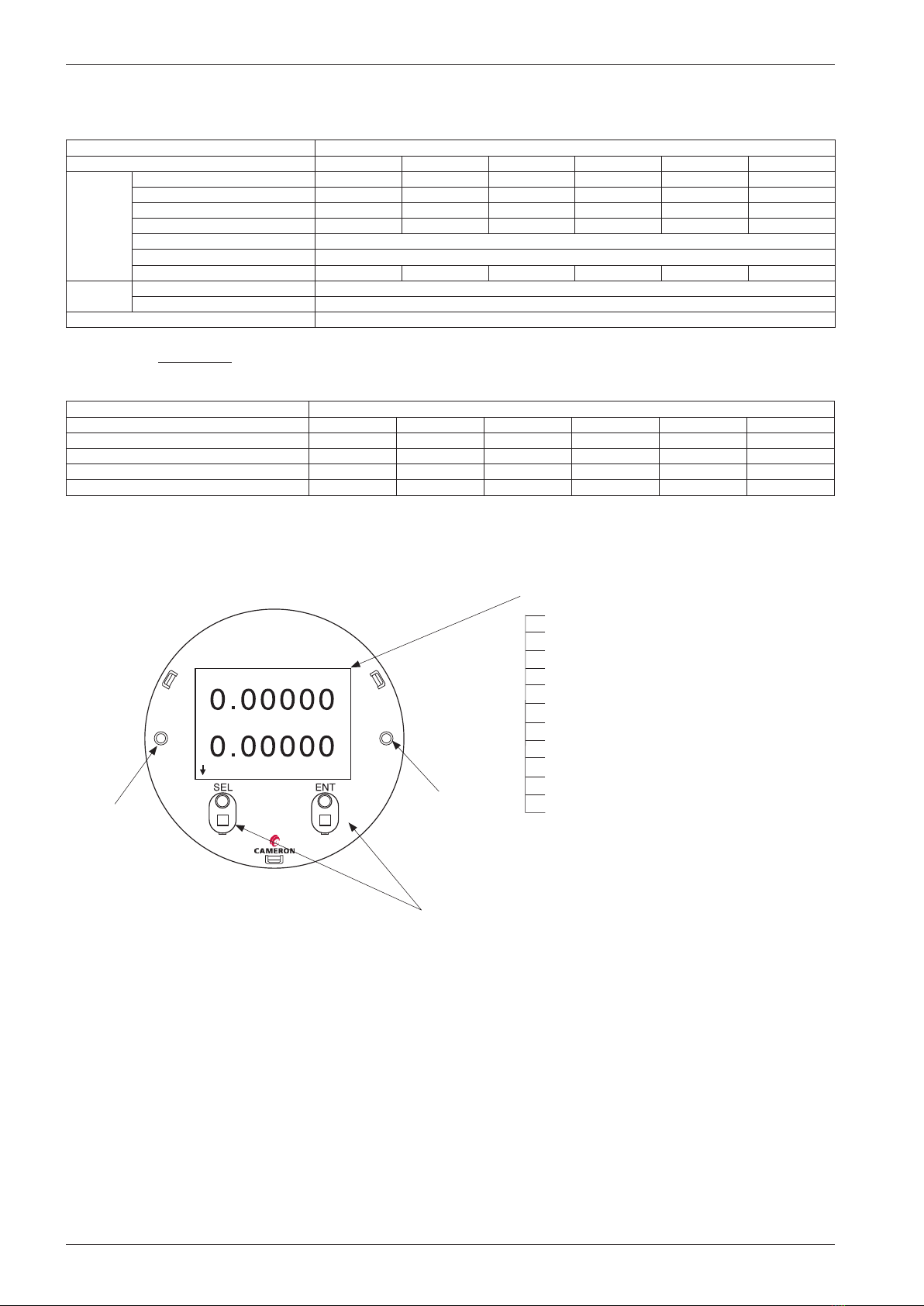
DISPLAY
lb/min
gal/min
Mass Flow
Vol Flow
CamCor
Coriolis Flow Meter
1. Mass instant flow rate
2. Volume instant flow rate
3. Density
4. Temperature
5. Pulse count 1 (mass or volume)
6. Pulse count 2 (mass or volume)
7. Total 1 (mass or volume)
8. Total 2 (mass or volume)
9. Analog 1 (% instant)
10. Analog 2 (% instant)
11. Status information
12. Mode select (parameter setup)
LED (Green)
LED (Red)
To select the mode, touch and hold your nger over the front glass
where the infrared optical sensor appears.
Display modes
• LCD backlight available in white and orange. Color
changes according to the status of ow meter.
• In most cases, the backlight shuts off automatically
if the optical sensor does not respond within a user-
dened duration.
This manual suits for next models
22
Table of contents
Other Sensia Measuring Instrument manuals

Sensia
Sensia CALDON LEFM CheckPlus-C User manual

Sensia
Sensia NUFLO MC-I User manual

Sensia
Sensia NUFLO MC-III User manual

Sensia
Sensia NUFLO TMP-100 User manual

Sensia
Sensia Barton 7000 Series User manual

Sensia
Sensia NuFlo Scanner 2000 Instructions for use

Sensia
Sensia CamCor User manual

Sensia
Sensia LEFM 2010FE User manual

Sensia
Sensia NuFlo User manual

Sensia
Sensia CALDON SVM 389Ci User manual


