manuals.online logo
Brands
  1. Home
  2. •
  3. Brands
  4. •
  5. SENSIRION
  6. •
  7. Accessories
  8. •
  9. SENSIRION LD20 Series Installation guide

SENSIRION LD20 Series Installation guide

www.sensirion.com Version 1,
D1 1/4
Engineering Guidelines
LD20 Base Station
Connector Block for Electrical Contact
Preface
The LD20 base station has been designed as an
easy-to-use tool for evaluating the LD20 liquid flow
sensor. The connector block performs two main
tasks: it mechanically fixates the sensor in place via
a clip-in mechanism and provides a simple electrical
interface between the contact pads of the sensor and
a PC or any other system for first bench-top tests.
Sensirion’s base station is 3D-printed from Polyamid
and thus has to be handled with care.
The base station can be anchored to a test bench
using the integrated mounting holes.
The male M8 electrical connector is compatible with
Sensirion’s SCC1 sensor cables.
Basic ESD protection is implemented as well.
The 3D-printed part is designed for testing purposes
only and will not be commercially available except as
part of the LD20 Evaluation Kit. Customers are
expected to refine the mechanical and electrical
interfaces to best suit their application needs within
their own base station design..
1Using the Sensirion LD20 Base Station
Please follow the steps below in using and handling the LD20 base station:
Connection:
Make sure all parts are clean and free of debris.
Check for the proper alignment of the LD20 sensor (1) : the orientation is correct if the contact pads of the flow
sensors are located on top of the spring pins and if the triangular recess of the LD20 sensor fits to the counterpart
on the base station. Press the LD20 flow sensor down into the base station (2).
All three versions of the LD20 series fit into the LD20 base station.
Connect the base station’s male M8 with the SCC1-USB sensor cable for a plug-and-play connection with a PC.
You can connect any of Sensirion’s SCC1 sensor cables as well, if you want to use analog voltage output signals
or RS485.
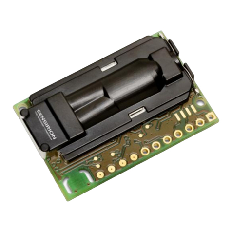
Figure 1: Proper alignment of the LD20 sensor to the Sensirion base station
www.sensirion.com Version 1, D1 2/4
Disconnection:
To disconnect the sensor after testing, hold the base station in one hand and slightly press the clip backwards
with the other hand. The sensor will snap out.
Handling and cleaning:
The 3D-printed LD20 base station needs to be handled with proper care. Especially the clip is sensitive and could
break off if too much force is applied, while disconnecting or connecting the sensor.
There is no fluidic sealing between sensor and base station. Thus prevent liquids from spilling onto the sensor
when clipped into the base station.
Because of the electronics and its housing material, the base station can’t be gamma sterilized or autoclaved.
Contact Sensirion in case of further questions about possibilities to clean the base station.
2Electronic Specifications of the Sensirion LD20 Base Station
The pin assignment of the LD20 sensor is shown in Figure 2. The signals are fed to a male connector at the base station
(type M8, 4-pin, threaded lock according to IEC 61076-2-101 (Ed. 1)/ IEC 60947-5-2), which is compatible with all of
Sensirion’s SCC1 sensor cables. See Figure 3 for the pin-out of the M8 connector.
Pad
Electrical pad layout
1
SDA (data)
2
SCL (clock)
3
VDDD
4
VDDA
5
GND
Pad
Electrical pinout M8
1
SDA (data)
2
GND
3
VDD
4
SCL (clock)
Digital communication between a master and the LD20 sensor (= slave) runs via the standard I²C-interface. The physical
interface consists of two bus lines, a data line (SDA) and a clock line (SCL) which need to be connected via pull-up resistors
to the bus voltage of the system. By default, the I2C address is set to 64 (hexadecimal: 40, binary: 1000000). These lines
can be used on the 3.3 V level with a clock frequency of 100 kHz.
Parameter
Min.
Typ.
Max.
Units
I2C Bus Clock Frequency
100
kHz
Output Voltage Low
(SDA/SCL), Isink = 6 mA
0.1
0.5
V
Low Level Output Current
(SDA/SCL)
6
mA
High Level Input Voltage
(SDA/SCL)
2.0
V
Low Level Input Voltage
(SDA/SCL)
1.0
V
Table 3: I²C output characteristics
For the detailed specifications of the I²C communication, please refer to the specific I²C Application Notes from Sensirion.
Figure 2: Pin assignment of the LD20 sensor.
Figure 3: Pinout at the connector side of the male M8 connector being part of the LD20 base station.
1… 5
www.sensirion.com Version 1, D1 3/4
3Engineering Guidelines for your LD20 Connector Block
Sensirion’s LD20 base station is meant for testing purposes only, not for design-in. Thus, customers are expected to design
their own LD20 connector block. The following engineering guidelines are provided for reference.
Mechanical layout:
In general, the recommendation for the mechanical layout of the customized LD20 connector block is to use only the
middle part of the plastic body for fixation and alignment purposes (see colored surfaces in Figure 4). Therefore, the outer
dimensions of these surfaces are the same for all versions of the LD20 series independent of flow rate ranges or chosen
fluidic fittings. This enables an easy exchange of the different LD20 versions while using the same connector block.
Figure 5 provides an overview of the layout dimensions of the LD20 series needed for a mechanical design-in (here
exemplarily for the LD20-2600B with barbed fittings).
Figure 4: LD20 surfaces (green) to be used for fixation and alignment purposes.
Figure 5: Layout drawing of the mechanical dimension of the LD20-2600B sensor.
www.sensirion.com Version 1, D1 4/4
Electronic circuit:
The following section describes the recommended way to electrically contact the LD20 sensor itself. Currently an electronic
circuitry is built into Sensirion’s base station in order to stabilize the output signals, to have some ESD protection, and to
provide a supply voltage buffer (see Figure 6). The resistors R3 and R4 drawn in grey are to be used as pull-up resistors
for the I2C interface. Typical resistances are 2.2 kΩto 10 kΩ, depending on I2C bus capacitance and communication
speed.
Order information for the spring pins used in the base station design from Sensirion:
Manufacturer: Preci Dip
Manufacturer part number: 821-S1-005-30-012101
Digikey part number: 1212-1735-ND
Lead times might be several weeks.
Copyright© 2016, SENSIRION.
CMOSens® is a trademark of Sensirion.
All rights reserved.
Headquarters and Subsidiaries
SENSIRION AG
Laubisruetistr. 50
CH-8712 Staefa ZH
Switzerland
phone: +41 44 306 40 00
fax: +41 44 306 40 30
[email protected]m
www.sensirion.com
Sensirion Inc., USA
phone: +1 805 409 4900
[email protected]
www.sensirion.com
Sensirion Japan Co. Ltd.
phone: +81 3 3444 4940
info-jp@sensirion.com
www.sensirion.co.jp
Sensirion Korea Co. Ltd.
phone: +82 31 337 7700-3
info-kr@sensirion.com
www.sensirion.co.kr
Sensirion China Co. Ltd.
phone: +86 755 8252 1501
info-cn@sensirion.com
www.sensirion.com.cn
Sensirion Taiwan Co. Ltd.
[email protected]m
www.sensirion.com
To find your local representative, please visit www.sensirion.com/contact
Figure 6: Recommended electronic circuitry of the LD20 connector block.

Other SENSIRION Accessories manuals

SENSIRION SCD4 Series User manual

SENSIRION

SENSIRION SCD4 Series User manual

SENSIRION SCD42 User manual

SENSIRION

SENSIRION SCD42 User manual

SENSIRION EK-P3 User manual

SENSIRION

SENSIRION EK-P3 User manual

SENSIRION SCD40-D-R2 User manual

SENSIRION

SENSIRION SCD40-D-R2 User manual

SENSIRION SEN5 Series User manual

SENSIRION

SENSIRION SEN5 Series User manual

SENSIRION SCD30 User manual

SENSIRION

SENSIRION SCD30 User manual

SENSIRION SCD4x User manual

SENSIRION

SENSIRION SCD4x User manual

SENSIRION SCD30 User manual

SENSIRION

SENSIRION SCD30 User manual

SENSIRION SHT4x User manual

SENSIRION

SENSIRION SHT4x User manual

SENSIRION SDP600 Series User manual

SENSIRION

SENSIRION SDP600 Series User manual

SENSIRION SCD4 Series User manual

SENSIRION

SENSIRION SCD4 Series User manual

Popular Accessories manuals by other brands

Elsat iNode:0x0809 instruction manual

Elsat

Elsat iNode:0x0809 instruction manual

TankScan TSU1000M Setup instructions

TankScan

TankScan TSU1000M Setup instructions

NEVADANANO MPS user manual

NEVADANANO

NEVADANANO MPS user manual

SICK safeVisionary2 operating instructions

SICK

SICK safeVisionary2 operating instructions

Sentec OxiVenT OV-N Directions for use

Sentec

Sentec OxiVenT OV-N Directions for use

Pepperl+Fuchs OIT500-F113-B17-CB manual

Pepperl+Fuchs

Pepperl+Fuchs OIT500-F113-B17-CB manual

Emos P5728 manual

Emos

Emos P5728 manual

Technics SH-TB10-S operating instructions

Technics

Technics SH-TB10-S operating instructions

INNOBIZ 2141 Instructions for use

INNOBIZ

INNOBIZ 2141 Instructions for use

Cresta KTS 101 quick start guide

Cresta

Cresta KTS 101 quick start guide

iDo Seven D manual

iDo

iDo Seven D manual

PASCO PASPORT PS-2177 instruction sheet

PASCO

PASCO PASPORT PS-2177 instruction sheet

Elseta IOMOD HT user manual

Elseta

Elseta IOMOD HT user manual

Balluff BTL7-S5 B-M Series Condensed guide

Balluff

Balluff BTL7-S5 B-M Series Condensed guide

Lowrance LMF-200 Installation and operation instructions

Lowrance

Lowrance LMF-200 Installation and operation instructions

EVE Motion 20EAK9901 Get started

EVE

EVE Motion 20EAK9901 Get started

IFM efector200 OOF Series operating instructions

IFM

IFM efector200 OOF Series operating instructions

PCB Piezotronics M132A31 Installation and operating manual

PCB Piezotronics

PCB Piezotronics M132A31 Installation and operating manual

manuals.online logo
manuals.online logoBrands
  • About & Mission
  • Contact us
  • Privacy Policy
  • Terms and Conditions

Copyright 2025 Manuals.Online. All Rights Reserved.