SETTING
All sensor settings can be configured, in individual or group basis, by an OS-NET
Remote Programmer SRP-281. Following table highlights the setting items and options
available with ON-LRD-209S. For detailed setting operation, please refer to the OS-NET
Programming Guide available for download from www.irtec.com.
CONTROL SCHEME
The ON-LRD-209S series can be programmed to control the connected lighting in one of the schemes as below.
SETTING ACKNOWLEDGEMENT
The sensor will acknowledge setting success or failure with different indications by device LED or connected lighting.
INDICATION ACKNOWLEDGEMENT REMARKS
Device LED fast blinking in GREEN and BLUE. The device isscanning and linking to the network. The fast blinking (on-off per 0.2 second)
only appears during network linking.
Device LED blinks twice every 2-second in
GREEN or BLUE.
The sensor detects occupant’s motion. GREEN means the device is network linked.
BLUE means the device is unlinked.
Device LED blinks twice every 2-second for
5 minutes, and then 15-second after power
applied.
The device is set with daylight sensing control.
(DSVM or DSC)
GREEN means the device is network linked.
BLUE means the device is unlinked.
Device short beeps twice.
Receiving a single setting or control command.
Device beeps one long and two short. The
connected lights flash twice.
1. Multiple setting data UPLOAD successful.
2. GROUP LINK successful.
The connected lights flash twice.
1. Factory default setting resumed.
2. SmartDIM setting completed.
Programming Guide
Settings Description Options (*Denotes factory default)
INDIV-SET To setup an individual device
GROUP-SET To setup all devices of the group with same settings
CONTROL Control schemes available for OS-NET sensor. ON/OFF, OSO, OSLA, OSLATO*, DSVM, DSC, VSC,
OSB, OFF
AMBIENT LUX Thresholds of ambient light level for OS-NET sensor to execute the
control.
10/20/40/60/80/200/400/600/1000/2000/DISABLED*/
CURRENT
DELAY Delay time that sensor will turn off or fade down the light. 30 sec./1/3/5/10*/15/20/30/60 min.
TIME OFF Delay time that sensor will keep the light at low dim level after the
OFF delay time elapsed.
10/30 sec./3/5/10*/15/20/30/45/60 min.
HIGH DIM High dim is the output level set to control the light during occupancy,
or when ambient light is lower than the threshold if daylight sensing
scheme is selected.
50/55/60/65/70/80/90/100%*
SmartDIM
LOW DIM/SmartDIM Low dim is the output level set to dim the light when space is vacant
for bi-level control. Low dim setting will become SmartDIM bar if
SmartDIM control is selected.
0/5/10/15/20/25/30*/40%
RAMP UP Speed of lighting output increase. INSTANT*/SOFT/SLOW
FADE DOWN Speed of lighting output decrease. INSTANT/SOFT*/SLOW
VM-TB Time duration BEFORE Virtual Midnight.
Only available if DSVM is selected.
0.5/1/1.5/2/2.5*/3/3.5/4/4.5/5/5.5/6 hour
VM-TA Time duration AFTER Virtual Midnight.
Only available if DSVM is selected.
0.5/1/1.5/2/2.5/3/3.5/4*/4.5/5/5.5/6 hour
LED INDICATOR Enable or disable the LED indicator of the sensor. ENABLED*/DISABLED
SENSITIVITY Sensitivity of occupancy sensor. HIGH*/NORMAL/LOW
www.irtec.com
Scheme Description
ON/OFF
This is a typical
occupancy sensing control
scheme.
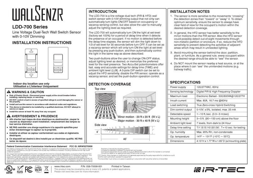
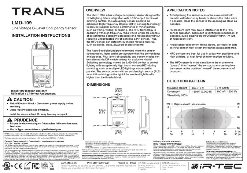
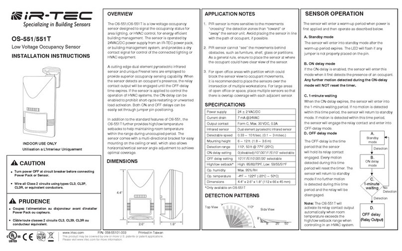
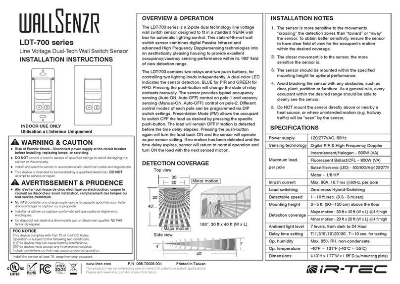
Lighting will be inhibited when the ambient light level is higher than the set threshold, regardless of occupancy or vacancy. When
the ambient light level is lower than the set threshold, the controlled light will be automatically turned on once the sensor detects the
presence of occupant, and turned off after the delay time elapsed.
NOTE:
This scheme can be used with
dimmable
or
non-dimmable
lighting, but not for HID lighting.
OSO
This is an
occupancy sensing control
scheme can be applied in areas that require 24-hour lighting. When space is vacant, the lights
will be maintained at Low Dim level. Whenever space is occupied, lighting output will be increased to High Dim level or continuously
regulated to maintain within the pre-set range by SmartDIM control.
NOTE:
Do
NOT
use this scheme to control
non-dimmable
lighting.
OSLA
This is an
occupancy sensing control
scheme can be applied in spaces that require automatic lighting when the ambient light level is
lower than the set threshold.
Lighting will be inhibited if the ambient light level is higher than the set threshold, regardless of occupancy or vacancy. When the
ambient light level is lower than the set threshold, the sensor will automatically control the light at Low Dim level. When sensor detects
the presence of an occupant, lighting output will be increased to the High Dim level or continuously regulated within the pre-set range
by SmartDIM control. After the delay time elapsed, lighting output will be reduced to Low Dim level or shut off if the ambient light is
higher than the set threshold.
NOTE:
Do
NOT
use this scheme to control
non-dimmable
lighting.
OSLATO
This is an
occupancy sensing control
scheme can be applied in spaces that require maintaining Low Dim lighting for a period of time
before shutting off.
Lighting will be inhibited if the ambient light level is higher than the set threshold, regardless of occupancy or vacancy. When the
ambient light level is lower than the set threshold, and any sensor detects the presence of occupant, lighting output will be increased to
High Dim level or continuously regulated to maintain overall lighting level within the pre-set range by SmartDIM control. After the delay
time elapsed, lighting output will be reduced to Low Dim level for a period of TIME OFF delay before shut off.
NOTE:
This scheme requires
dimmable
lighting to enable dimming control. If lighting is
non-dimmable
, there will be no dim control
and the delay time will be extended with the TIME OFF (TO) delay.
DSVM
This is a
daylight sensing control
scheme can be applied in spaces that require automatically dimming the lighting output to a low
level between a certain time before and after virtual midnight.
Lighting will be inhibited if the ambient light level is higher than the set threshold. When the ambient light level is lower than the set
threshold, the sensor will turn the light to High Dim level or continuously regulate the output to maintain overall lighting level within the
pre-set range by SmartDIM control. Lighting output will be reduced to Low Dim level from a certain time before virtual midnight to a
certain time after.
NOTE:
This scheme requires
dimmable
lighting to enable dimming control. If lighting is
non-dimmable
, all lights will remain on
whenever ambient light level is lower than the set threshold.
DSC
This is a
daylight sensing control
scheme can be applied in spaces that require automatic lighting whenever the ambient light is lower
than the set threshold.
The sensor will automatically turn on the light to High Dim level or continuously regulate the output to maintain overall lighting level
within the pre-set range by SmartDIM control when the ambient light level is lower than the set threshold, and automatically turn off the
light when the ambient light level is higher than the set threshold.
NOTE:
This scheme requires
dimmable
lighting to enable dimming control. If lighting is
non-dimmable
, all lights will remain on
whenever ambient light level is lower than the threshold.
VSC
This is a
vacancy sensing control
scheme can be applied in spaces that require users to manually turn on the light, and have the
sensor turn off the light automatically.
The occupant would have to press the OS-NET Button to turn on the lighting group assigned. The sensor will control the lights at High
Dim level or continuously regulate the output to maintain overall lighting level within the pre-set range by SmartDIM control. The sensor
will control the connected lighting as per OSLATO scheme.
NOTE:
This scheme requires
dimmable
lighting to enable dimming control. If lighting is
non-dimmable
, there will be no dim control
and the delay time will be extended with the TIME OFF (TO) delay.
OSB
This is an advanced
occupancy sensing control
scheme can be applied in open offices to provide background light level before the
area of entire lighting group is vacant.
Lighting will be inhibited if the ambient light level is higher than the set threshold, regardless of occupancy or vacancy. When the
ambient light level is lower than the set threshold and the first occupant is detected by a grouped sensor, the output of sensor
connected light will be increased to High Dim level or continuously regulated within the pre-set range by SmartDIM control during
occupancy, and the unoccupied areas of entire lighting group will brighten up to Low Dim level as background light. The entire lighting
group turns off after the last person leaves and delay time elapsed.
NOTE:
Do
NOT
use this scheme to control
non-dimmable
lighting.
OFF
This is a
manual control
scheme can be used when you need the light to be off for a certain period of time.
Once this scheme is set, all OS-NET controlled lighting will remain off until another scheme is selected.
Federal Communication Commission Interference Statement
This device complies with Part 15 of the FCC Rules. Operation is subject to the following
two conditions: (1) This device may not cause harmful interference, and (2) this device
must accept any interference received, including interference that may cause undesired
operation.
This equipment has been tested and found to comply with the limits for a Class B digital
device, pursuant to Part 15 of the FCC Rules. These limits are designed to provide
reasonable protection against harmful interference in a residential installation. This
equipment generates, uses and can radiate radio frequency energy and, if not installed
and used in accordance with the instructions, may cause harmful interference to radio
communications. However, there is no guarantee that interference will not occur in a
particular installation. If this equipment does cause harmful interference to radio or
television reception, which can be determined by turning the equipment off and on, the
user is encouraged to try to correct the interference by one of the following measures:
-Reorient or relocate the receiving antenna.
-Increase the separation between the equipment and receiver.
-Connect the equipment into an outlet on a circuit different from that to
which the receiver is connected.
-Consult the dealer or an experienced radio/TV technician for help.
FCC Caution: Any changes or modifications not expressly approved by the party
responsible for compliance could void the user's authority to operate this equipment.
This transmitter must not be co-located or operating in conjunction with any other
antenna or transmitter.
Radiation Exposure Statement:
This equipment complies with FCC radiation exposure limits set forth for an
uncontrolled environment. This equipment should be installed and operated with
minimum distance 20cm between the radiator & your body.
FCC ID: NRIRS420900
Industry Canada statement: IC: 22993-209RS4AC901
This device complies with ISED’s licence-exempt RSSs. Operation is subject to the
following two conditions: (1) This device may not cause harmful interference, and
(2) this device must accept any interference received, including interference that
may cause undesired operation.
Le présent appareil est conforme aux CNR d’ ISED applicables aux appareils radio
exempts de licence. L’exploitation est autorisée aux deux conditions suivantes : (1)
le dispositif ne doit pas produire de brouillage préjudiciable, et (2) ce dispositif doit
accepter tout brouillage reçu, y compris un brouillage susceptible de provoquer un
fonctionnement indésirable.
Radiation Exposure Statement:
This equipment complies with ISED radiation exposure limits set forth for an
uncontrolled environment. This equipment should be installed and operated with
greater than 20cm between the radiator & your body.
Déclaration d'exposition aux radiations:
Cet équipement est conforme aux limites d'exposition aux rayonnements ISED
établies pour un environnement non contrôlé. Cet équipement doit être installé et
utilisé à plus de 20 cm entre le radiateur et votre corps.
