Sensit PMD2 User manual

851 Transport Drive • Valparaiso, IN 46383 (USA)
Phone: 219.465.2700 • www.gasleaksensors.com
INSTRUCTION MANUAL
READ AND UNDERSTAND INSTRUCTIONS BEFORE USE.
For use with combustible gases and optionally available oxygen and toxic gases.
SENSIT®PMD2
PORTABLE METHANE DETECTOR


3
FOR YOUR SAFETY
⚠NOTICE: This safety symbol is used to indicate a potentially
hazardous situation which, if not avoided, may result
in minor or moderate injury.
⚠ WARNING: To reduce the risk of ignition of a flammable
atmosphere, batteries must only be changed and
charged in an area known to be nonflammable.
⚠ WARNING: Do not mix batteries of different age or type.
⚠ WARNING: Not for use in atmospheres of oxygen greater than
21%.
⚠ WARNING: Only zero the instrument in a gas free environment.
⚠ WARNING: To maintain intrinsic safety, service must be
performed by factory authorized technicians with
approved replacement parts only. No substitution of
components is permitted.
⚠ WARNING: All accessories are to be used in an area known
to be non-flammable.
⚠ WARNING: To prevent ignition of flammable or combustible
atmospheres, disconnect power before servicing.

4
CONTENTS
FOR YOUR SAFETY����������������������������������������������������� 3
QUICK START GUIDE�������������������������������������������������� 6
PRODUCT FEATURES: HARDWARE������������������������������� 7
RECHARGEABLE BATTERY AND CHARGING STATION.............................. 7
PUMP AND SAMPLING SYSTEM ............................................................. 7
LED BARS............................................................................................. 8
PRODUCT FEATURES: SOFTWARE�������������������������������� 9
WORK DISPLAY OPTIONS ..................................................................... 9
LEL DEFINITION.................................................................................... 10
ALARMS .............................................................................................. 10
OPERATION AND USE������������������������������������������������ 11
POWER-ON AND STARTUP SEQUENCE.................................................. 11
BUMP TESTING AND CALIBRATION ....................................................... 11
THE WORK DISPLAY.............................................................................. 12
FILTER INTEGRITY AND FLOW BLOCK CHECK ......................................... 12
READY FOR USE ................................................................................... 12
POWER OFF & BATTERY CHARGING...................................................... 13
QUICK MENU TEST MODES ���������������������������������������� 14
TICK .................................................................................................... 15
BAR HOLE TEST .................................................................................... 16
STANDBY MODE .................................................................................. 17
PEAK MODE ........................................................................................ 18
USER MENU �������������������������������������������������������������� 19
SET DATE ............................................................................................. 20
SET TIME.............................................................................................. 21
TIME ZONE.......................................................................................... 22
BUMP TEST........................................................................................... 23
CALIBRATION....................................................................................... 24
CAL LOG ............................................................................................. 25
SESSION LOG ...................................................................................... 26
BAR HOLE LOG .................................................................................... 27
CALIBRATION NEXT DUE....................................................................... 28
BAR HOLE PURGE THRESHOLD .............................................................. 29

5
NOTES ���������������������������������������������������������������������� 30
EQUIPMENT (WEEE) DIRECTIVE ����������������������������������� 31
WARRANTY �������������������������������������������������������������� 32

6
QUICK START GUIDE
1. Remove the instrument and rechargeable battery pack from the carrying case. If the battery
pack is not installed, install the battery into the instrument by sliding it in place, and install
the screws.
2. Press and hold the Abutton until the instrument powers on. The LED bars will illuminate
and the SENSIT logo will be shown on the display.
3. In clean air, allow the instrument to go through the startup sequence, warmup, and Autozero.
This typically takes 45 seconds or less but can take up to 5 minutes.
4. Anautomaticowblocktestmaybepromptedduringstartup.Ifso,placeyourngerover
the inlet at the end of the inlet and wait until the test passes. This should happen within 5
seconds.Ifowblockcannotbeachievedmakesurethelterisinstalledtightontheinlet
capandreplacetheO-ringonthelter,contactSENSIT Technologies for assistance.
Iftheautomaticowblocktestisnotpromptedduringstartup,performthistestafterthe
Autozero is complete and the work display is shown.
FLOW BLOCKED
will be displayed.
NOTE: If any FAIL messages occur during the Autozero, ensure that the instrument is in clear
air, and attempt the zero again by pressing and holding the Cbutton until
AUTOZERO
is shown on the display. Contact SENSIT Technologies if the instrument cannot pass the
Autozero.
4. The work display will be shown with the gas reading. Once this is shown with no fail
messages,andaowblockcheckhasbeensuccessful,youarereadytousetheinstrument.
5. Following federal, state, municipal, and/or company procedures, conduct the leak
investigation, survey, or other procedures as needed. See the Operation and Use and
Quick Menu Test Modes sections in the instruction manual for detailed information.
6. If the source of an odor or known leak needs to be pinpointed, use the
TICK
feature. To
enable, press and release the Bbutton to enter the
QUICK
MENU
. Press and release the
Bbutton again to enable
TICK
.
An audible ticking sound will be heard. Move the end of the probe or tubing towards the
area suspected of leakage. As you get closer to the source, the tick rate will increase. Press
and release the Bbutton or roll back the thumb wheel to decrease the tick. Press and
release the Abutton to deactivate.
7. To zero out very small levels of gas, press and hold the Cbutton until
AUTOZERO
is
shown on the display. This should only be done to set the instrument zero to your working
environment,(e.g.tozerooutasmalllevelofCOonastreetwithheavyvehicletrafc).The
instrument will not allow a zero if unsafe levels of gas are present and will show a fail message.
Note: If the PMD2 is set to show absolute readings instead of relative, performing an
Autozero will not zero the instrument to 0ppm.
8. When your investigation is complete, press and hold the Abutton until the instrument
displays
POWER OFF SHUTDOWN.

7
PRODUCT FEATURES: HARDWARE
RECHARGEABLE BATTERY AND CHARGING STATION
The SENSIT PMD2 comes standard with a rechargeable battery pack. This battery pack is
installed in the body of the instrument and secured with a door and two screws. The battery
pack can be charged while still installed in the instrument, or when removed, with the included
charger. The charger has status LEDs on it to indicate the charging status of the battery.
PUMP AND SAMPLING SYSTEM
All SENSIT PMD2 instruments are equipped with a powerful and efficient pump operates at
1.0 L/min,1.5 L/min, or 2.0 L/min, depending on what is specified at the time of order.
A 0.45 micron hydrophobic dirt and water filter installed in the inlet assembly protects the
internals of the instrument from foreign material. There is an additional internal filter that also helps
to protect the internals from larger damaging debris. If water or dirt does enter the instrument
causing the flow to be restricted, a flow blocked message will be displayed.
⚠ WARNING: Operating the SENSIT PMD2 with a damaged or altered filter can
cause damage to the instrument and void the warranty.

8
LED BARS
The LED bars on the SENSIT PMD2 display different colors and patterns to alert the operator
of various conditions. See the chart below for information on each�
COLOR INDICATION
Solid Green “Ready” indication. No current alarm condition or failure.
Blinking Green Low battery indication. The work display will also give an indication on screen to alert
the operator.
Blinking Red 1. Any alarm conditions.
2. Sensor failure/fault.
Solid Blue Busy, not in gas detection mode (e.g., viewing logs, SMARTLINK,
SMART-CAL 360 Communication)

9
PRODUCT FEATURES: SOFTWARE
WORK DISPLAY OPTIONS
COMBUSTIBLE GAS SCALE AND RESOLUTION
The combustible gas reading will be automatically displayed in one of three options on the
SENSIT PMD2: PPM, %LEL, or %VOL. By default, the reading starts in the PPM scale (from
0.0ppm) and will automatically switch to %LEL above 5000ppm (configurable) and then to %VOL
above100%LEL (equal to 5.0%VOL by default, see the section on LEL Definition).
If the PPM option is enabled, the PMD2 will instead start at 0.0PPM or an absolute value,
and automatically scale to either %LEL (if enabled) or %VOL at the specified upper limit. By
default, this is 2,000PPM. Other options are 5,000PPM, 10,000PPM, or 50,000PPM. If set to
50,000PPM, the PMD2 will not scale to %LEL even if it is enabled, because at the highest LEL
Definition, 50,000PPM is equal to 100%LEL.
In addition, the display resolution for the PPM and %LEL scales are customizable. The default
display resolutions and options for each scale, while on the work display, are listed below.
DEFAULT RESOLUTION
PPM 0.1PPM 0.1PPM, 1PPM or 10PPM
%LEL 0.1%LEL 0.1% - 2.0%LEL
[0.1% increments]
%VOL <5.0%VOL: 0.01%VOL
≥5.0%VOL:0.1%VOL Not adjustable

10
LEL DEFINITION
By default, the SENSIT PMD2 defines the lower explosive limit (LEL) as 5.0%VOL methane. This
is factory adjustable between 4.0% and 5.0% for methane in 0.1% increments, based on
company or industry requirements. This will affect how the instrument displays the %LEL scale. For
example, if the LEL definition is 4.0%VOL, 2.5%VOL methane will display as 62.5%LEL. See the
chart below for examples for natural gas�
ALARMS
The SENSIT PMD2 has audible and visual alarms to warn the operator when hazardous
conditions are being sensed. The alarm setpoints specific to the work display and are outlined
below. The LED bars on the PMD2 changes color based on alarm conditions. See the following
sections for information on each.
WORK DISPLAY ALARMS
WORK DISPLAY
ALARM SETPOINTS
DEFAULT
LEL 50.0%LEL
EX - PPM 10PPM
UEL SETPOINTS DEFAULT
NAT 17.0%VOL

11
OPERATION AND USE
⚠ CAUTION: Always start any SENSIT PMD2 in a gas free environment to ensure a
proper zero.
NOTE: Fully read and understand this section of the instruction manual before using your
SENSIT PMD2.
This section of the manual outlines the operation and use of the SENSIT PMD2 by general
categories. Due to the many custom options available, and many different applications the
instrument can be used in, there is not one comprehensive sequential set of instructions for using
the instrument. For a quick list of instructions to get up and running, see the Quick Start Guide at
the beginning of this manual, use this Operation and Use section for more detailed instructions,
and use the sections that cover the Quick Menu and User Menu for more specific instructions for
each test mode and menu.
POWER-ON AND STARTUP SEQUENCE
Before powering on the SENSIT PMD2, ensure that you are in a gas free environment, and
that you have a charged battery pack installed in the instrument, secured with the battery door.
Press and hold the Abutton until the SENSIT logo appears on the display and the LED bars
illuminates. The instrument will not be ready to use until it reaches the work display, and both a
successful autozero and flow block check have been performed. The startup process will take less
than 45 seconds typically but can take up to a maximum of 5 minutes depending on the output/
stability of the sensor.
BUMP TESTING AND CALIBRATION
To verify the accuracy of any SENSIT PMD2, it must be exposed to a known concentration
of test gas that will test the sensor response. This is known as “bump testing”. This can be done
either by exposing the instrument to gas from the working display or using the bump test feature
which tests the sensor and gives a pass or fail message. For more information, see the Bump Test
section in this manual.
A sensor that does not meet the specifications listed in this manual may require calibration or
repair. A bump test does not calibrate the unit and does not update the calibration due date. Full
calibration is required for that.
A calibration past due message will be displayed during startup if calibration has not been
performed per your company specified interval. Any time it is suspected that the SENSIT PMD2
is not working properly, check calibration.

12
THE WORK DISPLAY
After the startup process, the work display will be shown. This is the main working screen of the
instrument, and what will be used most of the time when detecting gas. The live gas reading is
shown on screen.
FILTER INTEGRITY AND FLOW BLOCK CHECK
Prior to use, a flow block check needs to be performed to test the integrity of the filter and
internal tubing. Block the inlet of the instrument or attached probe. Within a few seconds,
FLOW
BLOCKED
should be shown on the display. This ensures all seals are intact and there are no air
leaks in the probe or instrument. Press and release the Cbutton to restart the pump and return to
the previous screen. If flow block is not detected, check the integrity of the filter and connections
on the probe and instrument. If flow block cannot be achieved, contact the factory for assistance.
An airtight system is crucial for accurate readings.
READY FOR USE
After the startup process and Autozero are complete, and a successful flow block check has
been done, the instrument is ready for use. The “work display”, which is shown, will show live
gas readings. The operator does not need to leave this screen for most general-purpose use.
However, there are a few specialized test modes for specific applications, such as bar hole testing
and tick. See the Quick Menu section for more information on these.
To use the SENSIT PMD2 for gas detection, always follow federal, state, municipal, and/or
company procedures, then follow these generalized steps below for using the SENSIT PMD2.
1. It may be necessary to manually zero the instrument based on company practices and
environmental conditions. To do so, press & hold the Cbutton until
AUTOZERO
appears at
the top of the screen. Always zero the instrument in a clean air environment. If the instrument
is setup to display absolute readings, an Autozero will not set the instrument to 0ppm.
2. Alwaysperformaowblockcheckwhenusinganyprobeorattachment.
3. When sampling the sensor will cause the display to update when methane is encountered.
A combination of LED patterns and messages on the work display will occur when the
preset concentrations are reached. If any alarm condition exists, based on the preset alarm
points,theredLEDwillash,andthealarmwillsoundunlessitismuted.Additionally,the
readingwillashonscreen.ThestandardalarmsandLEDpatternscanbefoundinthe
features section.
4. To mute the alarm, quickly press and release the Abutton. To unmute the alarm press and
releasethesamebuttonagain.Duringanalarm,thereadingwillashonthedisplay,and
theredLEDwillashindicatingapotentiallyunsafecondition.Whenmethanereadings
exceed the alarm range UEL, the audible alarm will turn off. If the alarm condition no longer
exists or was muted, the alarm sound will activate if a new alarm condition is encountered.
5. To assist in locating small leaks, utilize the
TICK
feature. See the Quick Menu section for
more information.
6. Following Federal, State, Municipal and/or Company procedures move to the areas where
gas readings are suspected or must be tested. Use the proper accessories to draw samples
into the instrument. During sampling, the respective readings may change. Audible and
visual alarms will activate when the preset limits are reached.

13
POWER OFF & BATTERY CHARGING
POWER OFF
To power off the SENSIT PMD2, ensure you are in a gas free environment, and then press and
hold the Abutton until the power off screen is shown. The instrument will purge for 10 seconds
(by default) and then power off. During this purge, you can press and release the Abutton
again to stop the power off process.
BATTERY CHARGING
The SENSIT PMD2 battery pack can be charged installed in the instrument or standalone. In
both cases the charger is plugged directly into the battery pack. Status LEDs are located on the
charger to show when the battery pack is charging, charged, and if there are any issues such as
the pack being outside of the allowable temperature range for charging.

14
QUICK MENU TEST MODES
Depending on what type work the SENSIT PMD2 is being used for, there are a variety of test
modes available that are designed to be used for specific tasks. For example, using
Bar hole
mode for below-grade leak investigation.
To access these test modes, enter the Quick Menu from the working display by pressing and
releasing the Bbutton.
QUICK MENU
will appear near the top of the display. You can scroll
through this menu by pressing and release the Cbutton, and selecting the mode currently shown
on screen by pressing and releasing the Bbutton. See the following sections for information
about these test modes.

15
TICK
STANDARD FEATURE
PURPOSE: Assist in pinpointing small combustible gas leaks
TICK
mode is a standard feature in the SENSIT PMD2. It gives the operator a ticking,
audible tone that gets faster as the gas concentration increases. This assists in pinpointing small
combustible gas leaks by allowing the operator to rely on the tone and not have to watch the
display of the instrument. It detects very small changes in gas concentration, which lets the
operator very accurately and repeatably pinpoint the source of the leak.
The tick can be very gradually adjusted with the thumbwheel on the top of the instrument or can
be instantly reset to a “baseline” tick rate by using the Bbutton. This gives the operator a lot of
control, and as the leak is searched for, small changes can be made to narrow down the source.
TO USE TICK:
1. From the working display, press and release the Bbutton to enter the
QUICK MENU
. The
rstoptioninthemenuistick.
2. Press and release the Bbutton to enable it. Upon activation, an audible tick can be heard,
and a bar graph is displayed. The bar graph is a visual representation of how fast the tick
rate (empty bar = no tick, full bar = max tick). To pinpoint a leak, move the probe toward the
area suspected of leakage. As you move closer to a leak source, the tick rate will increase.
When the tick becomes a steady tone, either rotate the thumbwheel to decrease the tick rate
or press and release the Bbutton to reset the tick rate to the baseline level. Then, a higher
concentration of gas can be searched for using the same procedure. When this process no
longerndsahigherconcentration,thesourceoftheleakhasbeenpinpointed.
3. If the tick slows down or goes away, you have moved away from the leak or there is no
more gas present.

16
BAR HOLE TEST
STANDARD FEATURE
PURPOSE: Below grade leak investigation
LOG SIZE: 2,048 Records
BAR HOLE MODE
is a default feature in the SENSIT PMD2. It is intended for use when
conducting a below grade leak investigation, generally in a hole bored in the ground with a
plunger bar or drill. It gives the operator a separate screen from the working display that shows
the combustible gas reading in the %VOL scale (both real time and peak reading).
Bar hole mode is a timed test, which helps to ensure consistent results are achieved if multiple
tests are done, whether to grade a leak or map leak migration. Each
BAR HOLE
test is logged in
its own log, with results, date and time, and GPS coordinates (if installed), that can be retrieved
wirelessly from the SENSIT PMD2 with Smart-Link 360 Software.
TO CONDUCT A BAR HOLE:
1. If you are sampling below grade in a hole, a bar hole probe is required for use while in this
mode.Attachthebarholeprobetothettingtotheinletoftheinstrumentandperforma
owblockcheckbyblockingtheinlet(s)oftheprobe.Within10seconds,
FLOW BLOCKED
should be shown on the display. This ensures all seals are intact and there are no air leaks
in the probe or instrument. Press and release the Cbutton to restart the pump and return
tothepreviousscreen.Ifowblockisnotdetected,checkthe integrityofthelterand
connectionsontheprobeandinstrument.Ifowblockcannotbeachieved,contactthe
factory for assistance. An airtight system is crucial for accurate readings.
2. From the working display, press and release the Bbutton to enter the
QUICK MENU
.
3. Press and release the Cbutton until
Bar hole TEST
is shown.
4. Press and release the Bbutton to enter
Bar hole TEST
mode. A message will be displayed
instructing you to attach hardware.
5. To begin a bar hole test, insert the probe into the location for the survey and then press and
release the Bbutton.A≤15secondcountdownforthetestwillstart(thetimemaydiffer
dependingonthepumpowrate).Thecurrentpercentofgasbyvolumedetectedwillbe
displayed on the left side of the display. The peak percent of gas by volume detected will
be displayed on the right side of the display. When the test ends, the pump will shut off and
any sustained and peak readings will be shown and recorded.
6. If you have another test to take, remove the probe from the test location and press and
release the Cbutton to purge the gas out of the instrument. The purge process will start
and continue until the desired setpoint is reached. This is set to 0.0%VOL by default and
adjustable in the User Menu. When the purge stops, insert the probe into the next location
and press and release the Bbutton to start another test.
7. To exit bar hole mode, press and release the Abutton once to return to the quick menu, or
twice to return to the work display.

17
STANDBY MODE
OPTIONAL FEATURE
PURPOSE: Puts the instrument in a low-power mode, for when you will need to use it again soon
and do not want to fully power it off and back on again.
The SENSIT PMD2 has an optional “standby” mode that allows the operator to put the
instrument in a low power state. This can be used if you don’t need to use the instrument for a
short amount of time and want to reduce battery consumption and time over fully powering the
instrument off and back on again.
TO ENABLE STANDBY MODE:
1. From the work display, press and release the Bbutton.
QUICK MENU
will appear near
the top of the display.
2. Press and release the Cbutton until
STANDBY
is shown.
3. Press and release the Bbutton to activate
STANDBY MODE.
The gas readings will be
removed and “STANDBY” will be shown on screen.
4. To resume normal operation and exit
STANDBY MODE
, press and release the Abutton. A
brief warmup will be shown to ensure sensor is stable/operational.

18
PEAK MODE
OPTIONAL FEATURE
PURPOSE: Maintaining peak readings on the display for situations where the screen cannot be
observed.
Work display peak readings in the SENSIT PMD2 is an optional feature that is used to
maintain peak readings on the display (in addition to the real-time readings). The most common
use case for this is when the instrument is being used in a situation where the display cannot be
immediately observed. The peak reading remains on the screen until cleared so that no readings
are missed.
TO ENABLE WORK DISPLAY PEAK READINGS:
1. From the working display, press and release the Bbutton.
QUICK MENU
will appear near
the top of the display.
2. Press and release the Cbutton until
PEAK MODE
is shown.
3. Press and release the Bbutton to enter
PEAK MODE
. The working display will be shown
with an additional peak reading in brackets below the real-time reading.
4. Conduct the investigation or survey following federal, state, municipal, and/or company
procedures. The highest measured value of combustible gas will be shown in addition to
themeasuredvalue.PPM,LEL,orVOLwillbeshowndependingoninstrumentconguration
and gas concentration measured.
5. To reset the peak readings, press and hold the Cbutton until
AUTOZERO
is displayed
(NOTE: this should be done in a gas free environment).
6. To exit the
PEAK MODE
, press and hold the Abutton for 2-3 seconds. The peak readings
will be removed, and the standard working display will be shown.

19
USER MENU
The SENSIT PMD2 has a user-accessible menu that is used for user-level tasks such as
performing a manual calibration, viewing logs, etc. A brief description of each menu option is
listed below, followed by more details for each in the following section(s). Any options that are
not available by default are listed as such (for example, a log for a non-default test mode).
Other non-user adjustable settings are in the password protected Expert Menu.
To access the USER MENU from the working display, press and hold the Bbutton until
USER
MENU
is shown near the top of the display. While in this menu, pressing and releasing:
• the Abutton will exit to the working display
• the Bbutton will select the currently shown option
• the Cbutton will scroll through each menu option
SET TIME Allows the user to adjust the instrument time in 24-hour format (hours and
minutes). When installed and configured, this is set automatically by GPS.
SET DATE Allows the user to adjust the instrument date (day, month, and year). When
installed and configured, this is set automatically by GPS.
TIME ZONE Allows the user to set the instrument time zone (hours and minutes). This is
an offset from UTC +0.
GPS OPTIONAL FEATURE
When installed and configured, this shows the status of the GPS signal
received by the instrument and the latitude and longitude coordinates.
BUMP TEST Perform automatic test for sensor response to calibration gas within 60
seconds or less. A response of 80% or greater of the calibration gas value
indicates a successful test.
CALIBRATION Contains options for
AUTOCAL
and manual calibration of of all calibration
points.
CAL LOG Displays historical calibration information.
SESSION LOG Displays manually saved gas readings.
BAR HOLE LOG OPTIONAL FEATURE
Displays automatically saved Bar hole records.
DATALOG OPTIONAL FEATURE
Displays automatically saved records from when the instrument is in use.
SMART CAL Communication mode used in conjunction with the SMART-CAL 360
calibration station.
NEXT DUE Displays the next calibration due date for all calibration points.
BAR HOLE PURGE Adjustment for the level of gas needed (in %VOL) for a Bar Hole purge to be
THRESHOLD complete. Default is 0.0%VOL.

20
SET DATE
STANDARD FEATURE
NOTE: If the CAL REQUIRED option is enabled, the SET DATE feature will not be available.
The
SET DATE
option allows the user to adjust the clock date saved in the SENSIT PMD2’s
internal memory. There are two ways in which the clock date can be automatically updated so
that this adjustment is never needed:
• SENSIT PMD2 instruments with GPS installed have the option to have the clock date be
automatically updated via GPS signal (date is received along with location information).
The
GPS CLOCK MODE
setting in the Expert Menu controls this.
• When a SENSIT PMD2 communicates with a SMART-CAL 360 calibration
station (e.g. for calibration or bump testing), the internal clock is automatically updated
and synchronized with the station clock. This is not optional and happens with every
communication, to avoid issues with instruments in the same fleet having mismatched
clocks.
TO VIEW OR ADJUST DATE:
1. To access the
SET DATE
menu from the working display, press and hold the Bbutton until
USER MENU
is shown near the top of the display. Press and release the Cbutton until
SET DATE
is shown. The currently saved instrument date will be displayed while viewing this
menu option. If an adjustment needs to be made, follow the instruction below.
2. Press and release the Bbutton to select the
SET DATE
menu. The
DAY
option will be shown.
3. Pressing and releasing the Cbutton will scroll through
DAY, MONTH
, and
YEAR
. To make
an adjustment to one of these, press and release the Bbutton.Thesettingwillbeashing.
4. Use the Band Cbuttons to adjust the number down or up.
5. When correct, press and release the Abutton to return to the
SET DATE
menu. If another
adjustment is needed, press and release the Cbutton to scroll to the appropriate option.
6. When the date is correct, press and release the Abutton to return to the User Menu. Press
and release the Abutton again to return to the work display.
Table of contents
Other Sensit Security Sensor manuals

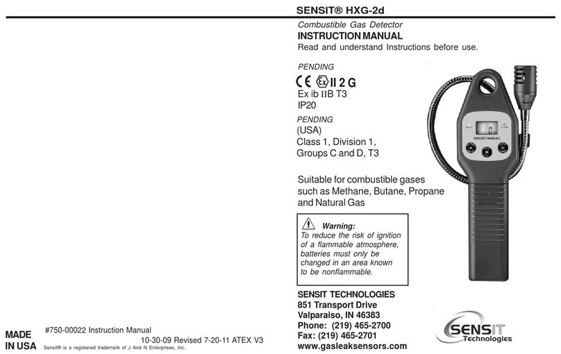
Sensit
Sensit HXG-2d User manual

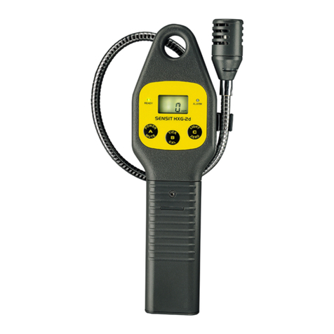
Sensit
Sensit HXG-2d User manual

Sensit
Sensit HXG-3P User manual

Sensit
Sensit CO Programming manual

Sensit
Sensit HXG-2d User manual

Sensit
Sensit HXG-3 User manual

Sensit
Sensit TKX User manual

Sensit
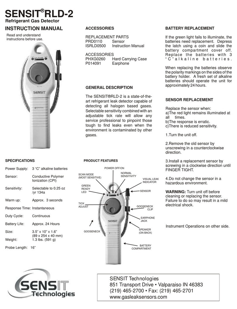
Sensit RLD-2 User manual

Sensit
Sensit VMD Operating instructions

Sensit
Sensit TKX User manual
Popular Security Sensor manuals by other brands

Electronics Line
Electronics Line EL-2800 installation instructions

Profort
Profort vibraSpot manual

Sensorio
Sensorio LZR -U901 user guide

DANLERS
DANLERS EasyZAPP EZ CEFL DALI Installation notes

Vega
Vega VEGAFLEX 81 operating instructions

Teletek electronics
Teletek electronics SensoMAG F10B Installation instruction