Sensor Therm METIS M3F1 User manual

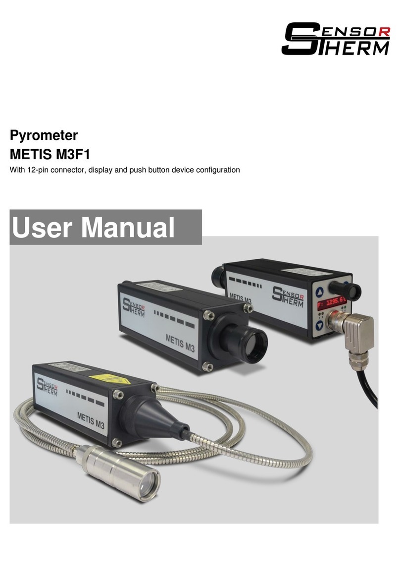
Pyrometer
METIS M3F1
With 12-pin connector, through-lens view finder and LEDs
User Manual

METIS M3F1
Content
2
Content
1General...............................................................................................................................................4
1.1 Information to this Manual.........................................................................................................4
1.2 CE Conformity and Standards..................................................................................................4
1.1 Limitation of Liability..................................................................................................................4
1.2 Terms of Warranty ....................................................................................................................4
1.3 Copyright...................................................................................................................................4
1.3 Explanation of Symbols ............................................................................................................5
1.4 Customer Service / Spare Parts ...............................................................................................5
1.5 Disposal ....................................................................................................................................5
2Safety..................................................................................................................................................6
2.1 General .....................................................................................................................................6
2.2 Electrical Connection ................................................................................................................6
1.6 Through-lens Sighting / View Finder.........................................................................................6
1.7 Responsibility of the Operators.................................................................................................6
3Overview ............................................................................................................................................6
3.1 Intended Use.............................................................................................................................6
3.2 Scope of Delivery......................................................................................................................6
3.3 Model Design............................................................................................................................6
4Electrical Connection........................................................................................................................7
4.1 Cable Colors and Pin Assignment (14 Wire Connection Cables).............................................7
4.1.1 Power Supply.......................................................................................................................8
4.1.1.1 Factory Settings..............................................................................................................8
4.1.2 Analog Output 1 and 2.........................................................................................................9
4.1.3 Configurable Inputs / Outputs..............................................................................................9
4.1.4 Serial Interface RS232 / RS485 (switchable) ....................................................................10
1.7.1.1 Interface Converter (Accessory)...................................................................................11
4.1.5 Shielding ............................................................................................................................11
5Mechanical Installation...................................................................................................................11
5.1 Mounting .................................................................................................................................11
5.2 Ambient Temperature.............................................................................................................12
5.3 Measuring Technology............................................................................................................12
5.4 Alignment with the Through-lens Sighting / View Finder........................................................12
5.5 Setting the Measuring / Focus Distance.................................................................................13
5.5.1 Manually Focusable Optics................................................................................................13
5.6 Spot Size Table.......................................................................................................................13
5.6.1 Calculation of the Spot Size Diameter outside the Focused Distance ..............................13
6Configuring the Pyrometer / Pyrometer Parameters...................................................................14
6.1 Soot Factor..............................................................................................................................14
6.2 Emissivity Slope (only when using the pyrometer as a usual ratio pyrometer)......................14
6.3 Emissivity ε (only when using as a usual single-channel pyrometer).....................................14
6.4 Transmittance .........................................................................................................................15
6.5 Spot Size Fill Factor................................................................................................................15
6.6 Switch-off Level.......................................................................................................................16
6.6.1 Switch-off Verification ........................................................................................................16
6.7 Dirty Window Alarm ................................................................................................................16
6.8 Response Time t90 ..................................................................................................................16
6.8.1 Dynamic Adaptation at Low Signal Levels ........................................................................16

METIS M3F1
Content
3
6.9 Maximum Value Storage (Peak Picker) / Clear Time tCL........................................................16
6.10 Temperature Sub Range ........................................................................................................17
6.11 Customize Analog Output.......................................................................................................17
6.12 Temperature Unit....................................................................................................................17
6.13 Analog Output.........................................................................................................................17
6.14 Upscale-Burnout .....................................................................................................................18
6.15 Interface Type.........................................................................................................................18
6.16 Baud Rate...............................................................................................................................18
6.17 Address...................................................................................................................................18
6.17.1 Interface Delay / Answer Delay .........................................................................................18
7SensorTools Software ....................................................................................................................19
7.1 Installation...............................................................................................................................19
1.8 Program Start..........................................................................................................................19
7.1.1 Connecting the Pyrometer.................................................................................................19
7.2 Software Window....................................................................................................................20
7.2.1 Main Window Graphs....................................................................................................20
7.2.2 Control Window .................................................................................................................22
7.2.3 Device Settings and Configuration ....................................................................................23
7.2.3.1 Configurable Inputs / Outputs.......................................................................................24
7.2.3.2 Data Collection (Buffer Mode)......................................................................................27
7.2.3.3 Single-Point Adjustment...............................................................................................28
7.2.4 Setups................................................................................................................................30
7.3 Data Playback.........................................................................................................................31
7.4 Communication / Options .......................................................................................................32
7.5 Spot Size Calculator ...............................................................................................................32
8SensorFlash Software (Update Firmware)....................................................................................33
9Technical Data.................................................................................................................................34
9.1 Storage ...................................................................................................................................35
9.2 Dimensions .............................................................................................................................35
9.3 Composition of the Type Number...........................................................................................35
9.4 Accessories.............................................................................................................................36
10 Maintenance.....................................................................................................................................37
10.1 Cleaning..................................................................................................................................37
10.2 Pyrometer Calibration.............................................................................................................37
10.3 Trouble Shooting.....................................................................................................................37
11 Communication via Serial Interface / Interface Commands .......................................................38
Index.........................................................................................................................................................42

METIS M3F1
General
4
1 General
1.1 Information to this Manual
This manual enables the safe and efficient use with the device. The manual is part of the instrument and
has to be kept in a location where users of the controller always have access to.
Read this manual carefully before operating. For secure working all security notes and operation proce-
dures in this manual has to be followed.
Additionally the local accident prevention regulations and common safety regulations of the instruments’
operational area are valid.
The descriptions may differ from the current delivery status, since the pyrometer is continuously devel-
oped. Illustrations in this manual are for basic understanding and can differ from the actual construction.
1.2 CE Conformity and Standards
The product conforms to the following standards:
CE conformity: DIN EN 61326-1 (electromagnetic compatibility)
RoHS: 2011/65/EU
1.1 Limitation of Liability
All information and notes in this manual are made under consideration of valid standards and rules,
state of technology and our expert knowledge for many years.
The producer assumes no liability for damages due to:
Non-observance of this manual
Usage out of intended use
Assignment of unskilled personnel
Unauthorized modifications
Technical modifications
Usage of spare parts not approved
The responsibilities of the delivery contract are valid as well as our general terms and conditions and
terms of delivery and the valid statutory rule at date of the conclusion of contract.
1.2 Terms of Warranty
A warranty period is 24 months from date of shipment form the Sensortherm facility. The seller will re-
pair or replace the device at its own discretion. Further claims of the buyer against the seller or its
agents are excluded, especially claims for damages that are not incurred in the delivery itself. This shall
not apply in cases of intent, gross negligence, or the absence of assured properties. Damage or misuse
of the product will be determined and void the warranty coverage. Repairs paid by the customer will in-
clude a 180 days warranty from date of shipment. Transportation costs are to be paid by the customer.
Any claims for damage caused by misuse, neglect or tampering with the sensor are excluded.
Sensortherm does not guarantee that the software is free of errors or programming errors.
1.3 Copyright
This manual is protected by copyrights and are intended solely for internal purposes.
It is not permitted to transfer these instructions to third parties, duplication in any kind and form - includ-
ing excerpts - as well as recovery and / or notification of contents without written permission of the man-
ufacturer, except are internal purposes.
Contraventions are liable for damages. All other rights reserved.

METIS M3F1
General
5
1.3 Explanation of Symbols
The following symbols are used in this manual for restrictions, preventive measures and security notes.
Please pay attention to these symbols for safety reasons.
WARNING!
This combination of symbol and signal word indicates a potentially dangerous situation that
can lead to death or serious injury if not avoided.
CAUTION!
This combination of symbol and signal word indicates a potentially dangerous situation that
can result in minor or moderate injury if not avoided.
NOTE:
This combination of symbol and signal word indicates a potentially hazardous situation that
can lead to property and environmental damage if not avoided.
INFO:
This symbol indicates useful tips, recommendations and information for efficient and trouble
free operation.
The identification label on top of the device contains the following infor-
mation: manufacturer, reference number, temperature range, serial num-
ber, serial interface output (=digital output), analog output, power supply,
country of manufacture and CE sign.
1.4 Customer Service / Spare Parts
For technical information contact our customer service.
It is recommended to purchase spare parts and accessories direct from Sensortherm (manufacturer).
In addition, our employees are always interested in new information and experiences arising from the
application and can be valuable for improvement of our products.
1.5 Disposal
Dispose of the product properly when it is no longer usable: pyrometers include electrical and electronic
waste and have to be recycled or disposed environmentally friendly or to send to the manufacturer for
disposal.
M3
F1 07501800058130423-A
Temp. Range: 750 - 1800 °C
1382 - 3272 °F
Serial #: 1234
Digital Output: RS 485
Analog Output: 2x 0/4 - 20mA
Made in Germany Power: 18 - 30V DC
Sensortherm GmbH

METIS M3F1
Safety
6
2 Safety
2.1 General
Any person who is tasked to carry out work with the device must have read and understood the operat-
ing instructions before beginning. Operation and maintenance of the system may only be performed by
trained personnel.
2.2 Electrical Connection
When connecting or when working on the mains voltage, the general safety guidelines are observed,
e.g. when connecting power transformers. Supply voltage can be lethal when touching. Improper instal-
lation can cause serious injury or physical damage. Only qualified personnel are allowed to work with
mains voltage.
1.6 Through-lens Sighting / View Finder
Devices with through lens sighting and temperature range above 1400°C are equipped with an adjusta-
ble eye protection filter in the eyepiece to reduce glare at high measurement temperatures. The unpro-
tected look at temperatures >1400°C can damage the eyes function permanently.
Safety precaution: before looking toward the high temperatures, always first adjust the eyepiece with
help of a replacement light source by turning onto the darkest area. A safe method is the adjustment by
looking at a lamp.
1.7 Responsibility of the Operators
If the device is used in the commercial sector the operator is subject to the legal responsibilities for
workplace safety.
In addition to the safety instructions in this manual follow the regulations of safety, accident prevention
and environmental protection.
3 Overview
3.1 Intended Use
The M3F1 is a special pyrometer of the Metis M3 series for non-contact infrared temperature measure-
ment of flames containing soot in coal-fired power plants, waste incineration plants and other combus-
tion furnaces.
3.2 Scope of Delivery
Pyrometer, software SensorTools, works certificate, user manual
(Note: Connection cables are not included in scope of delivery and have to be ordered separately).
3.3 Model Design
Type label
Optics
Through-lens sighting
/ view finder
Mounting thread (M5) for
front mounting the pyrome-
ter or accessory
Mounting rail (bot-
tom of the device)
Electrical connection
LEDs for monitoring the
operational readiness
(4) or active switching
outputs (1-3)

METIS M3F1
Electrical Connection
7
4 Electrical Connection
4.1 Cable Colors and Pin Assignment (14 Wire Connection Cables)
The electrical connection of the pyrometer (supply voltage and measuring signal) will be done via the
connector on the rear panel. For this purpose, pre-assembled connection cables are available as ac-
cessories (see 9.4 Accessories). To prevent accidental short circuits, cable wires not in use should be
secured to the supplied screw terminals.
Cable colors
Sensortherm
pyrometers
No.
Function
Pin
White
1
+ 24 V DC power supply (18–30 V DC)
K
E
DMH
J
L
C
BAK
FG
Connector pins
of the 12 pin
pyrometer connector
(view from outside)
Brown
2
0 V DC power supply (ground)
A
Green
3
+ Analog output 1 (0 / 4–20 mA)
L
Yellow
4
- Analog output 1 (0 / 4–20 mA)
B
White-green
14
+ Analog output 2 (0 / 4–20 mA)
D
Brown-green
15
- Analog output 2 (0 / 4–20 mA)
B
Grey
5
Digital input / output 1 1)
H
Pink
6
Digital input / output 2 1)
J
Blue
13
Digital input / output 3 / Analog in 1)
E
Black
9
RS232: RxD
RS485: B (+)
F
Grey-pink
11
Violet
10
RS232: TxD
RS485: A (-)
C
Red-blue
12
Red
8
DGND (ground for interface)
G
Orange
7
Shield (connect only for cable extension,
do not connect in the control cabinet)
M and plug housing
1) Reference potential 0 V, brown
NOTE: In general we recommend the use of the new 14 wire connection cables.
Be careful when using an old 12-wire connector cables (before 2015):
Connection cable for the previous models Metis and Sirius cannot be connected without re-
strictions on a M3 pyrometer!
Old connection cables are bridged in the cable connector to pins E-C and D-F. Connecting such a ca-
ble to a M3 pyrometer, serial interface and analog output 2 and digital input / output 3 are connected
and the galvanic isolation between the outputs is bypassing. Thereby the pyrometer is not destroyed,
but the functions are no longer available. Using such a cable only analog output 1 is available as output.
Cable colors
old Sensor-
therm cable
Function
Pins
White
Power supply +24 V DC
K
E
DMH
J
L
C
BAK
FG
Connector pins
cable socket (solder side)
Brown
Power supply 0 V DC (ground)
A
Green
+ Analog output (0/4–20 mA)
L
Yellow
- Analog output (0/4–20 mA)
B
Grey
Targeting light, external switch (bridge to K)
H
Pink
Maximum value storage, external clearing (bridge to K)
J
Orange
Screen
M
Red
DGND (Ground for interface)
G
Black
RxD (RS232) or B1 (RS485)
F
Violet
TxD (RS232) or A1 (RS485)
C
Grey / pink
RxD (RS232) or B2 (RS485) (bridge to F)
D
Red / blue
TxD (RS232) or A2 (RS485) (bridge to C)
E

METIS M3F1
Electrical Connection
8
M3
0 V
White
Brown
+24 V
LED4:
Operating
status LED
4.1.1 Power Supply
With connection of the supply voltage (standard 24 V DC, possible range 18–
30 V) the unit is ready for operation with the following factory settings (changing
the settings is possible via Software SensorTools (see 7). By connecting the
power supply, the current firmware version is displayed for a few seconds.
Interrupt the power supply to turn off the pyrometer, e.g. by disconnecting the
connector.
Power status LED: Indicates the operating status of the pyrometer:
orange in the self-test phase (ca. 2 s; )
Green when the pyrometer is ready to operate
Red when an error occurred (see 10.3 Troubleshooting).
4.1.1.1 Factory Settings
Parameters Factory Settings
Temperature sub range ........................................ Corresponds to basic range
Response time t90 ................................................. Min / 0,0 (corresponds to <1 ms)
Soot factor............................................................. 1.00
Emissivity slope .................................................... 1.000
Switch-off limit....................................................... 10%, hysteresis: 2%
Switch-off verification............................................ 10 ms
Emissivity ε (channel 1 and 2) .............................. 1.00 (corresponds to 100%)
Transmittance ....................................................... 100%
Spot size fill factor................................................. 100%
Serial interface RS232 / 485................................. RS485
Data transmission speed (baud rate).................... 115.2 kBd
Buffer mode........................................................... off (at “on”: buffer interval: 10 ms, single reading)
Device address ..................................................... 00
Interface delay ...................................................... 00 (for RS232 and RS485)
Maximum value storage........................................ off
Analog output 1..................................................... 4–20 mA, output temperature: measured temperature
Analog output 2..................................................... 4–20 mA, output temperature: no temperature output
Digital input / output 1 ........................................... set to input: no function
Digital input / output 2 ........................................... set to input: maximum value storage external clearing
Digital input / output 3 / Analog in......................... set to input: no function
Input debounce time........................................ 100 ms
Output activation time ..................................... 0 ms
Output hold time.............................................. 10 ms
Limit switch output........................................... center of temp. range °C / °F; hysteresis: 10°C / 20°F
Device over temperature................................. 50°C / 120°F; hysteresis: 2°C / 5°F

METIS M3F1
Electrical Connection
9
Max. 50 mA
0 V
M3
Output
+24 V
100 kΩ
White
Grey
Pink
Blue
Brown
0 V
M3 / H3
0...20 mA
4...20 mA
A
0...20 mA
4...20 mA
A
+IOUT1
-IOUT1
+IOUT2
-IOUT2
Green (+)
Yellow (-)
Brown-green (-)
White-green (+)
Note: The outputs are galvanically
isolated from the supply voltage.
4.1.2 Analog Output 1 and 2
The analog outputs are adjustable (e.g. for a temperature dis-
play device) to:
0–20 mA or 4–20 mA
Furthermore, the following adjustments can be done:
Analog Output 1 always provides the measured tempera-
ture (always the temperature selected and displayed on the
device display and the control window in SensorTools; see
also 7.2.2 Control window).
(Note: With older firmware versions, the same settings are
possible as at analog output 2. A firmware update to the lat-
est version eliminates this possibility and prevents, that the output of analog output 1 is accidentally
different to the displayed temperature signal. Firmware update see section 8).
Analog Output 2 can be assigned to provide different signals:
- Flame temperature
- 2-color temperature
- 1 channel temperature (optional channel 1 or 2)
- Device temperature
- Control output (= manipulated variable) when equipped with PID controller
4.1.3 Configurable Inputs / Outputs
3 ports are each available as:
Digital output: output of a switching signal (invertible, see under
7.2.3 Various settings Logic NO / NC) at:
- Device ready to operate (device ready and error-free after self-
test)
- Material detection (limit switch turns on when exceeding the
beginning of temperature range)
- Limit switch when a certain temperature threshold is exceeded
or falling below
- Exceeding the maximum allowed device temperature
- Signal strength too low (as dirty window alarm function: enables to detect the degree of contamina-
tion of the pyrometer‘s optics, viewing window or identify interferences (dust...) in the IR sensor’s
sight path and trigger an alarm if necessary).
Digital input: A voltage pulse of 24 V, pulse
length adjustable via software (minimum 3 ms,
factory settings 100 ms) 7.2.3 Configurable
Inputs / Outputs debounce time enables:
- Clear of maximum value storage (see 6.9)
- Load pyrometer configuration (see under 7.2.3
Configurable Inputs / Outputs “parame-
ter selector” or 7.2.4 Setups).
Analog input (only M3 and only on input / output 3, adjustable
via Software, see Analog Input): About a 0–20 mA current
source, some parameters can be adjusted externally between
their smallest and largest setting value:
- Soot factor (0 mA = 0.5; 20 mA = 2.5)
- Emissivity slope (0 mA = 0.8; 20 mA = 1.2)
- Emissivity for every channel (0 mA = 0.05; 20 mA = 1.2)
M3
>10 kOhm
0 V
+24 V
Input 1-3
Push
button
0 V
+24 V
White
Grey
Pink
Blue
Brown
Setpoint input
via external
0...20 mA
0 V
Current source
M3
Blue
Brown
≤300 Ω

METIS M3F1
Electrical Connection
10
4.1.4 Serial Interface RS232 / RS485 (switchable)
The serial interface is used for digital communication of the pyrometer with another computer, for exam-
ple a PC for data transmission to the software SensorTools. Via interface always all temperatures are
transferred (2-color and one channel temperatures) as well as device information and parameters.
The maximum transmission speed (in Baud) is limited by the cable length, it is halved with each dou-
bling of the transmission path.
RS232: about 7 m cable length with 19.2 kBd. Adjustable are values from 4.8 to 115.2 kBd.
RS485: about 2 km with 19.2 kBd. Adjustable are values from 4.8 to 921.6 kBd.
Connecting one pyrometer via
RS232 or RS485:
In a short RS232 or RS485 connection to the mas-
ter (computer receiving the data), the pyrometer is
connected directly as a point-to-point connection
with the master.
It is advantageous to connect all interface cables
in order to avoid reflections.
Connecting several pyrometers via RS485:
For a reflection-free operation with longer cables, pay attention to the correct cable termination. Termi-
nation at the physical bus is on front and rear.
Master at the
beginning:
Master in the
middle:
When operating multiple devices (up to 32 are possible), each device needs to assign its own address
(directly on the device or via software SensorTools), under which it can be addressed later. For this
purpose, initially, each device must be connected individually and provided with an address (00-97). Af-
ter that, all devices can be connected.
If specific parameters for all devices should be changed simultaneously, the global address 98 is used
(there is no response from the device). If the address of a device is unknown, you have the opportunity
to address each device independently of the set address with the global address 99 (connect only one
device).
Master
A (-)
B (+)
DGND
120 Ω
... Pyrometer n
Terminating
resistor 120 Ω
Pyrometer 2
Pyrometer 1
Terminating
resistor 120 Ω
in the master
or manually
A
B
GND
A
B
GND
A
B
GND
A
B
GND
B
A
B
A
120 Ω
... Pyrometer n
Terminating
resistor 120 Ω
Pyrometer 1
A
B
GND
B
A
B
A
120 Ω
Master
A (-)
B (+)
DGND
A
B
GND
Terminating
resistor 120 Ω
GND
RxD
TxD
GND
Pin 2
Pin 3
Pin 5
A (-)
B (+)
GND
RS485
(Master /
PC)
A (-) Red-blue
B (+) Black
B (+) Grey-pink
A (-) Violet
DGND Red
TxD Red-blue
RxD Black
RxD Grey-pink
TxD Violet
DGND Red
RS232 (PC)
Pyrometer
Pyrometer

METIS M3F1
Mechanical Installation
11
1.7.1.1 Interface Converter (Accessory)
A quick and easy way to connect the
pyrometer with a PC is to use an inter-
face converter or a connecting cable
with integrated interface converter (see
9.4 Accessories). Depending on the
operating system, suitable drivers are
installed automatically or can be found
on the CD supplied with the software
SensorTools in the directory Drivers FTDI_USB_COM, or after installing SensorTools in the installa-
tion directory (updated driver for Windows from the FTDI website:
http://www.ftdichip.com/Drivers/VCP.htm).
To achieve the maximum transfer speed, it is absolutely necessary to change the latency time in the
advanced connection settings from 16 ms to 1 ms (settings in the Control Panel device manager
Ports (COM & LPT) USB Serial Port Port Settings Advanced Latency Timer (at BM options)).
More information is available in the FTDI application note AN_107 - Advanced Driver Options.
4.1.5 Shielding
Orange: To meet the requirements for electromagnetic compatibility (EMC), only shielded cables
should be used. The shield of our connection cable is connected to the pyrometer side in the plug hous-
ing, on side of the connecting wires (voltage source) it remains open to prevent ground loops.
5 Mechanical Installation
5.1 Mounting
The mounting rail on the bottom case is for the stable take-up of for exam-
ple of a ball and socket mounting (for fiber optics devices a mounting angle is
recommended, see 9.4 Accessories)
Front M5 threaded screws can also be used for mounting (all 4 threads has
to be used for fixing).
Note that the installation of the pyrometer is free of vibrations, if necessary,
helps the use of rubber absorbers when mounting.
INFO: Through manufacturing tolerances the optical and mechanical axis are not running
100% in the same direction. The pyrometer should be realigned if it is installed again and twist-
ed in the same holder (see 5.4 Alignment with the view finder).
Cable colors
Metis M3 / M3F1
(12-pin connector)
Cable colors
interface converter
RS232USB (TxD / RxD)
RS485USB (A‾/ B+)
Red (GND)
Black (GND)
Grey-pink / black (B+/ RxD)
Orange (B+/ TxD)
Red-blue / violet (A‾ / TxD)
Yellow (A‾/ RxD)
Expl.: Metis with swivel
mounting base, cooling
plate and air purge

METIS M3F1
Mechanical Installation
12
5.2 Ambient Temperature
The M3F1 is designed for ambient temperatures between 0 and
80°C. Operation outside this temperature leads to incorrect meas-
urements and may damage the unit.
To comply with the permitted ambient temperature sufficient dis-
tance from the (hot) measuring object is observed.
The internal housing temperature can be read out via the software SensorTools (see 7).
It is also possible to configure one of the digital (switching) outputs in such a way that a correspond-
ing signal is switched if exceeding the maximum temperature (see 4.1.3 Configurable Inputs / Out-
puts and under 7.2.3 Configurable Inputs / Outputs configuration).
Accessory: With radiant heat from the front, the pyrometer can be protected by a cooling plate. The
use of the pyrometer in ambient temperatures outside the permissible pyrometer’s ambient temperature
is possible with an additional cooling housing.
5.3 Measuring Technology
The M3F1 is designed for non-contact temperature measurement of sooting flames in coal fired power
plants, waste incinerators and other combustion furnaces. It has been developed based on our 2-color
pyrometer M311 and uses a measuring method based on the Rössler algorithm, which calculates the
flame temperature from the 1-color and 2-color temperature of the pyrometer. Necessary is the pres-
ence of soot particles in the flame, the corresponding soot factor can be entered via software Sensor-
Tools (see chap. 7) or via interface command (see chap. 11).
Additionally to the flame temperature, the 2-color and 1-color temperature can be displayed or activated
to the output simultaneously, that are used for calculating the flame temperature.
To detect the temperature correctly, the pyrometer must be properly aligned to the measuring object. In
the focus point of the optics (focus distance) the spot size diameter is the smallest. Also measurements
in the defocused area can be done to determine the average temperature of a bigger spot.
To get a correct measurement result, the following requirements must be observed:
For measurements through window, the window material has to be observed. If the transmission
properties are not uniform (e.g. quartz glass), the corresponding emissivity slope has to be entered.
If the target is smaller than the spot size, less signal strength arises to the pyrometer. If this falls be-
low 2%, a measurement is no longer possible (see 6.6 Switch-off Level).
5.4 Alignment with the Through-lens Sighting / View Finder
The view finder provides upright imagery so that the target under
measurement can be viewed visually. A target circle shows the measuring
spot when the target is in focus.
INFO: The size of the target circle does not match to the spot
size, spot sizes are given in the spot size tables (see 5.6).
DT: internal de-
vice temperature
via software
View finder

METIS M3F1
Mechanical Installation
13
5.5 Setting the Measuring / Focus Distance
The focal distance is the distance at which the lens has the smallest spot size. In most cases, this dis-
tance is also the required measuring distance.
With focusable optics, the focus distance can be changed continuously within a predetermined range,
so the smallest possible spot size is always achieved.
5.5.1 Manually Focusable Optics
Release optics turn counterclockwise
Move optics in or out until the measured distance is found (see 5.3
Measuring Technology or via the optics pull-out in the Spot Size
Tables,section 5.6).
- Pulled optics: short measuring distance
- Inserted optics: long distance measurement
Lock optics turn clockwise (hand-screwed, without tools).
5.6 Spot Size Table
The following tables show the optical
data of the A1 optics.
The values in the tables are exempla-
ry, intermediate measurement dis-
tances must be determined by inter-
polation. If the measuring distance dif-
fers from the adjusted or specified, a
measurement is also possible, but the
spot size changes (usually it is larger,
see 5.6.1 Calculation of the Spot
Size Diameter outside the Focused
Distance). Measuring distances are
specified from lens front.
5.6.1 Calculation of the Spot Size Diameter outside the Focused Distance
The spot size diameter determines the area on the measurement object from which 90% of the temper-
ature radiation is detected by the pyrometer; therefor the spot size tables specify spot sizes for different
measuring distances (or focused distances).
For calculating intermediate values in front of and behind the focused measuring distance, the following
formula can be used or the spot size calculator integrated in SensorTools (see 7.4):
a Focused distance
M Spot size diameter in the focused measuring
distance
a1Measuring distance longer than focused
measuring distance
M1Resulting spot size on measuring distance a1
a2Measuring distance shorter than focused
measuring distance
M2Resulting spot size on measuring distance a2
D Aperture (specifies the spot size directly on
the objective lens, it differs depending on the
optics pull-out. The largest value applies at a fully extended optics, the lowest value is with inserted
optics)
Optics
Spot size
a [mm]
Optics
pull-out
S [mm]
Spot size
diameter
M [mm]
OQ11-A1
340
26
0.8
400
20.7
1.3
500
15.5
1.5
600
11.7
1.8
800
7.7
2.3
1000
5.5
2.8
1500
2.7
4.6
2000
1.3
5.8
2500
0.5
7.3
3000
0
7.8
Aperture diameter D: 7-8 mm
1. Release
2. Adjust
3. Lock
1
2
3
M
M2
M1
a2
a
a1
M1= (M+D)-D
a1
a
M2= (M-D)+D
a2
a

METIS M3F1
Configuring the Pyrometer / Pyrometer Parameters
14
6 Configuring the Pyrometer / Pyrometer Parameters
The instrument is ex works ready to use with the factory settings. For further adaptions to the measure-
ment task and to configure the inputs and outputs the connection to a PC is required, all settings can be
made via the included software SensorTools (see 7, SensorTools Software).
Further it is possible to communicate via interface commands directly to the pyrometer (see 11, Inter-
face Commands). The commands can be used for writing an own control or can be entered via a ter-
minal software.
6.1 Soot Factor
The M3F1 measures the radiation by glowing soot and fuel particles of hot, CO2containing flames. The
different characteristics of the radiating soot particles can be taken into account by entering a soot fac-
tor. About software or interface command are input from 0.50-2.50 possible (equivalent to 50-250% in
0.1% increments).
6.2 Emissivity Slope (only when using the pyrometer as a usual ratio pyrometer)
When using the pyrometer as a ratio pyrometer, possibly the emissivity slope must be considered, ac-
cording to the material to be measured.
Measuring objects that emit the same on the two wavelengths of a 2-color pyrometer are often referred
to as "Gray bodies" (e.g. well oxidized iron or steel surfaces). They can be measured accurately with the
setting 1.00 for the emissivity slope without correction.
Measuring objects whose emissivity is different on the two wavelengths of the pyrometer (e.g. shiny un-
oxidized metal surfaces) need for accurate temperature measurement a correction setting, the so-called
emissivity slope Ɛ2/ Ɛ1. The value can be larger or less than 1, depending on whether the emissivity of
channel 1 or 2 is higher (gain from 1.000 to 0.800, attenuation from 1.000 to 1.200).
Regardless of emissivity slope 1 or above or below is
used to measure, the ratio must remain constant in the
required temperature range. In the software Sensor-
Tools the 2-color temperature and those of the two
channels can be displayed at the same time. A 2-color
measurement is possible if the curves of the two chan-
nels in the required measuring range run uniformly par-
allel, so the ratio is constant. If the temperature values of
the curves are identical (at the same emissivity setting),
then the emissivity slope is 1. Do they run parallel, so
the correct value for the emissivity ratio must be found,
such by comparative measurement with a thermocouple
and subsequent ratio setting until the temperatures match.
6.3 Emissivity ε(only when using as a usual single-channel pyrometer)
The pyrometer also can be used in single-channel mode, the measurement corresponds to that of a
conventional radiation pyrometer. In this measuring mode the input of an emissivity is necessary.
The emissivity indicates the radiation capacity of an object to be measured relative to a calibration
source with the same temperature. To obtain correct readings, the emissivity must be taken into ac-
count in the measurement and adapted for the respective measuring material on the pyrometer. Each
material has a max. emissivity of 1.00 which can be set, an adjustment of up to 1.20 can be used. The
emissivity adjustment above 1.00 allows for temperature corrections due to higher background reflec-
tion.
In principle applies: to measure metals in a short-wavelength spectral range as possible, as here the
emissivity is higher than in the long-wave range.

METIS M3F1
Configuring the Pyrometer / Pyrometer Parameters
15
The specified values are guide values, which were determined in the laboratory and confirmed in appli-
cation-oriented measurements. They can vary due to material-dependent conditions, as in metals addi-
tionally to the surface texture alloy components play an important role for the emissivity.
Is a range given, this is related to differences in the nature of the surface from smooth to rough, rough
surfaces have higher emissivities (for determining the correct emissivity also a comparison meas-
urement can be performed with a thermocouple).
“n.s.“ means that no values exist for this wavelength range (not specified), e.g. because a reasonable
measurement in this wavelength or temperature range is not possible.
The emissivities with "shiny" refer to applications that are performed under an inert gas or in a vacu-
um.
Measuring object
Emissivity [%]
0.7-1.1 µm
Measuring object
Emissivity [%]
0.7-1.1 µm
Calibration source
1
Nickel
0.22
Aluminum, shiny
n.s.
Porcelain, glazed
0.6
Aluminum, oxidized
n.s.
Porcelain, rough
0.8-0.9
Aluminum, sandblasted, rough
n.s.
Platinum
0.4
Aluminum, black anodized
n.s.
Soot
0.95
Lead oxidized
n.s.
Chamotte
0.45-0.6
Bronze
0.2-0.4
Slag
0.85
Iron, liquid
0.15-0.3
Silver, shiny
n.s.
Iron, shiny
0.3-0.4
Silver, oxidized
0.1-0.2
Iron, oxidized
0.7-0.9
Steel, shiny
0.4-0.55
Graphite
0.8-0.92
Steel, oxidized
0.8-0.9
Gold, shiny
0.02-0.05
Steel, rolled
0.8-0.9
Inconel, shiny
0.35-0.45
Stoneware, glazed
0.86-0.9
Inconel, oxidized
0.65-0.75
Stainless steel
0.4-0.9
Copper, shiny
0.10
Titanium, shiny
0.35-0.45
Copper, oxidized
0.3-0.7
Titanium, oxidized
0.55-0.85
Magnesium, shiny
n.s.
Tungsten, shiny
0.3-0.4
Magnesium, oxidized
n.s.
Tungsten, oxidized
0.7-0.9
Brass, shiny
0.5-0.7
Brick
0.85-0.9
Brass, oxidized
0.6-0.8
Zinc
0.45-0.58
Molybdenum, oxidized
0.7-0.9
Measurement deviations at a 10% false set emissivity
at a temperature of 700°C:
+10%
6.5°C
-10%
7°C
6.4 Transmittance
Is a viewing window located between measuring object and pyrometer, the transmittance of the window
must be considered during the measurement. Enter the transmittance of the window in order to obtain a
correct measurement result.
6.5 Spot Size Fill Factor
Entering a fill factor that indicates how much percent of the measuring field is filled, has no influence if
using the 2-color measuring mode (see also 5.3 Measuring technology).
In 1-color mode: Measurements of objects that are smaller than the pyrometer’s spot size can be per-
formed when measuring hot objects in front of a cold background. In this case the fill factor specifies
how much percent the measuring field is filled.
INFO: Emissivity, transmittance and spot size fill factor are directly related to each other, the mul-
tiplication of the 3 parameters can be max. 5%.

METIS M3F1
Configuring the Pyrometer / Pyrometer Parameters
16
6.6 Switch-off Level
2-color pyrometers measure even with reduced signal strength, such as those occur in a partially filled
measuring field, or dust, smoke, steam, or a window in the beam path between pyrometer and the
measuring object. If the signal strength is too low for a reliable measurement, the measurement is
switched off to avoid measurement errors. In this case, the current output can be set to 0 or 4 mA or
20 mA, and also serial interface settings can be defined.
The switch-off limit can be set between 2 and 90%, recommended for a reliable measurement is a value
of 10%.
INFO: The lower the signal strength, the more likely it can affect the measurement of ambient
light and reflections.
6.6.1 Switch-off Verification
If the signal strength is so low that a switch-off occurs, a time can be entered that defines when this
switching-off actually takes effect.
6.7 Dirty Window Alarm
A signal strength monitoring function detects the degree of contamination of the pyrometer‘s optics,
viewing window or identify interferences (dust...) in the IR sensor’s sight path and triggers an alarm if
activated.
6.8 Response Time t90
The response time specifies the time that the pyrometer requires to track 90% of a sudden temperature
change on the signal output.
The response time depends on the requirements of the respective measuring task and can be adjusted.
If a short response time is selected, the temperature measurement follows the actual temperature
curve accurately. Short setting thus allowing the detection of briefly occurring temperature peaks,
which occur especially in fast heating processes or fast moving samples.
At longer response times, the measurement signal is smoothed and average values for temperature
fluctuations are formed caused by the inertial measurement.
6.8.1 Dynamic Adaptation at Low Signal Levels
At the beginning of the temperature range at high measurement speeds, the risk of measurement un-
certainty is given by signal noise. This is compensated by the pyrometer by automatically increasing the
response time at the beginning of the temperature range from 1 ms to 4, 8 and finally 16 ms.
6.9 Maximum Value Storage (Peak Picker) / Clear Time tCL
The maximum value storage always records the highest value during a measurement and holds it until it
is deleted manually or automatically:
Off: The maximum value storage is off and the instantaneous value is measured.
Clear externally: The maximum value is cleared manually by an external button or machine contact
(connection see 4.1.3 Configurable Inputs / Outputs). The external clearing also
can be carried out with the command lx (see 11, Communication via Serial Inter-
face / Interface Commands).
Automatically: The maximum value is cleared, if after a "cold break" a new hot measuring object ap-
pears in the measuring beam. "Cold break" means that the measuring temperature
must be below of the beginning of the temperature range. The "cold break" must cor-
respond to at least the length of the set response time.

METIS M3F1
Configuring the Pyrometer / Pyrometer Parameters
17
Time 0.01…25 s: Clears the maximum value after the specified time (note: At too long clear times im-
portant temperature information can be lost at sinking temperatures).
Trigger: The maximum value is manually generated via an external button or machine contact,
as long as the trigger contact is active. The maximum value display appears after re-
leasing the button.
6.10 Temperature Sub Range
The temperature range can be scaled down in order to adapt it to specific measurement conditions
(minimum range 51°C), e.g. to configure the automatic clear function of the maximum value storage
(see 6.9). A modified temperature range also can be set for the analog outputs to increase the resolu-
tion even further.
6.11 Customize Analog Output
The analog outputs can be set independently of the temperature sub range. They can be set to range
limits between 0 and 6000°C or °F, even if the pyrometer does not cover these ranges.
Limit the analog output: if the analog output is set smaller than the pyrometer’s temperature range,
the resolution of the analog output is increased even further.
Enlarge the analog output: Entering a larger range as the pyrometer’s range will scale the output
according to that larger range, with the limitation that the current output at the beginning of the py-
rometer’s temperature range is 0 or 4 mA, at the end of the range the current is hold that would be
present in the selected area .
Example: A pyrometer with temperature range 750–2500°C
should be adapted to the range 600–3000°C. In the range
of 600–750°C, the pyrometer cannot measure yet; it shows
in the software “Under”. At the analog output (e.g. set to 0–
20 mA) the output current is 0 mA as long as 750°C is
reached, then 1.25 mA will be set to the output. Same with
the upper limiting temperature, from 2500°C the current is
consistently issued, a 600–3000°C device would display at
2500°C.
6.12 Temperature Unit
The temperature display can optionally be displayed in °C or °F.
6.13 Analog Output
The 2 analog outputs can be set separately:
Depending on the connected devices to 0–20 mA or 4–20 mA
Analog output 1 always provides the measured temperature (always the temperature, displayed on
the device or in the software control window; see also 7.2.2 control window).
(Note: With older firmware versions, the same settings are possible as at analog output 2. A firmware
update to the latest version eliminates this possibility and prevents, that the output of analog output 1
is accidentally different to the displayed temperature signal. Firmware update see section 8).
Analog Output 2 can be assigned to provide different signals:
- Flame temperature: Flame temperature output
- 2-color temperature: 2-color temperature output
- Temperature channel 1: Channel 1 temperature output
- Temperature channel 2: Channel 2 temperature output
- Sum temperature: Sum temperature output (channel 1 + channel 2)
- Device temperature: Internal device temperature output
- No output No signal is on the output
0 mA
20 mA
600 750 2500 3000°C
1,25 mA
16,66 mA

METIS M3F1
Configuring the Pyrometer / Pyrometer Parameters
18
6.14 Upscale-Burnout
In case of sudden shadowing of the pyrometer’s visual field, the output current is set to 20 mA instead
of usually the lowest.
Disabled Upscale-burnout (standard):The analog output at sudden shadowing of the pyrometer’s
view field is the lowest current (0 or 4 mA).
With enabled upscale-burnout function, the analog output at sudden shadowing of the pyrometer’s
view field is set to the maximum current of 20 mA. This can be desirable, for example, in a furnace
monitoring when the controller otherwise would recognize a cold oven and heat up fully and possibly
burn out the oven.
6.15 Interface Type
Sets the interface to RS232 or RS485 (see 4.1.4 Serial Interface RS232 / RS485).
6.16 Baud Rate
Sets the baud rate (see 4.1.4 Serial Interface RS232 / RS485):
RS232: 4.8 to 115.2 kBd
RS485: 4.8 to 921.6 kBd
6.17 Address
In bus operation with RS485 a device address between 00 and 97 can be assigned (see 4.1.4 Serial In-
terface RS232 / RS485).
6.17.1 Interface Delay / Answer Delay
During operation of the pyrometer via RS485, it may happen that the connection is not fast enough to
detect the response of pyrometer time to a command from the master, e.g. because the line is still busy
with sending before receiving. This sometimes occurs in older PCs or interface adapters or by slow
switching times of interface adapters and manifests itself in transmission errors of interface commands,
so errors when parameters are changed or of measured values transmission.
In this case a delay for delaying the data transfer can be entered the value specifies the main circulating
time and can be set from 00-20. The transmission of commands to the pyrometer is thus somewhat de-
layed, but it can work with existing peripherals.

METIS M3F1
SensorTools Software
19
7 SensorTools Software
7.1 Installation
With the minimum requirements devices can be connect and configured. When capturing or recording
data, the performance is potentially impaired, that is errors or interruptions in data transfer can occur.
With the recommended requirements all software features should be fully available.
Min. system requirement: Pentium IV processor with min. 1.6 GHz and 2 GB RAM
20 MB hard drive capacity for the program
RS232 or RS485 interface or USB2 (use of an RS232 or RS485 to USB in-
terface converter is required)
Recommended: i7 multi-core processor with 3 GHz and 16 GB RAM
20 MB hard drive capacity for the program
RS485 interface
Screen resolution min. 1024x768
Operation system: Windows Vista Ultimate, 7, 8, 8.1, 10
To install, start the setup program. It can be found on the supplied CD or can be downloaded from
sensortherm.de/en/download-section. If the setup program is on USB stick, it should be copied first to
hard disk.
Follow the on-screen instructions.
INFO: There are regularly provided software and firmware upgrades available that add function-
ality or fix bugs. It is recommended always to install the latest software and firmware (available
on the home page in the download area under www.sensortherm.de/en/download-section).
In SensorTools can be checked to a new version, see 7.4).
1.8 Program Start
Starting the software opens
the main window of the pro-
gram. The pyrometer is not
connected automatically.
7.1.1 Connecting the Pyrometer
For successful communication with the pyrometer it has to be connected first.
Select the computer’s com port the pyrometer is connected to. Also a COM port must be
selected when connecting via a USB converter.
Press the search button if the com port is unknown. The pyrometer will be connected
automatically if the port is found.
Press the connect button to connect the pyrometer to the software. All pyrometer set-
tings will be read out and displayed in the software.
The button changes to “Log off” when connected. Click to disconnect.
Device type: M3Device Firmware: 0915 Serial: 4686 address: 00
The status line informs about device and connection status.
An identified pyrometer directly shows the current measur-
ing temperature (numerically and graphically) in the prese-
lected measuring mode (F for flame temperature, switcha-
ble to 2-color temperature (2C), 1-color temperature C1
(channel 1) or C2 (channel 2) as well as the internal de-
vice temperature (DT).
F: Under
DT: 31°C
Measuring temperature
(the display shows ––––at
temperatures below the beginning
of the temperature range, the
software shows “Under”)
Measuring mode
Select PC
interface
or search
automatically
Connect with
software
Status line
Homepage link

METIS M3F1
SensorTools Software
20
7.2 Software Window
The most measuring tasks can be done with the software default settings, but customized settings uti-
lize the full capabilities of pyrometer and software.
7.2.1 Main Window Graphs
The graph window in the main window shows the temperature profile in time.
The time axis (horizontal axis labeling of the X-axis) indicates the current time.
Scale X-Axis allows to set the time at which the graphs window is filled with measured values. If the
time is changed, the graph rebuilds itself from the window center.
- rebuilds the graph from the left.
- Sets a recording time to 0 (has only effect in the playback file)
Scale the graph: Beginning and end of temperature scale (left) and control out-
put (right) scale can be adjusted to represent the relevant area reasonable
- Scale per mouse click: With the green arrows of the upper and lower scale
range is changed
- Scale per entry: The upper and lower temperature can be entered via the
keyboard.
- Scale with mouse drag: With click, hold and drag on the gray arrows, the
start and end or the entire area can be moved.
- Automatic scale: automatically adjusts the scale (+10°C above the maxi-
mum value and -10°C below the minimum value):
- reads out the pyrometers temperature range
- selects the range from all selected display graphs and always the
highest measured value.
Information field
- M3F1-7682 in the example on the right shows pyrometer model and serial number.
- The sampling time T-Sample Shows the time between the last two received
measured values.
- When the slope time measurement is activated, the slope time
T-Slope shows the time elapsed between the start and the end
temperature. The settings can be found in the "Time measure-
ment" window.
Select display graphs (right click
to change the color settings of
the graph), activates or deac-
tivates graphs
Time axis settings
Measuring temperature
numerical / graphical
Measurement settings
Temperature scale
Main window
Control window
Parameter quick save
Information to sample time,
control time and slope time
Data recording, data recording
settings, data playback
Measurement settings
(extendable)
Display of active
inputs / outputs
Device vonfiguration
Time axis
(current time)
Scale per
mouse click
Scale with
mouse drag
Scale per
entry
Automatic
scale
Adapt to
pyrometer’s
temp. range
Table of contents
Other Sensor Therm Measuring Instrument manuals
Sensor Therm
Sensor Therm METIS M311 User manual
Sensor Therm
Sensor Therm METIS H3 series User manual
Sensor Therm
Sensor Therm Metis MS User manual
Sensor Therm
Sensor Therm METIS MF11 User manual
Sensor Therm
Sensor Therm METIS M311 User manual

Sensor Therm
Sensor Therm METIS M311 User manual
Sensor Therm
Sensor Therm METIS M3F1 User manual
Popular Measuring Instrument manuals by other brands
General
General XL4 MKII instruction manual

Panametrics
Panametrics PanaFlow XMT1000 user manual
Lapp Automaatio
Lapp Automaatio IoTKey quick start guide

Thermo Scientific
Thermo Scientific Orion Star A215 instruction sheet
NEO TOOLS
NEO TOOLS 11-270 Operation manual
TESA
TESA HEXAGON DIALTRONIC EASY instructions
