manuals.online logo
Brands
  1. Home
  2. •
  3. Brands
  4. •
  5. BWI Eagle
  6. •
  7. Transmitter
  8. •
  9. BWI Eagle AIR-EAGLE SR PLUS 36-HH-4-VBR Manual

BWI Eagle AIR-EAGLE SR PLUS 36-HH-4-VBR Manual

PRODUCT INFORMATION
BULLETIN
105 Bonnie Drive
Butler, PA 16002
724-283-4681
724-283-5939 (fax)
www.bwieagle.com
AIR-EAGLE®SR PLUS
2.4 GHz RF Transmitter
MODEL 36-HH-4-VBR
DESCRIPTION
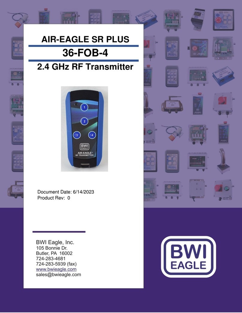
The AIR-EAGLE SRPLUS TX Is a handheld R.F. transmitter capable of
sending up to four unique digital commands to an Air-Eagle SR
Receiver located up to 600 feet away. This model is equipped with a
vibrating feedback that confirms to the user that the transmitted signal
has reached the receiver. Any number of transmitters and receivers
can be combined to create a medium-range radio frequency system
that operates hazardous or hard-to-reach equipment from safe,
convenient locations. Eight user-programmable frequencies allow
multiple systems to operate simultaneously in the same area without
interference. This transmitter will automatically go into “sleep” mode
when no buttons are being depressed on the unit to dramatically
extend battery life.
INITIAL OPERATION SET-UP
This transmitter comes factory set to frequency 1 and power level 4 (max
range of 600 feet). If you wish tochange the default settings, followthe
instructions forFREQUENCY PROGRAMMING AND POWER LEVEL
PROGRAMMING on page 2.
SPECIFICATIONS
Keypad
DurableSealed Membrane Keypad –
Eliminates Dust, Dirt and Moisture
Failures
Enclosure
ABS UL94 HB
Enclosure with
ring is rated IP54
*Not Waterproof
Protective Ring
SEBS (TPE)
Power Requirements
3.0 VDC
Battery Type
(2) 1.5V lithium each, size AAA, to
equal 3.0VDC nominal. ***For best
performance use ONLY Energizer
Brand Lithium Batteries
Battery Life(Active Usage)
Up to 6 months
Battery Life(Sleep Mode)
Up to 1 Year
Transmit Frequency
2.4GHz Spread Spectrum
RF Networks
Eight Independent Frequencies
RF Output Power
User Selectable from 1mW - 60 mW
Max Transmit Range
User-Selectable from 100 - 600 Feet
Note: Range figures are estimates, based on free-air terrain with limited sources of
interference. Actual range will vary based on transmitting power, orientation of
transmitter and receiver, height of transmitting antenna, height of receiving antenna,
weather conditions, interference sources in the area, and terrain between receiver and
transmitter, including, but not limited to, indoor and outdoor structures such as walls,
metal objects, trees, buildings, hills, and mountains.
Operating Temperature
-40oF to +185oF
Weight
Approx .22 lbs. (w/belt clip)
Dimensions –4.25” L x 2.68” W x .91” D
(note: belt clip adds .43” to depth)
CONTROLS & INDICATORS
TX LED
LED illuminates “RED” continuously while button is
depressed and unit is transmitting. When this LED blinks
briefly following a transmission, the battery needs to be
replaced. See Note #1
Note #1 –The low battery notification signals have been improvedto
providemore noticeable indications and to safely disable
communications BEFORE a low battery condition can corrupt internal
memory causing device failure. When a low battery is first detected,
the TX LED will blink several times after all buttons are released. If it is
possibleto replace the batteries now, please do so. If not, the operator
has approximately 15 more button activations. During this time, when
a button is depressed and held, the TX LED will blink SLOWLY. The
slow blinking will continue several more times after all buttons are
released. Transmissions are still being sent to the receiver during this
time. When a button is depressed and the TX LED is RAPIDLY
blinking, the RF output is disabled and NO signal will reach the
receiver. The batteries MUST NOW BE REPLACED to resume
normal functions.
Pushbuttons 1 thru 4
Transmits individual button RF codes to the
receiver
Vibrate Alert
Vibration confirming that signal has been
transmitted successfully
APPROVALS
United States (FCC)
MCQ-XBEE3
Canada (IC)
1846A-XBEE3
Europe (CE)
ETSI
AIR-EAGLE®SR PLUS
2.4 GHz RF Transmitter
MODEL 36-HH-4-VBR
FREQUENCY PROGRAMMING
At any time, you can check the current frequency setting by depressing
Buttons 3 & 4 simultaneously, for approximately 5 seconds, until the TX
LED is illuminated RED. Then release the buttons and watch as the TX
LED stays RED for about 8 seconds, goes out, then begins to blink. The
TX LED will blink RED one, two, three or four times for Frequencies 1 thru
4, or will blink GREEN one, two, three or four times for Frequencies 5 thru
8 accordingly. See table below for clarification.
LED Flashes:
Indicates Unit is Operating On:
RED –one time
Frequency 1
RED –two times
Frequency 2
RED –three times
Frequency 3
RED –four times
Frequency 4
GREEN –one time
Frequency 5
GREEN –two times
Frequency 6
GREEN –three times
Frequency 7
GREEN –four times
Frequency 8
To change the setting, follow these steps:
To select from Frequencies 1 thru 4:
1. Depress Buttons 3 & 4 simultaneously until the TX LED is
illuminated RED. (Approximately 5 seconds)
2. ReleaseButtons 3 & 4, then while the TX LED is still
illuminated RED, depress button #1 to select “Frequency 1” or
button #2 to select “Frequency 2” etc. If the transmit LED goes
out before you have selected a network, no settings will have
changed, and the LED will blink corresponding to the frequency
that the TX is currently set to. You must then begin again at
step 1 if you wish to change the current setting.
3. The TX LED will blink to confirm that your frequency selection
has been accepted, and then will go out. For instance, if you
have selected Frequency #1, the TX LED will blink RED once
to confirm. If you have selected Frequency #4, the TX LED
blinks RED four times to confirm.
To select from Frequencies 5 thru 8:
1. Depress Buttons 3 & 4 simultaneously until the TX LED is
illuminated GREEN. (Approximately 8 seconds)
2. ReleaseButtons 3 & 4, then while the TX LED is still
illuminated GREEN, depress button #1 to select “Frequency 5”
or button #2 to select “Frequency 6” etc. If the transmit LED
goes out before you have selected a network, no settings will
have changed, and the LED will blink corresponding to the
frequency that the TX is currently set to. You must then begin
again at step 1 if you wish tochange thecurrent setting.
3. The TX LED will blink to confirm that your frequency selection
has been accepted, and then will go out. For instance, if you
have selected Frequency #5, the TX LED will blink GREEN
once toconfirm. If you haveselected Frequency #6, the TX
LED blinks GREEN two times to confirm.
Programming is now complete, and the transmitter is active for normal
operation.
You may repeat the above procedure if you wish to change the frequency
at any time. See note* in SPECIFICATIONS.
POWER LEVEL PROGRAMMING
At any time, you can check the current power level by depressing Buttons
3 & 4 simultaneously, for approximately 11seconds, until the TX LED
starts blinking GREEN. Then release the buttons and watch as the TX
continues to blink for 10 seconds, goes out, then begins to blink again.
The TX LED will blink GREEN one, two, three or four times corresponding
the powerlevel setting (see table below)
LED Flashes:
Indicates Unit is Set To:
GREEN –one time
Power Level 1 –Approx 100 Ft Range
GREEN –two times
Power Level 2 –Approx 250 Ft Range
GREEN –three times
Power Level 3 –Approx 400 Ft Range
GREEN –four times
Power Level 4 –Approx 600 Ft Range
To change the setting, follow these steps:
To select a power level:
1. Depress Buttons 3 & 4 simultaneously until the TX LED is
blinking GREEN (Approximately 11 seconds)
2. ReleaseButtons 3 & 4, then while the TX LED is still blinking
GREEN, depress button #1 to select “Power Level 1” or button
#2 to select “Power Level 2” etc. If the transmit LED goes out
before you have selected a power level, no settings will have
changed, and the LED will blink corresponding to the power
levelthe TX is currently set to. Youmust then begin again at
step 1 if you wish to change the current setting.
3. The TX LED will blink to confirm that your power level selection
has been accepted, and then will go out. For instance, if you
have selected Power Level #1, the TX LED will blink GREEN
once to confirm. If you have selected Power Level #3, the TX
LED blinks GREENthree times to confirm.
LIMITED WARRANTY STATEMENT
BWI Eagle Inc. warrants theAir-Eagle Remote ControlSystem, if properly
used and installed, will be free from defects inmaterial and workmanship
for a period of 1 year after date of purchase. Said warranty to include the
repair or replacement of defective equipment. This warranty does not
cover damage due to external causes, including accident, problems with
electrical power, usage not in accordance with product instructions,
misuse, neglect, alteration, repair,improper installation, or improper
testing. This warranty also does not coverwater damage to any handheld
transmitter. This limited warranty, and any implied warranties that may
exist under state law, apply only to the original purchaser of the
equipment, and last only for as long as such purchaser continues to own
theequipment. This warranty replaces all otherwarranties, express or
implied including, but not limitedto, the implied warranties or
merchantability and fitness for a particular purpose. BWI Eagle makes no
express warranties beyond those stated here.BWI disclaims without
limitation, implied warranties of merchantability and fitness for a particular
purpose. Some jurisdictions do not allowthe exclusion of implied
warranties so this limitation may not apply to you. To obtain warranty
service, contact BWI Eagle for a return material authorization. When
returning equipment to BWI Eagle,the customer assumes the risk of
damage or loss during shipping and is responsible for the shipping costs
incurred.
DOCUMENT DATE: 03/08/2021 / PRODUCT REV. 12
105 Bonnie Drive
Butler, PA 16002
(724) 283-4681
Fax (724) 283-5939
www.bwieagle.com

Other BWI Eagle Transmitter manuals

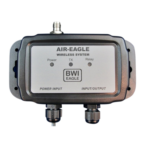
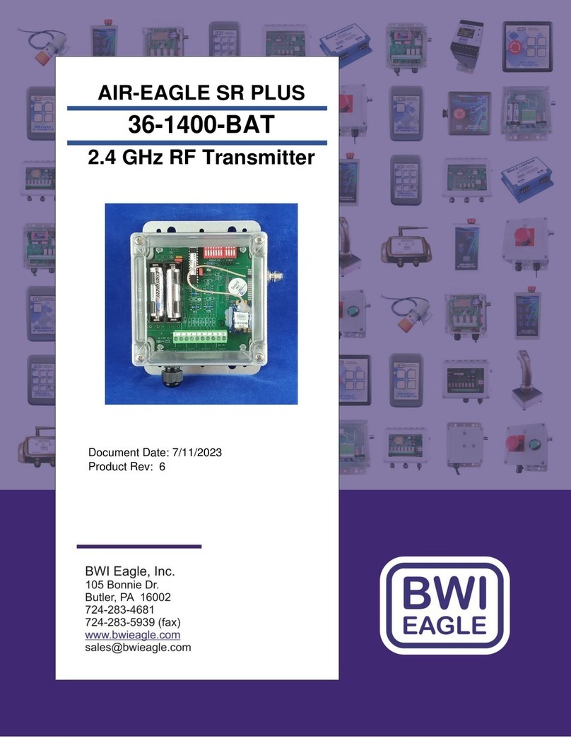
BWI Eagle AIR-EAGLE SR PLUS 36-1200-BAT Manual

BWI Eagle

BWI Eagle AIR-EAGLE SR PLUS 36-1200-BAT Manual

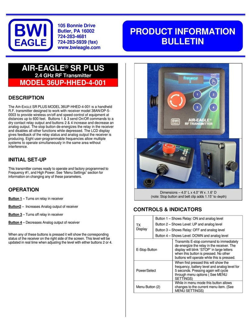
BWI Eagle AIR-EAGLE SR PLUS Manual

BWI Eagle

BWI Eagle AIR-EAGLE SR PLUS Manual

BWI Eagle AIR-EAGLE SR PLUS 36-HH-9 User manual

BWI Eagle

BWI Eagle AIR-EAGLE SR PLUS 36-HH-9 User manual

BWI Eagle AIR-EAGLE SR PLUS 36-1400-120VAC Manual

BWI Eagle

BWI Eagle AIR-EAGLE SR PLUS 36-1400-120VAC Manual

BWI Eagle AIR-EAGLE SR PLUS 36-1420-2B-120VAC Manual

BWI Eagle

BWI Eagle AIR-EAGLE SR PLUS 36-1420-2B-120VAC Manual

BWI Eagle AIR-EAGLE FM2 43-1100R1-DC Manual

BWI Eagle

BWI Eagle AIR-EAGLE FM2 43-1100R1-DC Manual

BWI Eagle AIR-EAGLE SR PLUS User manual

BWI Eagle

BWI Eagle AIR-EAGLE SR PLUS User manual

BWI Eagle AIR-EAGLE FM2 43-1000N4W-120VAC Manual

BWI Eagle

BWI Eagle AIR-EAGLE FM2 43-1000N4W-120VAC Manual

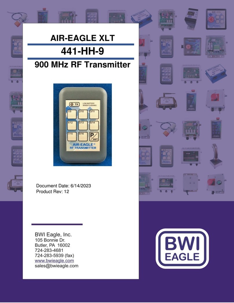
BWI Eagle AIR-EAGLE XLT Manual

BWI Eagle

BWI Eagle AIR-EAGLE XLT Manual

BWI Eagle 441-10100-AC Manual

BWI Eagle

BWI Eagle 441-10100-AC Manual

BWI Eagle AIR-EAGLE XLT User manual

BWI Eagle

BWI Eagle AIR-EAGLE XLT User manual

BWI Eagle AIR-EAGLE XLT 441-HH-1 User manual

BWI Eagle

BWI Eagle AIR-EAGLE XLT 441-HH-1 User manual

BWI Eagle 36-1400-DC User manual

BWI Eagle

BWI Eagle 36-1400-DC User manual

BWI Eagle AIR-EAGLE XLT PLUS 497-5100-CHx-DC Manual

BWI Eagle

BWI Eagle AIR-EAGLE XLT PLUS 497-5100-CHx-DC Manual

BWI Eagle 36-HHE-4 Manual

BWI Eagle

BWI Eagle 36-HHE-4 Manual

BWI Eagle AIR-EAGLE SR PLUS 36-HH-1 User manual

BWI Eagle

BWI Eagle AIR-EAGLE SR PLUS 36-HH-1 User manual

BWI Eagle AIR-EAGLE XLT PLUS 461-HH-1 Manual

BWI Eagle

BWI Eagle AIR-EAGLE XLT PLUS 461-HH-1 Manual

BWI Eagle AIR-EAGLE SR PLUS 36-HH-9-VBR Manual

BWI Eagle

BWI Eagle AIR-EAGLE SR PLUS 36-HH-9-VBR Manual

BWI Eagle AIR-EAGLE SR PLUS 36AN-1000-120VAC Manual

BWI Eagle

BWI Eagle AIR-EAGLE SR PLUS 36AN-1000-120VAC Manual

BWI Eagle AIR-EAGLE XLT Manual

BWI Eagle

BWI Eagle AIR-EAGLE XLT Manual

BWI Eagle AIR-EAGLE FM2 43-1100 Manual

BWI Eagle

BWI Eagle AIR-EAGLE FM2 43-1100 Manual

BWI Eagle AIR-EAGLE XLT Manual

BWI Eagle

BWI Eagle AIR-EAGLE XLT Manual

BWI Eagle AIR-EAGLE XLT 441AN/D-1000-120VAC Manual

BWI Eagle

BWI Eagle AIR-EAGLE XLT 441AN/D-1000-120VAC Manual

BWI Eagle AIR-EAGLE FM2 43-1150-120VAC Manual

BWI Eagle

BWI Eagle AIR-EAGLE FM2 43-1150-120VAC Manual

Popular Transmitter manuals by other brands

MEE AUDIO connect quick start guide

MEE AUDIO

MEE AUDIO connect quick start guide

SVS SHT-12 FS operating instructions

SVS

SVS SHT-12 FS operating instructions

SGM LEKTRA PTU05 quick start guide

SGM LEKTRA

SGM LEKTRA PTU05 quick start guide

Sona SM10 user guide

Sona

Sona SM10 user guide

Vaisala WXT510 user guide

Vaisala

Vaisala WXT510 user guide

Secure Wireless EV-F319 user manual

Secure Wireless

Secure Wireless EV-F319 user manual

Altinex TP316-101 user guide

Altinex

Altinex TP316-101 user guide

Kindermann Multishare 31 operating instructions

Kindermann

Kindermann Multishare 31 operating instructions

Speck IP-MDOCK user manual

Speck

Speck IP-MDOCK user manual

Zamel RNL-01 Manual instruction

Zamel

Zamel RNL-01 Manual instruction

Audio Authority FlexPort FPM-X Installation and operation guide

Audio Authority

Audio Authority FlexPort FPM-X Installation and operation guide

Emerson Rosemount 705 quick start guide

Emerson

Emerson Rosemount 705 quick start guide

Stingray STINGRAY 318LIPW V Series quick start guide

Stingray

Stingray STINGRAY 318LIPW V Series quick start guide

Soundcast iCast Transmitter owner's manual

Soundcast

Soundcast iCast Transmitter owner's manual

HK Instruments DPT-R8 Series installation instructions

HK Instruments

HK Instruments DPT-R8 Series installation instructions

WIKA DPT-20 operating instructions

WIKA

WIKA DPT-20 operating instructions

Intelix AVO-A4-WP110-EU installation manual

Intelix

Intelix AVO-A4-WP110-EU installation manual

Fisher-Rosemount 3095FT manual

Fisher-Rosemount

Fisher-Rosemount 3095FT manual

manuals.online logo
manuals.online logoBrands
  • About & Mission
  • Contact us
  • Privacy Policy
  • Terms and Conditions

Copyright 2025 Manuals.Online. All Rights Reserved.