Serai SR 24.85/24A F User manual

INSTALLATION MANUAL
SINCE 1965
ERAI
S
Gate Opener Department
MERCURIO 524A F SR 24.85/24A F KIT WITH ENCODER FOR SLIDING GATES UP TO 500 kg -24Vdc
CAUTION: READ THIS MANUAL CAREFULLY BEFORE
MAKING ANY CONNECTIONS, AND KEEP FOR
FUTURE REFERENCE
MERCURIO 524A H SR 24.84/24A MOTOR WITH CONTROL UNIT FOR SLIDING GATES UP TO 500 kg -24Vdc

SINCE 1965
Page 2/16
MERCURIO/524A I E
Thank you for choosing a SERAI ELETTRONICA product, which we are confident will perform to your requirements.
Please be advised that you are about to fit a system classified as “a power-operated drive designed to move automatic
gates and doors in commercial or residential buildings accessed by vehicles and persons”, and, as such, the system
must be considered potentially hazardous. By law, you are responsible for rendering this equipment as “safe” as is
reasonably possible.
Installation and maintenance of equipment of this kind must therefore be carried out by skilled, qualified and trained
personnel, working in a professional manner, as provided for by law n. 37/08 and subsequent amendments and
supplements thereto. The law in question prohibits the construction of these types of systems by non-qualified
personnel.
SERAI manufacturing complies with the following legislation:
Applicable directives for the CE marking:
Machines: 2006/42/EEC
Low voltage: 73/23/EEC + 93/68/EEC
Electromagnetic compatibility: 2004/108/EEC
General applicable standards:
Electrical safety: IEC EN60335-1 + IEC EN60335-2-103
Electromagnetic compatibility - emissions: IEC EN61000-6-3
Electromagnetic compatibility - immunity: IEC EN61000-6-1
Apart from the legislation mentioned above, you are also reminded to comply with the following standards during the
installation phase.
General applicable standards:
Safety of electrical systems in non-specialised environments: CEI 64-8 V2
Specific product standards applicable:
Safety in the use of power-operated doors requirements: UNI EN12453
Safety in the use of power-operated doors testing methods: UNI EN12445
SERAI products enable users to build systems which comply with these standards. This is extremely important as
THE INSTALLER IS LIABLE FOR THE SYSTEM AND FOR ENSURING ITS OPERATION COMPLIES WITH
LEGAL PROVISIONS.
This handbook must be read in full, at least once, before proceeding with the installation of the various parts
of the system.
The installation of the mechanical end stops for gate opening and closure is necessary for system safety
purposes and therefore this operation must be performed before proceeding with the installation of the
control unit.
!

1.2 WIRING EXAMPLE FOR KIT CONTENTS
CABLE FOR TX 2 x 0,5 mm²
KEY CABLE 3 x 0,5 mm²
POWER SUPPLY CABLE
3 x 1,5 mm²
CABLE FOR LIGHT + ANTENNA
2 x 0,75 mm² + RG58
CHAPTER 1: GENERAL INFORMATION
1.1 KIT CONTENTS
1. a
2. a- Base plate
b- Bolts
c- Nuts
d- Washers
3. a- End stop sliding plates
b- M6 grub screws for fastening sliding
plates
- Motor models: MT/524A
b- Encoder system
c- CR/42/24 electronic control unit
d- Release keys
e- M8 grub screws for motor levelling
4. M/10 electric key
5. Pair of P/10 photocells with plugs
6. OG/62 mini transmitter (OG/28 on the H version)
7. Flashing light with built-in antenna RZ/24 F
8. RZ/99 L-shaped holder
CAUTION: Accessories 4-5-7-8 are not
featured in the H versions,
i.e. motors equipped with
control unit
d
a
c
b
2
a
b
4567
CABLE FOR RX 4 x 0,5 mm²
4
6
1 2
3
3
8
3
230 V~
Page 3/16
Advice for wiring up in non-specialised environments.
1. Fit an omnipolar switch upstream of the system, choosing one with a gap of at least 3 mm between the contacts. Or,
alternatively, use a 10Amagnetothermic switch.
2. When making the connections (using any type of connector), ensure the system is disconnected from the power
supply, i.e. that the main switch is in the “open” position (“0” symbol). The control unit, in particular, must never be
connected to the power supply either during the wiring up, or when fitting any expansion cards.
3. The following cables must be used for installation of the system:
22
- for the control unit and motor power supplies: 1.5 mm section for lengths of up to 19m, 2.5 mm section for
lengths of up to 31 m,
22
- for the flashing light: 0.75 mm section for lengths of up to 3 m, 1.5 mm section for lengths of up to 19 m.
- for the low voltage and current lines (e.g. For the photocells, control buttons, electromechanical key, sensitive
22
edges and other safety devices): 0.5 mm section for lengths of up to 50 m, 0.75 mm section for lengths of up to
100 m.
4. Wire up the earth connection in compliance with legal provisions.
5
5
7
8
SINCE 1965
a
b
d
1
e
c
MERCURIO/524A I E
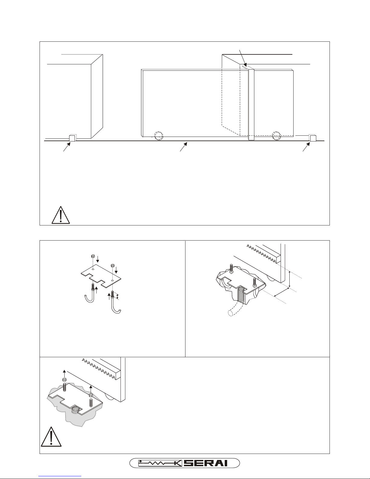
MECHANICAL END STOP
(CLOSURE)
MECHANICAL END STOP
(OPENING)
GROUND-ANCHORED RAIL
(REINFORCED
CONCRETE GROUND)
SUPPORT RAILS
CHAPTER 2: MOTOR INSTALLATION
2.1 BEFORE STARTING
Check that the gate is equipped with sturdy support rails
Check that the rail is anchored securely to the ground
Fit two sturdy mechanical stops at the two ends of the rail
Check that the gate runs smoothly along the rail
The installation of the mechanical end stops for gate opening and closure is necessary for
system safety purposes and therefore this operation must be performed before proceeding with
the installation of the control unit.
2.2 INSTALLING THE BASE PLATE
35 mm
2.2A
Screw the two nuts onto the bolts, until they are
positioned 35 mm from the end of the thread
Fit the J bolts through the holes in the base plate
Screw the other two nuts onto the J bolts without
tightening
2.2B
Dig a hole and place the base plate (fastened to the
bolts) inside it, along with the cable carrier hose
Position the base plate at the heights specified,
fastening it so that it stays flat
95 mm
75 mm
2.2C
Cast concrete to secure the unit to the ground, ensuring all the
base plate parts are kept clean and the two nuts are out of the
concrete completely.
Wait for the concrete to harden, then remove the two nuts
CAUTION:
If the motor is located in an area prone to flooding, the base plate must be positioned high
enough to stop the water reaching the motor
Page 4/16
SINCE 1965
MERCURIO/524A I E

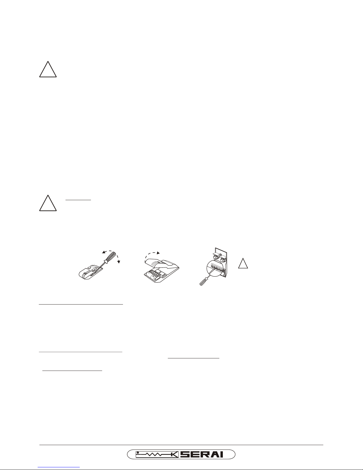
2.3 OPENING THE MOTOR UNIT
Remove the fastening screws on the side of the
unit
Remove the motor cover
Remove the plastic casing from the motor unit
2.4 MOTOR POSITIONING
2.4 A
Screw the 4 grub screws into the relevant housing
Position the motor on the base plate, inserting the threaded part of the J bolts
through the slots in the base
Level the motor by adjusting the grub screws
Fit the washers onto the bolts and screw on the 2 nuts without tightening them
completely. These bolts must not be secured until the tooth rack is in its final
position
2.5 RELEASING THE MOTOR
2.4 B
Cut small holes in the rubber seals, so that they grip each of the cables properly.If this operation is not carried out
and insects get inside the unit, a short circuit may occur, causing irreparable damage to the ECU.
Fit the release key into the lock on the front panel of the motor unit and turn it anticlockwise by a half turn
Push the release flap hard downwards until the release mechanism is triggered
Page 5/16
SINCE 1965
GRUB SCREWS
NUTS
WASHER
1/2
MERCURIO/524A I E
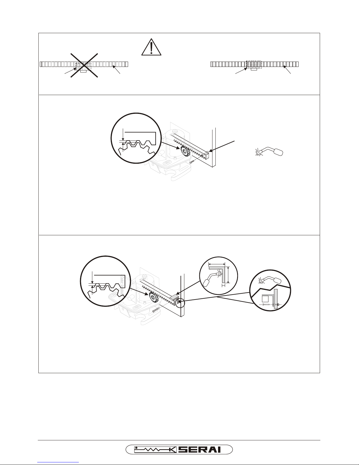
2.6 B
Lay the 1 m tooth rack bars in a line so that the entire distance of the “gate + motor + sliding plates” is covered; if
necessary cut the last bar to size
Weld the spacers supplied with the tooth rack to the gate in position with the slot holes
Fasten the tooth rack to the spacers and secure with the bolts supplied
Once the operation is complete, adjust the vertical distance between the pinion and the tooth rack, using the slotted
holes on the tooth rack, so that - when the gate is slid manually - the clearance is kept constant at approximately
2 mm
2.6 TOOTH RACK INSTALLATION
2.6 A CAUTION: check that the pinion engages with the tooth
rack along the entire width of the tooth
NO YES
PINIONTOOTH RACKPINION TOOTH RACK
M/14 STEEL TOOTH RACK INSTALLATION
2.6 C
Lay the 2 m tooth rack bars in a line so that the entire distance of the “gate + motor + sliding plates” is covered; if
necessary cut the last bar to size
Weld the tooth rack to a steel corner piece (dimensions: 40x40x5 mm)
Weld or screw the corner piece onto the gate
Once the operation is complete, slide the gate manually and check that there is a constant clearance of
approximately 2 mm between the pinion and the tooth rack
M/01 STEEL TOOTH RACK INSTALLATION
40mm
40mm
5 mm
SPACER TO WELD ON
Page 6/16
SINCE 1965
CLEARANCE
APPROX.
2 mm
CLEARANCE
APPROX.
2 mm
MERCURIO/524A I E
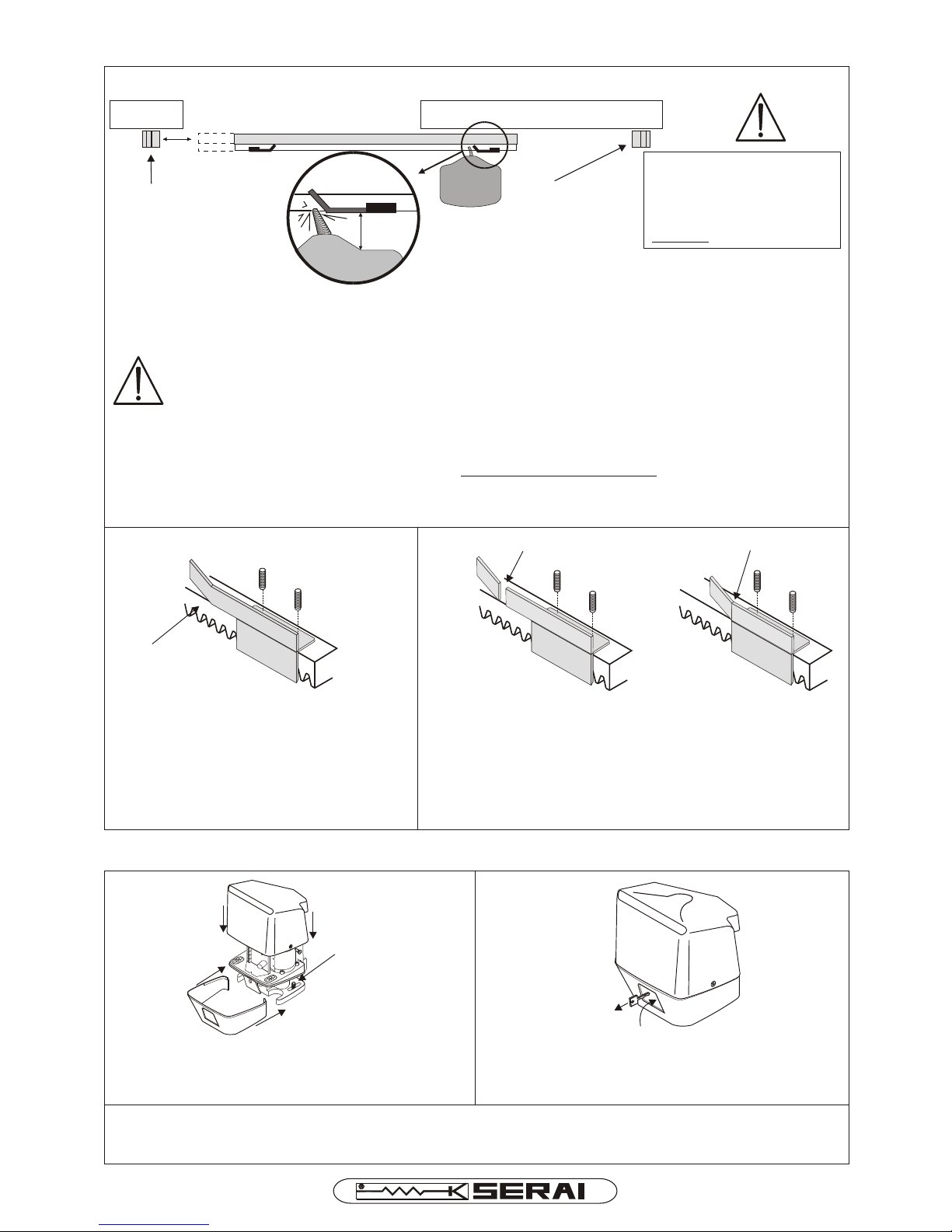
2.7 INSTALLATION OF THE END STOP SLIDING PLATES
2.7A POSITIONING
CLICK!
MOTOR
MECHANICAL
END STOP
(OPENING)
5 cm
MECHANICAL
END STOP
(CLOSURE)
Slide the gate manually until it is approximately 5 cm away from the mechanical end stop
Position the sliding plate so that it controls the microswitch actuator spring; you should hear a click as the
microswitch flips when the sliding plate passes it
CAUTION:
- To guarantee correct limit switch operation, ensure there is a distance of 30 mm (tolerance: ± 5 mm)
between the side of the motor and the sliding plate. A gap of over 35 mm may cause the gate to jam
open or closed. A gap of under 25 mm may cause breakage of the limit switch control spring.
- The end stop sliding plates must be set (taking into account inertia and changes in
temperature) so that the gate never ends up resting on the mechanical end stops during
opening and closure. If this occurs, the FLAP COULD GET BROKEN during the release
operation. Because of seasonal temperature differences, we recommend you check this in
both summer and winter.
CAUTION:
For safety reasons, an
end stop must be fitted for
both the closure and
opening movements
2.8 DEFINITIVE MOTOR FASTENING
2.8 A
Tighten the nuts on the J bolts fully
Place the lower plastic casing and the motor cover
back in position, fastening the latter with the two
side screws
2.8 B
Lock the motor manually by closing the release flap
and removing the key from the lock cylinder
2.8 C
Open or close the gate a few cm by hand until the stop pinion locks
MAX 35 mm
MIN 25 mm
TIGHTEN
FULLY
Page 7/16
SINCE 1965
MERCURIO/524A I E
2.7B FASTENING
TOOTH RACK
Once the correct position has been
found, fasten the sliding plate to the
tooth rack using the two M6 grub
screws supplied
Repeat the operation during opening
If need be, it is possible to shorten the slide plates
cutting and blending the front side
CUT BEND

CHAPTER 3: ELECTRONIC CONTROL UNIT
3.1 CR/42/24 WIRING DIAGRAM
Page 8/16
PHOTOCELL
FOR CLOSURE
RECEIVER
TRANSMITTER
PEDESTRIAN
OPEN/CLOSE
SENSITIVE EDGE
CLOSURE LIMIT SWITCH
OPENING LIMIT SWITCH
DISCONNECT THE POWER
SUPPLY BEFORE WORKING
ON THE WIRING
GATE OPEN INDICATOR
LIGHT 24V MAX 50mA
FLASHING LIGHT
24V MAX 25W
SINCE 1965
MERCURIO/524A I E
NORMAL SPEED
Trimmer for motor speed adjustment
during normal working phase
3 - 4 Input for power supply of electronic board 20Vac via a toroidal
transformer (pre-wired red green/orange cables)
11 - 12
7 - 8
13 - 14
15
16
18
20
PHOTOCELL
FOR OPENING
OR SENSITIVE
EDGE
23
With dip SW2 OFF: input for photocell active during both opening and closure
(NC contact): if obscured during opening, the gate stops moving, but starts
again as soon as the photocell is clear; in closure it reverses the motion
With dip SW2 ON: input sensitive edge (NC contact): both in opening and
closure the gate reverses the motion by 10 cm
21 -17
FUSES:
F3 = T16A 250V
-power supply control unit-
F4 = F2A 250V
-main-
F1 = T1,6A 250V
-low voltage protection-
F2 = T16A 250V
-battery fuse-
-delayed-
-delayed-
-delayed-
+
-
NC
NO
NC
STOP
NO
NC
NC
NC
22
12
9
ANTENNA
GND
(SHEATH)
OPEN
CLOSE
1
2
3
4
5
6
7
8
F1F1
F2F2
25
24
START
PED
STOP
FOTO
FCA
FCC
DL8
+
-
ENCODER
PAUSA
LAVORO PROG
F3F3
ONON
SW1
SW2
SOG 4
FOTO-1
+
-
VELOCITA'
REGIME
VELOCITA'
RALLENTAMENTO
13
10
11
14
15
16
17
18
19
20
21
22
23
+
-
Batterie
12Vdc 1,2Ah
OPTIONAL
230V~ ±10%
50/60Hz
F
N
1A SLOW-ACTING
MAINS FUSE
F4
BROWN
BLUE
+
-
RED
GREEN or ORANGE
1 - 2 BATTERIES Input for backup power supply for n. 2 batteries (in series) 12Vdc 1,2 Ah
(Type SERAI BT/14) battery charger included, 1 -, 2 +
5 - 6
9 - 10 INDICATOR LIGHT Gate open indicator light output 24Vdc max 50mA ( , 10 -)9 +
19 PHOTOCELL
FOR CLOSURE
Input for photocell active only in closure (NC contact): in closure the gate
reverses the motion
SLOW-DOWN SPEED
Trimmer for motor speed adjustment
during slow-down phase
+
-
BLACK (do not use)
YELLOW (do not use)
*
*
2425
+
-
+
-
24 - 25
DL9
Batterie
12Vdc 1,2Ah
OPTIONAL
SOG/4A
Connector for any SOG/4A receiver
cards
ENCODER
Connector for encoder wiring
(If featured)
Sw1
Microswitches for control unit setting
Sw2
Microswitches for control unit setting
PROG
Button to enter programming mode
PAUSE
Button for gate open pause
Programming
WORK
Work programming button
DESCRIPTIONTERMINALS CONNECTIONS
Courtesy light output. V
Active for 90 seconds from STOP
oltage free relay contact - 10A 250Vac-
Flashing light power supply output -max 25W- SERAI RZ/24F
FLASHING LIGHT
COURTESY LIGHT
MOTOR Motor power supply 24Vdc output (5 = Closure 6 = Opening)
POWER SUPPLY
POWER SUPPLY
PHOTOCELLS Power supply output 24Vdc (13=+, 14=-)for photocells
Opening limit switch (NC contact when gate is in an intermediate
position)
Closure limit switch (NC contact when gate is in an intermediate
position)
LIMIT SWITCH
(OPENING)
LIMIT SWITCH
(CLOSURE)
STOP
CONTROL
Stop control input (NC contact). When pressed, this control locks
out motor operation; if pressed during the gate open pause time,
it overrides the automatic reclosure
Input common terminals
INPUT
COMMON
PEDESTRIAN
CONTROL
OPEN/CLOSE
CONTROL
Input for antenna connection for built-in receiver (24=ANTENNA,
25=GND/ )sheath
BUILT-IN
RECEIVER
ANTENNA
Pedestrian control input (NO contact). When pressed, this control
opens the gate by approx. 1 metre
N.B. This function can be modified as described in "modify controls".
Open/close control input (NO contact) - this controls gate opening
and closure in the step-step mode
N.B. This function can be modified as described in "modify controls".
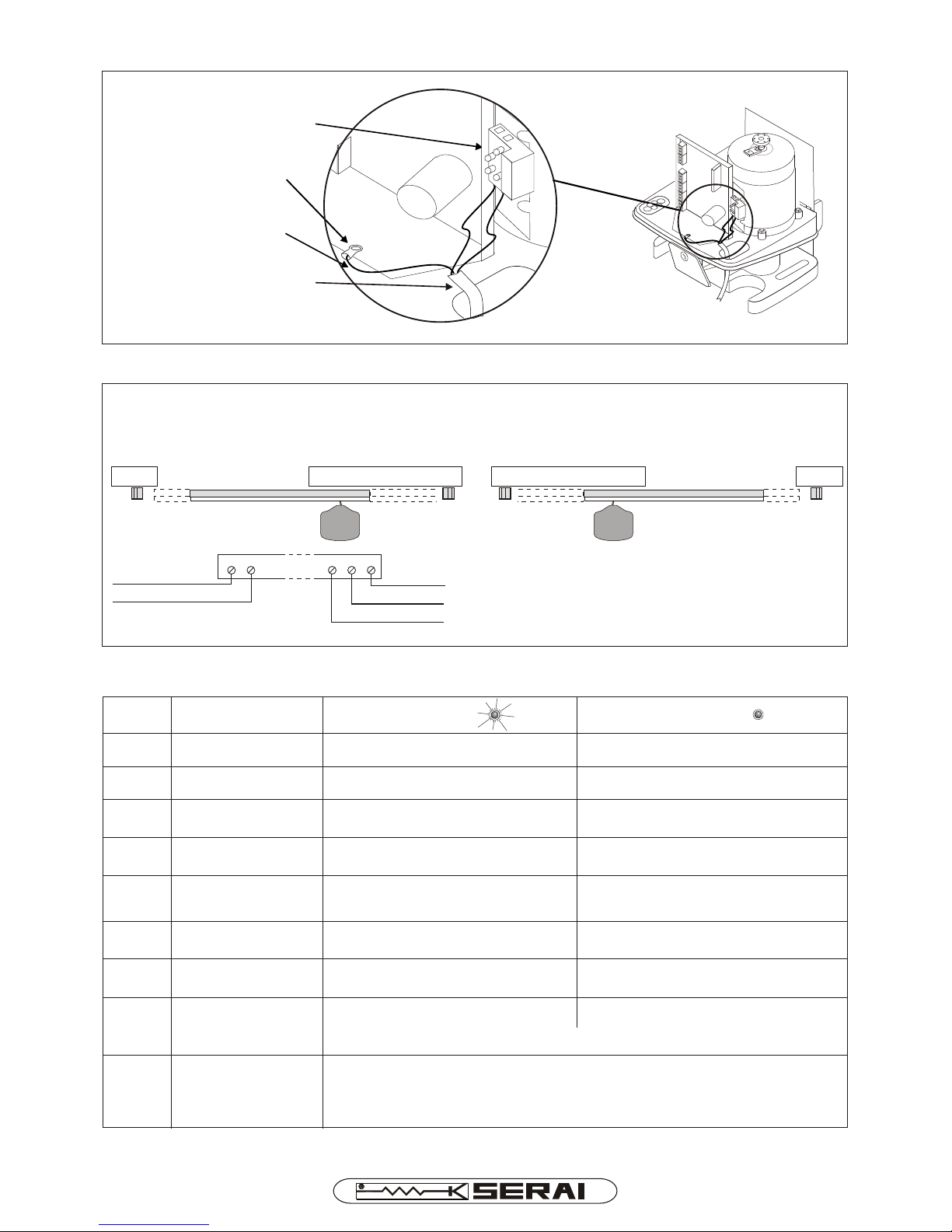
3.2 EARTH CONNECTION
Page 9/16
3.3 MOTOR CONNECTIONS
The connections differ depending on whether the motor (viewed from inside the gate) is positioned on the right
(factory setup) or on the left.
MOTOR ON THE RIGHT (FACTORY SETUP) MOTOR ON THE LEFT
To connect the motor on the left-hand side of the
gate, swap the following connections:
5 with 6
15 with 16
CR/42/24
5 6
15 16 17
BLACK
BLUE
BROWN
CLOSE
OPEN
3.4 LED SIGNALS
LED
FCC
FCA
FOTO
STOP
PED
START
ON OFF
FUNCTION
Opening limit switch
Closure limit switch
Photocell
STOP button
PEDESTRIAN button
Open/Close button
Photocell clear
Stop button in normal status
Pedestrian button pressed
Open/Close button pressed
Gate close or in intermediate
position (NC contact)
Gate completely closed
(NO contact)
Gate completely open
(NO contact)
Photocell obscured
(obstacle present)
Stop button pressed
Pedestrian button in normal status
Open/Close button in normal status
DL8 Programming/Test
- Flashing light to show programming mode has been accessed
- High frequency flashing light to indicate faults encountered during the
motor control test
DL9 Encoder During gate movement, indicates encoder pulse reception
POWER SUPPLY
CABLE
230 V~
YELLOW/GREEN
CABLE
MOTOR
CONNECTION
TERMINAL
Gate open or in intermediate
position (NC contact)
SINCE 1965
MERCURIO/524A I E
CONNECTION TERMINAL
WITH FUSE HOLDER
Sensitive edge: in normal status
FOTO-1 Opening photocell
or sensitive edge
Photocell clear Photocell obscured
Sensitive edge: pressed
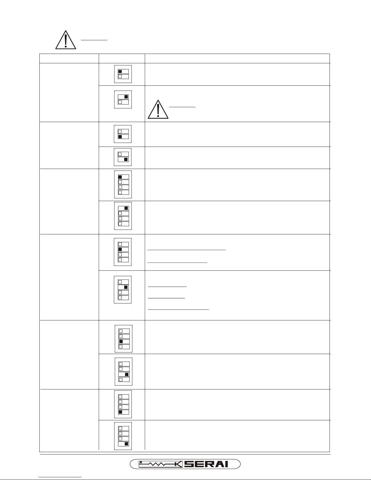
3.5 SETTINGS OF EACH MICROSWITCH
OPERATION SETTING
Page 10/16
Pre-flashing enabled: the flashing light switches on 3 seconds prior to
the gate opening.
ENABLE/DISABLE
FLASHING LIGHT
PRE-FLASHING
Step-step function disabled
During opening: if an OPEN/CLOSE command is sent, it is ignored
and the gate goes on opening.
During closure: if an OPEN/CLOSE command is sent, gate motion
stops for a few seconds and then the gate starts opening again.
During open gate pause: overrides the pause time, making the gate
close immediately.
ENABLE/DISABLE
STEP-STEP
OPERATION MODE
IMPACT
WITH OBSTACLE Force limitation deactivated: impact with an obstacle is not detected
and the motor goes on driving the gate.
CAUTION: If the microswitch programming is modified, the new settings are rendered
Active by switching the control unit off then on again.
DESCRIPTION OF OPERATION
CAUTION: with the force limitation feature deactivated,
other safety devices must be adopted (e.g. sensitive edge),
which must be compliant with regulations in force.
Input for photocell active during both closure and opening: if the
photocell is obscured during opening, the gate stops moving, but starts
again as soon as the photocell is clear; if the photocell is obscured
during closure, the gate will stop moving, and then start opening again.
Force limitation activated: in the event of an impact with an obstacle,
whether during opening or closure, an encoder system detects the
impact, stops the gate and then reverses it by 10cm see Page 12.
Pre-flashing disabled: the flashing light switches on at the same time
as the gate starts opening.
SINCE 1965
MERCURIO/524A I E
1 2
ON
SW2
1 2 3 4
ON
SW1
1 2 3 4
ON
SW1
CLAMP 18
OPERATION
MODE
1 2 3 4
ON
SW1
Input sensitive edge: both in closure and opening the gate reverses
the motion by 10 cm
1 2 3 4
ON
SW1
1 2
ON
SW2
SLOW-DOWN
ENABLED
1 2
ON
SW2
1 2
ON
SW2
1 2 3 4
ON
SW1
1 2 3 4
ON
SW1
1 2 3 4
ON
SW1
1 2 3 4
ON
SW1
Step-step function enabled
during the opening and closure: all command open/close are executed
according to what settled with dip1 SW1
during open gate pause: a command open/close overrides the pause
time, making the gate close immediately
STEP-STEP
OPERATION
MODE TYPE
The commands open/close set the sequence
OPEN/STOP/CLOSE/OPEN
The commands open/close set the sequence
OPEN/STOP/CLOSE/STOP/OPEN
Slow-down activated
Slow-down deactivated

Page 11/16
3.8 OBSTACLE IMPACT CONTROL AND MOTOR FORCE ADJUSTMENT
With the SW2 microswitch 1 in the OFF status, obstacle impact is detected (during both the opening and closure
manoeuvres) by the encoder system which stops the gate moving and then reverses it by approx. 10 cm.
This control is switched off with the SW2 microswitch 1 in the ON status; in this case, other safety systems
compliant with regulations in force (e.g. sensitive edges) must be adopted. This is extremely important as THE
INSTALLER IS LIABLE FOR THE SYSTEM AND FOR ENSURING ITS OPERATION COMPLIES WITH LEGAL
PROVISIONS
The
impact force is adjusted using the VELOCITA REGIME potentiometer during the normal working phase and using
the VELOCITA RALLENTAMENTO potentiometer during the slow-down phase; the adjustments must be performed
in compliance with the regulations in force.
.
3.9 CR/42 CONTROL UNIT TECHNICAL SPECIFICATIONS
CAUTION
The considerable differences in
temperature between summer and winter
can cause differing rates of expansion in
all materials, including those used for
manufacturing our motors. That is why we
recommend you check the impact force
setting at the start of winter and summer.
SINCE 1965
MERCURIO/524A I E
3.6 BATTERIES BACKUP (OPTIONAL)
It is possible to connect inside the MERCURIO 524 A two backup batteries
(2Vdc 1,2 Ah SERAI BT/14), in order to enable the automation to work for
a short period also in case of power failure. The batteries have to be
connected in series (see Picture aside); the positive cable has to be
connected to the clamp 2 (BATTERY +) and the negative cable to the
clamp 1 (BATTERY )
3.7 MOTOR WORKING WITHOUT ENCODER
The control panel CR/42/24 has been conceived to work also without ENCODER, therefore can be used also
with other kind of motors 24Vdc. The control panel can be enabled to work without encoder acting on the micro
switches SW1 and SW2; in this case it is not necessary any programming, being the working phase between the
limit switches.
1 2
ON
1 2 3 4
ON
SW2 SW1
SW2 micro switch 1 in ON status
SW1 micro switch 4 in ON status
2 batteries 12Vdc 1,2Ah (SERAI BT/14)
OPTIONAL
CAUTION: working without ENCODER,
the force limitation is disabled, other
safety devices must be adopted (e.g.
sensitive edge) which must be compliant
with regulation in force.
+
+
--
12
9
1
2
3
4
5
6
7
8
F1F1
F2F2
25
24
START
PED
STOP
FOTO
FCA
FCC
DL8
+
-
ENCODER
PAUSA
LAVORO PROG
F3F3
ONON
SW1
SW2
SOG 4
FOTO-1
+
-
VELOCITA'
REGIME
VELOCITA'
RALLENTAMENTO
13
10
11
14
15
16
17
18
19
20
21
22
23 DL9
Power supply: 230Vac ±10% 50/60Hz - 230/20Vac, 100VA-
24Vdc ÷ 25% - 12Vdc, 1,2Ah-
: 230/20 Vca, 100VA
Motor power supply: 1 motor 24Vdc, 1,5A
Accessories power supply: 24Vdc, 500mA
Flashing light power supply: 24Vdc, max 25W
Gate open indicator light power supply: 24Vdc, max 50mA
Courtesy light: 90s permanently lit from when the gate stops
Motor work time maximum safe level: 300s
Pause time setting: from 0 to 120s
Operating temperature: -20°C ÷ +60°C
Dimensions and weight: 112x151x50mm, 170g
From mains with transformer
from N. 2 optional batteries
Power supply transformer
3.10 CR/42/24 CONTROL UNIT PROGRAMMING
With the control unit powered, release the gate, open it approx. 2 metres, then relock it. Press the PROG,
button once; the DL8 LED will start flashing, indicating that the control unit has entered the programming phase.
The next section deals with the CR/42/24 control unit programming.
It is important to follow the programming step by step; in the event of errors during this stage, a new programming
session must be performed, in which case the new data will replace the previous data.
To quit an incorrect programming session, switch the control unit off then on again.
Before proceeding with the programming, check that the system is equipped with all the electrical and safety devices
(buttons, photocells, flashing lights, etc.) and that they are all connected. Ensure they all operate correctly, i.e.:
All the indicator LEDs for the NC inputs (stop, photocell, limit switch) are lit;
All the indicator LEDs for the NO inputs (open/close, pedestrian) are off.
In the event of faults, ascertain and remove the cause.
CAUTION: ANY UNUSED NORMALLY CLOSED (NC) INPUTS MUST BE JUMPERED.
3.10.1 PROGRAMMING THE WORK TIMES AND IMPACT FORCE SETTING MANUALLY
The deceleration point is set by the installer and can be cut out
Press the WORK button once to start the closure manoeuvre. The sliding gate will begin the closure manoeuvre
with a starting thrust and will then decelerate and continue at a slow pace.
During slowing down, adjust the VELOCITA RALLENTAMENTO trimmer to set the force that will be applied
during deceleration (in the event of impact with an obstacle).
Once the closure manoeuvre is complete and the FCC (closure limit switch) LED is off, press the LAVORO
(Operation) button once: the gate will start opening.
During the opening manoeuvre, adjust the VELOCITA REGIME trimmer to set the force that will be applied
during il normale funzioanmento (in the event of impact with an obstacle).
Before the gate completes the opening manoeuvre, press the LAVORO (Operation) button (we recommend
doing this when it is 50 cm away from the end stop). This sets the desired deceleration start point, and the gate
will start the deceleration phase.
N.B. If you wish to deactivate deceleration during normal operation cycles, skip this step and dip4 SW1 ON.
As soon as the gate has completed the opening manoeuvre, the work cycle is acquired, as is the deceleration
point, if set. After a few seconds, the closure manoeuvre starts, and the programmed deceleration is applied.
When the gate reaches the closure limit switches (FCC LED off), the control unit automatically quits the
programming phase and switches to standard operation mode.
CAUTION: If one or more parameters are altered, programming must be repeated
from the beginning.
Page 12/16
3.10.2 GATE OPEN PAUSE TIME PROGRAMMING
With the control unit powered and the gate closed (closure limit switch FCC - LED off), press the PROG,
button once; the DL8 LED will start flashing, indicating that the card has entered the Programming phase.
Press the PAUSA (Pause) button once, keeping it pressed until the flashing light comes on; the control unit will
start the gate open pause count, which is indicated by the light flashing intermittently.
Once the desired time has lapsed, press the PAUSA (Pause) button again; the control unit will automatically
store the amount of time between the two times the PAUSA (Pause) button was pressed. It then quits the
programming phase and switches to standard operation mode. If the PAUSA (Pause) button is not pressed a
second time within 120 s, the control unit quits the programming, memorising the maximum time as 120 s.
ACTIVATING AUTOMATIC RECLOSURE (max time settable: 120 s)
With the control unit powered and the gate closed (closure limit switch FCC - LED off), press the PROG button
once; the DL8 LED will start flashing, indicating that the card has entered the programming phase.
Press the PAUSA (Pause) button and keep it pressed until the DL8 LED switches off.The control unit quits the
programming phase and switches to standard operation mode.This operation deactivates the automatic
reclosure function.
DEACTIVATING AUTOMATIC RECLOSURE
SINCE 1965
MERCURIO/524A I E
CONTROLS MODIFICATION (available starting from model A009-11, id. code on the micro)
It is possible to modify the functioning of the 22 and 23 inputs in this way:
- Input 23 functions as "START": with control unit off, press and hold keys "PROGR" and "WORK" simultaneously
and apply power supply.
- Input 23 functions as "CLOSE only": with control unit off, press and hold keys "PROGR" and "PAUSE"
simultaneously and apply power supply.
- Input 22 functions as "PEDESTRIAN": with control unit off, press and hold keys "WORK" and "PAUSE"
simultaneously and apply power supply.
- Input 22 functions as "OPEN only": with control unit off, press and hold keys "PAUSE" and "WORK" and
"PROGR" simultaneously and apply power supply.
Page 13/16
CHAPTER 4: MINI TRANSMITTER CODE LEARNING
The electronic card incorporates a 433.92 MHz 2-channel radio receiver which allows remote gate control via either
the OG/02 and OG/04 series microswitch-operated mini transmitters or the self-learning mini transmitters from the
following series: OG/62, OG/64, OG/28, OG/48, OG/52, OG/54, OG/82/1 and OG/84. Both channels are used
solely for gate control; more specifically, channel 1 of the radio receiver serves for the open/close function, while
channel 2 is used for the pedestrian function.
!CAUTION: - a mini transmitter must be programmed before it is used.
- the maximum number of codes that can be stored is 32 for the open/close control +
32 for the pedestrian control (no other combinations, e.g. 40 open/close + 24
pedestrian etc, are possible). Let's have a look at two examples of storable codes:
- example A: 32 self-learning mini transmitters from the following series: OG/62,
OG/64, OG/28, OG/48, OG/52, OG/54, OG/82/1 and OG/84 as the open/close
control (e.g. left-hand button) + 32 self-learning mini transmitters from the
following series: OG/62, OG/64, OG/28, OG/48, OG/52, OG/54, OG/82/1
and OG/84 as the pedestrian control (e.g. right-hand button)
- example B: 31 self-learning mini transmitters from the following series:
OG/62, OG/64, OG/28, OG/48, OG/52, OG/54, OG/82/1 and OG/84 as the
open/close control (e.g. left-hand button) + 1 OG/02 or OG/04 series
microswitch-operated mini transmitter as the open/close control (there is
no need to store the other OG/02 and OG/04 transmitters, simply set the
microswitches in the same sequence as the one already stored) + 31 self-
learning mini transmitters from the following series: OG/62, OG/64,
OG/28, OG/48, OG/52, OG/54, OG/82/1 and OG/84 as the pedestrian control
(e.g. the right-hand button) + 1 OG/02 or OG/04 microswitch-operated mini
transmitter as pedestrian control (there is no need to store the other OG/02
and OG/04 transmitters, simply set the microswitches in the same sequence
as the one already stored)
!
123 4 56 78910
12 3 456 78910
!
MODIFYING THE FACTORY-SET
CONFIGURATION TO PREVENT
UNWANTED COMMANDS
MICROSWITCH CONFIGURATION (FOR OG/02 AND OG/04 MINI TRANSMITTERS ONLY)
These instructions only apply if the OG/02 and OG/04 series microswitchoperated mini transmitters are fitted.
Before performing the code learning procedure on the receiver, the factory-set configuration of the microswitches
must be modified to prevent unwanted commands
CAUTION: before proceeding with the mini transmitter programming or clearing phase,
disconnect the antenna to prevent the receiver from acquiring other signals during these
phases which could impair automation operation. Reconnect the antenna once the procedures
are complete.
4.2 CLEARING OF STORED CODES
All the radio codes stored in the memory can be cleared by pressing the PROG and PAUSA keys AT THE SAME
TIME, and keeping them pressed until the DL8 LED switches off (approx. 10 s) without sending any radio codes
during this time. This operation clears all the codes associated to both the open/close and the pedestrian control.
OPEN/CLOSE CODE LEARNING
- With the control unit powered and the gate closed, press the PROG key once to enter the programming phase.
The DL8 LED starts flashing to indicate that the control unit is in the programming mode.
- Press the button on the mini transmitter (the left-hand one, for example) which you wish to serve as the
open/close control, and keep it pressed until the DL8 LED switches off. The control unit stores the radio code
received and automatically quits the programming phase, switching to the standard operation mode.
- Repeat the procedure if several mini transmitters need to be stored.
PEDESTRIAN CODE LEARNING
- With the control unit powered and the gate closed, press and hold down the PROG key to enter the programming
phase. The DL8 LED starts flashing to indicate that the control unit is in the programming mode.
- Keeping PROG pressed, push the button on the mini transmitter (the right-hand one, for example) which you wish
to serve as the pedestrian control, and keep the two buttons pressed until the DL8 LED switches off. The control
unit stores the radio code received and automatically quits the programming phase, switching to the standard
operation mode.
- Repeat the procedure if several mini transmitters have to be stored.
4.1 MINI TRANSMITTER PROGRAMMING PROCEDURE
SINCE 1965
MERCURIO/524A I E
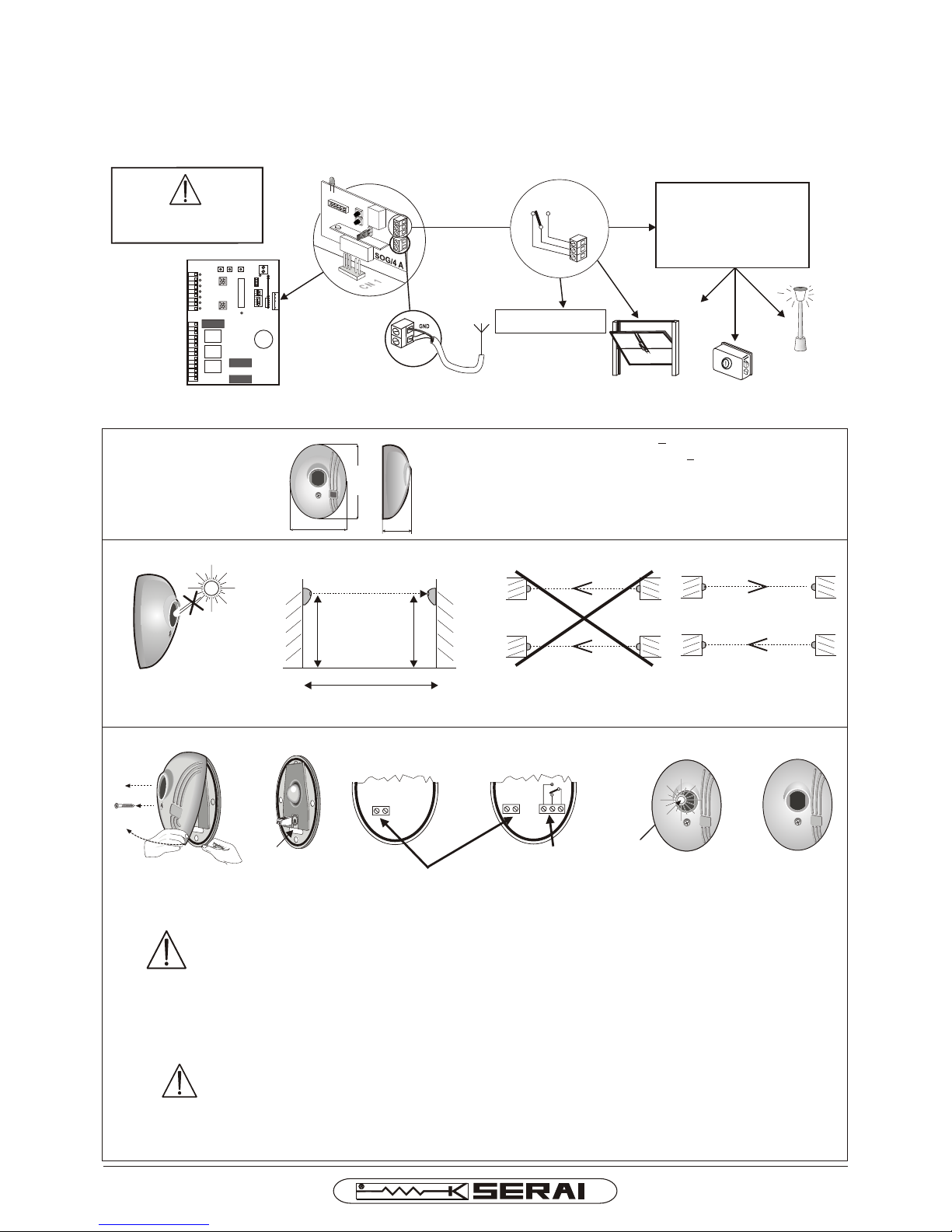
4.3 EXPANDING THE NUMBER OF MINI TRANSMITTERS
If the 32 mini transmitters storable in the built-in receiver are not sufficient, they can be increased by fitting the SOG/4A
receiver (which increases the number of mini transmitters up to 40), possibly with the addition of the SOG/2A expansion
card (which increases the number of mini transmitters up to 794).
After fitting the SOG/4A receiver, all the codes stored in the built-in receiver must be cleared and all the mini
transmitters on the new SOG/4A receiver reprogrammed (see specific instructions). The antenna must be mo-
ved from the terminals on the control unit to the terminals on the SOG/4A
ND
2 CHANNEL
OUTPUT:
AUXILIARY CONTROL
ANTENNA
FIT THE
SOG/4A
RECEIVER
ST
1 CHANNEL
OUTPUT: CONTROL
UNIT START CONTROL PEDESTRIAN CONTROL
ON TERMINALS 2-3
NC
C
NO
Channel 2 output (relay
contact)
Max. applicable voltage =
24Vac/dc
ELECTRIC LOCKS
LIGHTS
OTHER AUTOMATIONS
OTHER
DISCONNECT THE POWER
SUPPLY BEFORE WORKING
ON THE WIRING
Page 14/16
90 mm
70 mm 40 mm
Power supply . . . . . . . . . . . 24 V~ ±10%
Relay output . . . . . . . . . . . . 1A 24 V~
Range . . . . . . . . . . . . . . . . 10 m outdoors - 20 m indoors -
TX absorption . . . . . . . . . . 55 mA a 24 V-; 67 mA a 24 V-;
RX absorption. . . . . . . . . . . 15 mA a 24 V-; 25 mA a 24 V-;
Temperature . . . . . . . . . . . . -10° +60°C
Dimensions and weight . . . 70 x 40 x 90 mm 120 g
5.1 TECHNICAL
SPECIFICATIONS
CHAPTER 5: P/10 PHOTOCELLS
5.2 INSTALLATION POSITION
RECEIVER
NO
TX RX
h MIN
h = 40 cm
MIN
l= 10 m
MAX
l
MAX
RX TX
TX RX
RX RX
TX TX
NO OK
h
MIN
5.3 INSTALLATION
CABLE
ROUTING
HOLE
RECEIVER
TRANSMITTER
RELAY OUTPUT: THE
CONTACT POSITION
REFERS TO WHEN THE
RECEIVER IS ENERGIZED
POWER SUPPLY
+ -
5.2 A The receiver must not be exposed to direct sunlight; recommended height from ground = 50 cm
5.2 C If two pairs of photocells are installed, position the transmitters on opposite sides
NO OK
LED
RECEIVER TRANSMITTER
5.3 A Open the photocell by unscrewing the front screw completely and pulling the tab underneath the appliance
5.3 B Open up the cable routing hole on the base of the housing by either boring it or forcing it
CAUTION
To prevent tiny insects getting inside, the cable routing hole must be exactly the right size
for the cable, and no bigger.
5.3 C Using the drilling template supplied, make the holes required in the fastening surface. Hole sizes:
- Ø 6 mm for wall mounting, in which case use the masonry plugs supplied
- Ø 3.5 mm for mounting on a metal support, in which case use the self-threading screws supplied
Fasten the base of the photocells to the surface
5.3 D Wire up and seal the photocell
CAUTION
always respect the polarity for the receiver power supply connection
5.4 E Check photocell alignment using the red LED on the receiver:
- LED on: photocell not aligned or obstructed
- LED off: photocell aligned
SINCE 1965
NC NO
MERCURIO/524A I E
12
9
1
2
3
4
5
6
7
8
F1F1
F2F2
25
24
START
PED
STOP
FOTO
FCA
FCC
DL8
+
-
ENCODER
PAUSA
LAVORO PROG
F3F3
ONON
SW1
SW2
SOG 4
FOTO-1
+
-
VELOCITA'
REGIME
VELOCITA'
RALLENTAMENTO
13
10
11
14
15
16
17
18
19
20
21
22
23 DL9

CHAPTER 7: GEARMOTOR SPECIFICATIONS
Motor type
Page 15/16
Adjusted via the
power supply voltage
Dimensions and weight
Max gate weight
Power supply
Absorbed current
Absorbed power
Traction and thrust force
Motor power adjustment
Gate speed
Gear ratio
Protection class
Operating temperature
CHAPTER 8
POWER CUT - manual gate release -
8.1 A Fit the release key into the lock on the front panel of the motor
unit and turn it anticlockwise by a half turn.
Push the release flap hard downwards until the release
mechanism is triggered.
The gate can now be moved by hand
CAUTION: The gate must not be resting on the
mechanical end stops, otherwise the force required to
perform the release manoeuvre would break the flap
8.1 B To relock the gate, lift the release flap and remove the key from
the lock cylinder.
Open or close the gate a few cm by hand until the stop pinion
locks, ensuring the limit switch has been pressed.
1/2
216 mm
272 mm
248 mm
82 mm
CHAPTER 6: RZ/24 F FLASHING LIGHT
!
NO
WHEN REPLACING LIGHT BULBS,
ALWAYS USE BULBS WITH
MIN. SPECIFICATIONS:
24V - 25W - E14
2 x 0,75 mm²
POWER SUPPLY
RG58
ANTENNA
CS/07 SR12.07
OPTIONAL CABLE
CONNECTIONS
230 Vac
OK
!
CAUTION:
WE RECOMMEND THAT THE POWER SUPPLY CABLE BE POSITIONED INSIDE A CONDUIT WHICH IS NOT
ACCESSIBLE BY THE USER. IF, ON THE OTHER HAND, THERE ARE ANY ACCESSIBLE PARTS, THESE MUST BE
DOUBLY INSULATED FOR THE USER'S PROTECTION; A CABLE CLAMP MUST ALSO BE USED TO PREVENT THE
SAID CABLE FROM BEING TUGGED OR RIPPED.
RZ/99 SR 10.99
L-SHAPED
HOLDER
In the event of a power cut, the gate can be moved manually by releasing the motor as shown above.
CAUTION: if the gate is in an intermediate position (one of the limit switches has not been pressed) when
power is restored, the next time the open command is sent, the manoeuvre will be performed in
deceleration mode for a maximum time of 300 s. If, during that time, the limit switch is still not reached, the
subsequent closure manoeuvre will be performed normally. To prevent this, the gate must be moved during
the power cut to either the fully open or the fully closed position (so that one of the limit switches is
pressed).
SINCE 1965
MERCURIO/524A I E
irreversible
24 Vdc
IP43
-20 °C ÷ +60 °C
216 X 272 X 248 mm - 9,6Kg
1:28
500 Kg
1,4 A
170 W
400 N
10 m/min

Unsuitable limit switch
setting
Check and adjust the position of the end stop sliding plates
and that they activate the control spring.
CHAPTER 9: TROUBLESHOOTING GUIDE
PROBLEM CAUSE SOLUTION
The gearmotor
is not working
Fuse fault Replace the fuse.
No power
The gate does
not move or
the motor slips
Obstacle impact control
cutting in
Motor force setting
not optimal
Repeat the work times and impact force setting
programming.
The gate does
not complete
its travel
Unsuitable gearmotor
position
Check that the distance between the end stop sliding plate and
the front, outgoing trim of the spring is between 25 and 35 mm.
Unsuitable limit switch
sliding plate
setting
The gate is
jammed against
the mechanical
end stop
Remove the lower casing from the motor.
Unscrew the nuts fastening the base plate bolts.
Remove the motor from its position by releasing the pinion
from the tooth rack.
By hand, move the gate right away from the mechanical
end stop.
Release the motor manually.
Reposition the motor on the base plate.
Set the end stop sliding plates properly.
Replace the lower casing and secure the motor.
If necessary, repeat the work times and impact force setting
programming.
Check the motor power supply input terminals to see if they are
live.
Check that the power supply cable is not cut or broken (cable
replacement must be carried out by an authorised technician).
Check F4 mains fuse efficiency
Check the 24V presence at the motor power supply clamps 5 and 6
Release the gate manually and check that there are no
obstacles. If obstacles are found, remove them.
Repeat the “work times and impact force setting
programming” procedure, setting a greater force.
N.B. The impact control can be switched off by
positioning the SW1 microswitch 1 to ON; in this
case, other safety systems compliant with regulations
in force (e.g. sensitive edges) must be adopted. This
is extremely important as THE INSTALLER IS
LIABLE FOR THE SYSTEM AND FOR ENSURING
ITS OPERATION COMPLIES WITH LEGAL
PROVISIONS.
The remote
control range
is reduced
Unsuitable antenna
connection
Check that the antenna is connected correctly to
terminals 24 and 25.
External antenna
required
To permit maximum reception distance, replace the
internal antenna on the flashing light with an external
one (SERAI OG/50 -SR 25.50).
SOG/4A receiver
in use
Replace the built-in receiver with the SOG/4A card.
The first opening manoeuvre takes place during deceleration (if
the gate is in an intermediate position) and can take up to 300 s;
if it does not occur within this time, the gate must be moved to
the fully open or fully closed position by hand (see chapter 8).
Power cut during
operation
MERCURIO/524A I E 04 16 110321 A4Vf/r - IS MERC524A-E
ELETTRONICA PADOVA
I
SINCE 1965
MADE IN ITALY
VIA ENRICO FERMI, 22
35020 LEGNARO - PADOVA
I T A L I A
PHONE +39 049 79 08 58
FAX +39 049 88 30 529
E-MAIL [email protected]
WEB www.serai.com
TERMS OF GUARANTEE
The company reserves the right to make modifications to the equipment without prior notice thereof. SERAI products are covered by a standard guarantee with a term of 24 months.
Coverage starts on the date on which the tax document constituting proof of purchase is issued and guarantee services shall be provided on the company's premises at Legnaro - PD -
or at the Authorised Service Centres. Carriage costs shall be borne by the Customer.
CE CONFORMITY DECLARATION
SERAI spa declares that the product MERCURIO 524A F has been desifned and manufactured according to the above mentioned directives and standards
WEEE DIRECTIVE 2002/96/EC
This appliance was manufactured after 13/08/2005. To protect the environment: when the equipment is no longer needed, take it to a special WEEE (Waste Electric and
Electronic Equipment) collection centre. Do not dispose of it with normal household waste.
This manual suits for next models
3
Table of contents
Other Serai Gate Opener manuals


