SGM P Series User manual
USER
MANUAL
P-SERIESP-SERIES
P-2P-2
P-2 POIP-2 POI
2
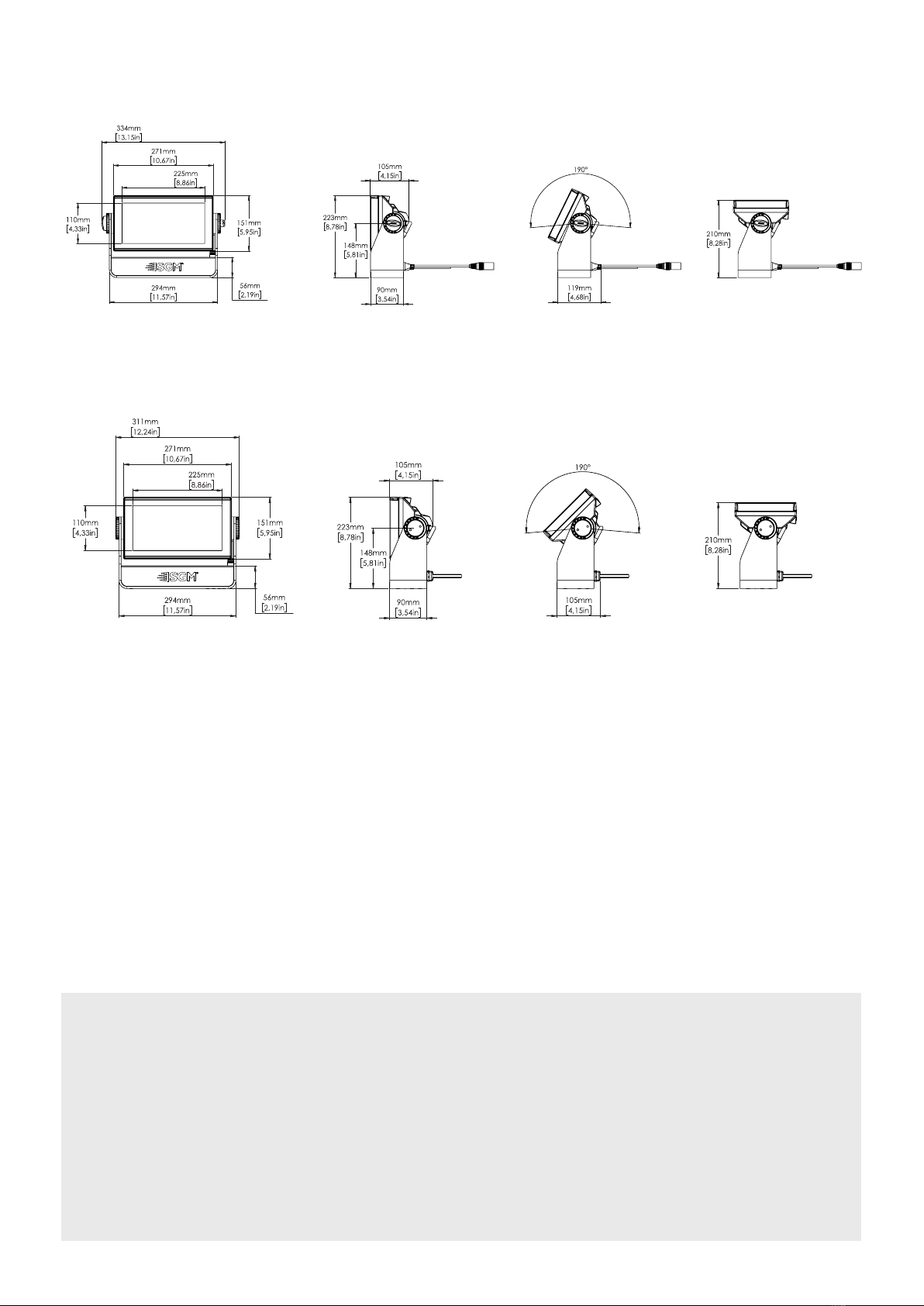
P-2 Dimensions
All dimensions in millimeters and inches. Drawing not to scale.
P-2
USER MANUAL REV. I
© 2021 SGM Light A/S®. The information in this document is subject to change without notice.
SGM and all aliated companies disclaim liability for any injury, damage, direct or indirect loss, consequen-
tial or economic loss, or any other loss occurred by the use of, inability to use, or reliance on the information
contained in this manual. The SGM logo, the SGM name, and all other trademarks in this document pertaining
to SGM services or SGM products are trademarks owned or licensed by SGM, its aliates, and subsidiaries.
This edition applies to rmware version 2.22 or later.
English edition
P-2
P-2 POI
This manual covers installation, use, and maintenance of the SGM P-2.

3
Contents
P-2 Dimensions.............................................................................................................................................................. 2
Safety information......................................................................................................................................................... 4
Before installing this product....................................................................................................................................... 5
Overview.........................................................................................................................................................................6
Parts identication and terminology ........................................................................................................................... 6
Preparing for installation.............................................................................................................................................. 7
Installing/ rigging the P-2 Series.................................................................................................................................. 7
Tilt lock ...........................................................................................................................................................................9
Connecting AC power ................................................................................................................................................... 9
Conguring the device................................................................................................................................................ 10
Display.......................................................................................................................................................................... 10
Connecting to a DMX control device......................................................................................................................... 11
Conguring the device for DMX control ................................................................................................................... 11
About DMX ........................................................................................................................................................................................................... 11
DMX Start address ............................................................................................................................................................................................... 11
Set/ edit DMX address.......................................................................................................................................................................................... 11
Setting the DMX mode.......................................................................................................................................................................................... 11
DMX charts ........................................................................................................................................................................................................... 11
Setting a static color manually................................................................................................................................... 12
Using standalone operation ....................................................................................................................................... 12
Fixture properties........................................................................................................................................................ 12
Factory default .....................................................................................................................................................................................................12
Eects ...................................................................................................................................................................................................................12
Individual xture settings .....................................................................................................................................................................................13
Control menu ............................................................................................................................................................... 13
RDM ..............................................................................................................................................................................15
Supported RDM functions.....................................................................................................................................................................................15
RDM functions ......................................................................................................................................................................................................15
Sensors.................................................................................................................................................................................................................15
Troubleshooting .......................................................................................................................................................... 15
POI Permanent Outdoor Installation.......................................................................................................................... 16
Physical dierences ..............................................................................................................................................................................................16
Conguration ........................................................................................................................................................................................................16
LED Indicator ........................................................................................................................................................................................................16
SGM Addressing Tool ...........................................................................................................................................................................................16
POI Spanner .........................................................................................................................................................................................................17
POI Tilt lock...........................................................................................................................................................................................................17
Installation and rigging the P-2 POI ......................................................................................................................................................................17
Connecting DMX and AC power in POI ................................................................................................................................................................17
P-2 POI connection diagram ................................................................................................................................................................................18
Connecting a wireless transmitter in POI..............................................................................................................................................................18
Accessories ................................................................................................................................................................. 19
Service.......................................................................................................................................................................... 20
Changing P-2 front lens ........................................................................................................................................................................................20
Maintenance................................................................................................................................................................. 21
Fixtures and accessories............................................................................................................................................ 22
Ordering information .............................................................................................................................................................................................22
Support hotline............................................................................................................................................................ 22
Approvals and certications ...................................................................................................................................... 22
User Notes....................................................................................................................................................................23
4
Safety information
• Always power o/ unplug the xture before removing covers or dismantling the product.
• Ensure that the mains power is cut o when wiring the device to the AC mains supply.
• Ensure that the device is electrically connected to earth (ground).
• Do not apply power if the device or mains cable is in any way damaged.
• Do not immerse the xture in water or liquid.
DANGER! Risk of electric shock. Do not open the device.
• Install in a location that prevents accidental contact with the device.
• Install only in a well-ventilated space.
• Install at least 0.3 m (12 in.) away from objects to be illuminated.
• Install only in accordance with applicable building codes.
• Ensure a minimum clearance of 0.1 m (4 in.) around the cooling fans.
• Do not paint, cover, or modify the device, and do not lter or mask the light.
• Keep all ammable materials well away from the device.
• Allow the device to cool for 15 minutes after operation before touching it.
CAUTION: Exterior surface temperature after 5 min. operation = 45° C (113° F). Steady state = 60° C (140° F).
WARNING! Take measures to prevent burns and re.
• Do not look directly at the light source from close range.
• Take precautions when working at height to prevent injury due to falls.
• For Permanent Outdoor Installations (POI), ensure that the xture is securely fastened to a load-bearing surface with suitable
corrosion-resistant hardware.
• For a temporary installation with clamps, ensure that the quarter-turn fasteners are turned fully and secured with a suitable
safety cable. The standard safety wire cable must be approved for a safe working load (SWL) of 10 times the weight of the
xture, made of a grade AISI 316 steel, and it must have a minimum gauge of 3 mm.
• For elevated installations, secure the xture with suitable safety cables, and always comply with relevant load
dimensioning, safety standards, and requirements.
WARNING! Take measures to prevent personal injury.
WARNING!
Read the following safety precautions carefully before unpacking, installing,
powering, or operating the device.
SGM xtures are intended for professional use only. They are not suitable for household use.
Les luminaires SGM sont impropre à l’usage domestique. Uniquement à usage professionnel.
This product must be installed in accordance with the applicable installation code by a person familiar with
the construction and operation of the product and the hazards involved.
Ce produit doit être installé selon le code d’installation pertinent, par une personne qui connaît bien
le produit et son fonctionnement ainsi que les risques inhérent.

5
External cleaning and visual inspection of the xture
Wiring and conduit/ containment
Safety Precautions
Before installing this product
Please visit the SGM ocial website at www.sgmlight.com for the latest version of this user manual/ safety information leaet. Due
to continuous improvements, the instructions may change without notice. SGM always recommends the latest available rmware
version from www.sgmlight.com.
All users of SGM xtures should regularly clean those parts of the xture directly exposed to the elements, such as the
external housing and front lenses. Additionally, all owners of SGM xtures must periodically check the external housing of the
xture for structural breaks, components in bad shape, cracked lenses, or loose screws. To ensure proper operation, but also
to prevent the risk of potential accidents, do not use the xture if the lens, housing, or power cables are damaged. If parts of
the xture appear to be missing, cease use immediately and contact SGM support.
SGM xtures supplied with power and data cable leads are not intended for installation in permanently installed conduit or
containment. When installing xtures in a permanent installation, ensure cable leads are installed as a service loop to an
appropriately rated junction box using suitable cable strain reliefs/ glands. All installed xtures must be securely mounted and
service loop appropriately protected for installation location. All electrical wiring and connections should be completed by a
qualied electrician.
When using electrical equipment, basic safety precautions should always be followed including the following:
1. Do not mount near gas or electric heaters.
2. Permanently installed equipment should be mounted in locations and at heights where it will not readily be subjected
to tampering by unauthorized personnel.
3. The use of accessory equipment not recommended by the manufacturer may cause an unsafe condition.
4. Do not use this equipment for other than intended use.
5. Refer service to qualied personnel or authorized service centers.
6. Do not look directly into the beam for long periods of time, when the xture is on.
7. The xture shall, under no circumstance, be covered with insulating material of any kind.
READ AND FOLLOW ALL SAFETY INSTRUCTIONS.
6
The P-2/ P-2 POI is an IP65/ IP66-rated RGBW LED wash light with a small footprint and high output, designed for multiple applica-
tions, including when wireless operation is essential (POI only).
P-2 Series features:
• A wash light, ood light, and a strobe light, weighing only 6.1 kg/ 13.4 lbs.
• Multi-environmental xture due to its IP65/ IP66 rating that can operate in many environments and in temperatures from
-40° C to 50° C.
• 18 high-power RGBW LEDs divided into three vertical, individually controllable LED segments, for wide ranging color and
eect combinations.
• Fully RGBW color mixing and adjustable color temperature correction (CTC) from 2,000K to 10,000K.
• Native symmetrical lenses of either 15°, 21°, or 43°.
• Dierent beam angles available by using the diusion lters.
• Programmable standalone scenes.
• Fully RDM implemented, compliant with the USITT DMX512 standard.
• Very low power consumption (170 W), and an expected lifetime of the multiple LEDs of 50,000 hours*.
• Optional accessories, such as barndoors, diusion lters, color frames, etc.
• Built-in wireless DMX (POI only).
• Corrosion classied C5-M (marine) for coastal and oshore areas with high salinity (POI only).
* At 70% of luminous output under the manufacturer’s test conditions.
Overview
Illustrations might vary from recieved products.
This is subject to change without notice.
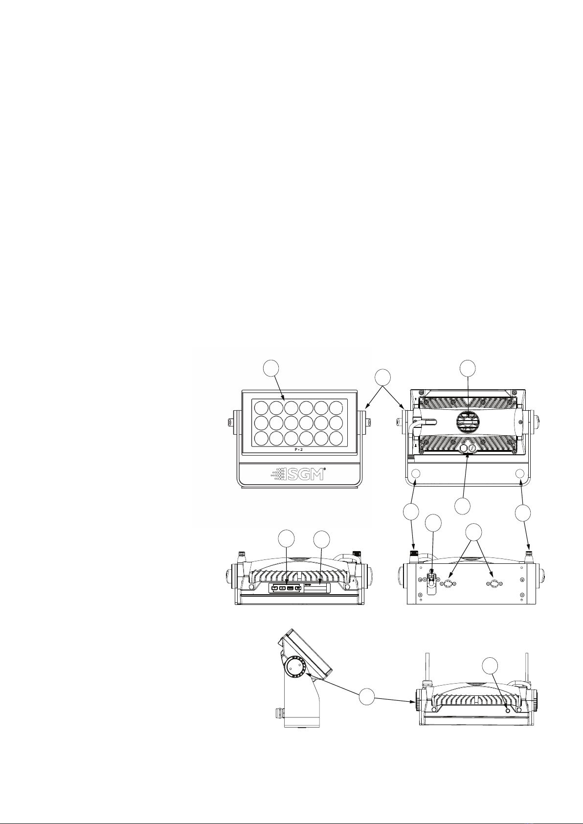
Parts identication and terminology
Figure 1: Parts identication and terminology
P-2 POI
B
A
A: 18 x 10W LEDs
B: P-2 Tilt lock
C: Cooling fan
D: Control panel (POI n/a)
E: OLED Display (POI n/a)
F: DMX in and out
G: Safety wire attachment point
H: Dehumidifiers and GORE-TEX membranes
I: Holes for Omega bracket / M-10 screws (x2)
J: Power cable
K: P-2 POI Tilt lock (POI only)
L: LED indicator (POI only)
C
L
K
J
FH
I
G
DE

7
The P-2 may be installed in any orientation, on the ceiling or on a wall surface.
When installed horizontally with a downward beam-angle, moisture or grime can potentially pool in the fan wells. Under normal op-
eration the moisture will evaporate.
Installing/ rigging the P-2 Series
Unpacking
Unpack the device and inspect it to ensure that it has not been damaged during transport.
The P-2/ P-2 POI is shipped with:
• 1 x Omega bracket with 1/4-turn fasteners (standard only).
• 1 x Mounting bracket with fasteners (standard only).
• 1 x Spanner with magnet (POI only).
• 2 x M-10 screws (POI Only).
• Safety information leaet.
Location/ application
The standard xture is IP65-rated and is designed for both indoor and outdoor events. This means that it is protected from:
• Dust, to the degree that dust cannot enter the xture in sucient quantities as to interfere with its operation.
• Lower pressure water jets from any direction.
The POI xture is IP66-rated and designed for use in outdoor installations. This means that it is protected from:
• Dust, to the degree that dust cannot enter the device in sucient quantities as to interfere with its operation.
• High pressure water jets from any direction.
When selecting a location for the device, ensure that:
• It is situated away from public thoroughfares and protected from contact with people.
• It has adequate ventilation.
• It is not immersed in water.
When using standard xtures outdoors or in wet locations, ensure that:
• The DMX out of the last xture is properly sealed, in accordance with the ingress protection (IP) requirements.
• The DMX out of the last xture is terminated with a 120 ohm resistor between pin 2 and 3 (according to the RS485 standard),
and the DMX out is properly sealed, in accordance with the ingress protection (IP) requirements. Note that a maximum of
32 xtures can be connected to the same DMX link.
Transportation
Always use the supplied packaging or suitable ight case for transportation and storage.
Never carry the xture by connected cables or wires.
Preparing for installation
94mm
3,701in
106mm
4,173in
45mm
1,772in
A
18mm
0,709in
14mm
0,551in
DETAIL A
SCALE 1 : 1
Figure 2: Dimensions for P-2 base locking points
8
Rigging process using SGM Omega brackets
Start the standard rigging process by clearing the working area below, and make sure the work
is performed from a stable platform.
1. Check that the clamp/bracket is undamaged and can bear at least 10 times the weight
of the xture. Check that the structure can bear at least 10 times the weight of all in-
stalled xtures, lamps, cables etc.
2. Bolt the clamp/ bracket securely to the omega bracket with a M12 ½ bolt (min. grade
8.8 C5M) and a lock nut.
3. Align the omega bracket with the P-2 Series base. For standard Omega Bracket, insert
the fasteners into the P-2 Series base bracket, and turn both levers a full 1/4-turn clock-
wise to lock. When using the POI Omega Bracket, insert the included M-10 screws through the bracket holes and tighten
them with a M-10 key until they are fully attached to the base.
4. Working from a stable platform, hang the xture on a truss or other structure. Tighten the clamp/ bracket.
5. Install a safety wire that can bear at least 10 times the weight of the xture. The safety wire attachment point is designed to
t a carabiner AISI316 grade.
6. Verify that there are no combustible materials, cables, or surfaces to be illuminated within 0.3 m (12 in.) of the xture.
7. Check that there is no risk of the head/ yoke colliding with other xtures or structures.
WARNING! Always secure an elevated xture with a safety wire
Fasten a safety wire (not shown) between the load-bearing support structure and the safety wire attachment point on the device.
The safety cable (not included in the package) must:
• Bear at least 10 times the weight of the device (SWL).
• Have a minimum gauge of 3 mm.
• Have a maximum length (free fall) = 30 cm (12 in.).
CAUTION!
• Always use a safety wire of a grade AISI 316 steel.
• Make sure the slack of the safety wire is at a minimum.
• Never use the yoke for secondary attachment.
Figure 4: Installing the P-2
Figure 5: Safety wire attachment point
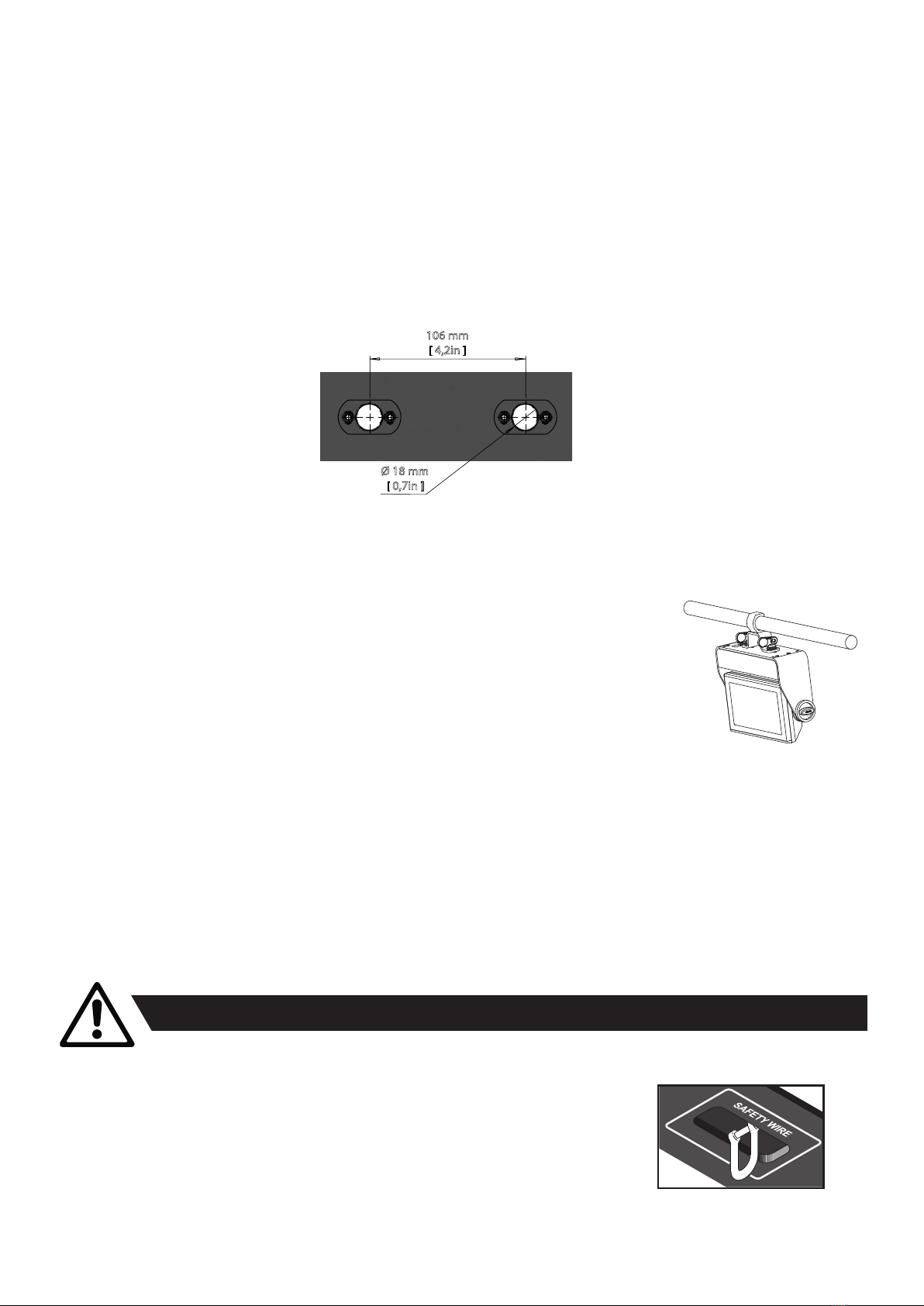
106 mm
[ 4,2in ]
Ø 18 mm
[ 0,7in ]
Figure 3: P-2 Series locking points
In locations with high rainfall, you may wish to fabricate a rain shield above the xture, or modify the position and orientation of the
xture to minimize pooling.
All SGM xtures have locking points at the base for installation and rigging. In both standard and POI xtures, the distance between
the points from center to center is always 106 mm. However, while the base of the P-2 standard xture includes 1/4 turn fastener
camlocks to mount the omega brackets, the POI products come with M-10 nuts for M-10 screws.
Always use the supplied omega bracket to rig a standard P-2. Lock the bracket with the 1/4-turn fasteners.
N.B.: The 1/4-turn fasteners are only locked when turned fully clockwise.
Depending on the structure, please use appropriate and secure methods for mounting the Omega brackets.
PLEASE NOTE
The supplied omega bracket is not rated for POI (Permanent Outdoor Installation C5-M rated material). See more about
“Installation and rigging the P-2 POI” on page 17.
9
The P-2 Series can operate on any 100–277 V, 50/ 60 Hz AC mains power supply, and draws approximately 1,2 A at full power (230 V).
Connect the xture to AC power by installing a power connector to the bare ended mains cable. The xture must be grounded/
earthed and able to be isolated from AC power. The AC power supply must incorporate a fuse or circuit breaker for fault protection.
The power cable color coding is given in gure 8:
• Connect the black wire to live.
• Connect the white wire to neutral.
• Connect the green/ yellow wire to ground (earth).
For a temporary outdoor installation, the mains cable must be tted
with a grounded connector intended for exterior use.
For permanent installations, have a qualied electrician to wire the mains cable directly to a suitable branch circuit. The junction’s
ingress protection (IP) rating must be suitable for the location. Always use a junction box with a proper IP class suitable for the
environment.
NOTE: In POI versions, the power is wired as in the standard versions by installing a power connector to the bare-ended
mains cable. For connecting AC power in POI xtures, please refer to “Connecting DMX and AC power in POI” on page 17.
After connecting the P-2 to power, run the on-board test by selecting the option “TEST→ SELFTEST” in the menu, to ensure that the
xture and each LED are functioning correctly. POI versions have to be tested through RDM.
CAUTION!
Do not open the xture to replace the supplied power cable.
Do not connect the xture to an electrical dimmer system, as doing so may cause damage.
Connecting AC power
The fixture must be grounded/
earthed and be able to be isolated
from AC power. The AC power
supply must incorporate a fuse or
curcuit breaker for fault protection.
Color
Black
White
green/yellow
Conductor
live
neutral
ground (earth)
Symbol
or
L
N
Wire
Figure 8: Connecting AC Power
The xture can be tilted from 0° - 180°.
In P-2 standard versions, there is no need for special tools to adjust the tilt angle.
Take the following steps for adjusting the tilt in standard P-2:
1. Loosen the two tilt knobs (one on each side) by turning them counter-clockwise.
2. Tilt the xture to the desired angle and hold it.
3. Lock the position by re-tightening both tilt lock knobs clockwise.
If there is resistance when tilting the xture, the knobs may need to be loosened further.
CAUTION!!
If the xture has been operating, always allow it to cool down for 15 minutes before handling.
NOTE: In POI versions, SGM provides a POI Spanner with a pig-nose key for tilt adjustment. Either use the large or the small
pig-nose key, depending on the type of xture. See “POI Tilt lock” on page 17 to know more about the tilt lock in P-2 POI.
Figure 7: P-2 Standard tilt lock
Tilt lock
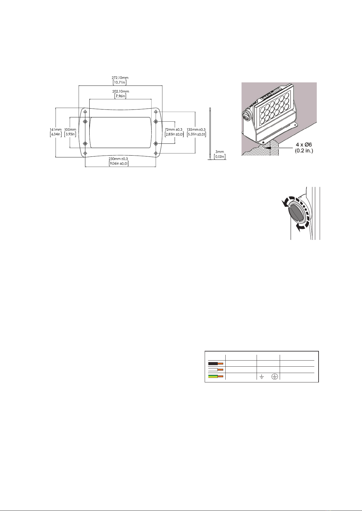
P-2 Mounting bracket
The standard P-2 includes a mounting bracket with fasteners that can be attached to the xture. The four rubber push-in bumpers
prevent the xture from sliding while operating and protect delicate surfaces from scratching.
Please note this item is not intended for permanent outdoor installation.
When installing the xture indoors on the ground or on a wall, remove the four rubber push-in bumpers from the mounting bracket.
Then securely fasten the xture to the ground/ wall by using 4 x 6 mm (1/4 in.) fasteners.
Figure 6: P-2 mounting bracket
10
Operational mode (A)
Displays the current mode (quick color, standalone, or DMX mode). The xture
is set by default to be controlled in DMX mode.
DMX Address (B)
Displays the current DMX address. The DMX address is altered directly from
this view.
External data indicator (C)
The DMX signal indicator will ash when the DMX signal is received.
External data protocol (D)
Shows the external data protocol (CRMX™ or DMX).
• When ‘DMX’ is displayed: the xture responds to data received through cabled DMX.
• When ‘CRMX’ is displayed: the xture responds to data received through wireless DMX.
The next available DMX address will show immediately, depending on the xture’s DMX footprint.
Error Indicator
If any errors are detected, the message ‘ERR’ will ash in the display for easy detection.
To read the error message, select ENTER → INFO → ERRORS in the menu.
Conguring the device
The P-2 Series can be set up by using the control panel and OLED multi-line display on xture’s head or through RDM.
Please note: In POI versions, there is no display mounted in the xture. The adjustments are made through RDM.
For more information see “RDM” on page 15.
The OLED display is the user interface of the xture and displays the current status and menu of the xture. The display panel
can be used to congure individual xture settings, check the xture’s wireless status, conrm the rmware version, and read error
messages. The complete list of the menu and all commands available are listed in “Control menu” on page 13.
Before turning on the P-2, make sure the power cable is properly connected. When the xture is powered on, it boots and resets
before displaying the selected operating mode and DMX start address. Navigate through the menus and options using the arrow
buttons, and select items using the ENTER button.
Using the display panel
• Press the ‘ENTER’ button to access the menu or make a selection.
• Press the arrow buttons to scroll up and down in the menus.
• Press the ‘ESC’ button to take a step back in the menu.
Shortcuts
• ESC + ENTER: Press ENTER to conrm factory defaults.
• ESC + UP: Press ENTER to start LED test.
• UP + DOWN arrows simultaneously = ip the display upside-down.
Figure 9: OLED display and control panel
Display
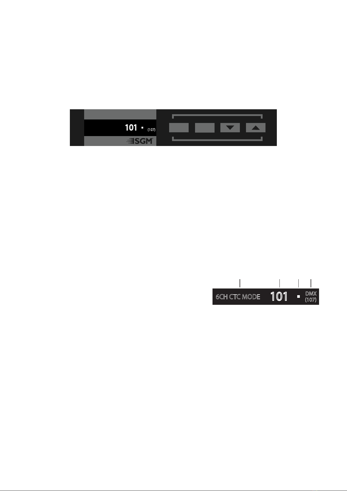
Figure 10: P-2 Display
Lorem ipsum dolor sit
6CH CTC MODE
101
(107)
DMX ESC ENTER
6CH CTC MODE
101 (107)
DMX
A B C D
A - Operational mode
B - DMX address
C - External data indicator (DMX)
D - External data protocol + next
available DMX address

11
The P-2 Series is controllable using a DMX control device. It can be connected using either a DMX cable, or via the xture’s built-in
CRMX wireless receiver system (POI only).
When using a cabled DMX system, connect the DMX-In cable (with male 5-pin XLR plug) to the input connector and DMX-Out
cable (with female 5-pin XLR plug) to the output, both located on the rear of the xture’s base. For outdoor installations, use only
IP-rated XLR connectors suitable for outdoor use. Terminate the DMX-Out cable of the last xture in the data link with a 120 ohm
DMX termination.
Note that SGM xtures provide a passive DMX Thru signal as DMX Out instead of an active output signal.
NOTE!
For POI versions, please refer to “Connecting DMX and AC power in POI” on page 17 to see how to connect DMX and AC power.
Connecting to a DMX control device
About DMX
The P-2 Series can be controlled using signals sent by a DMX controller on a number of DMX channels.
DMX is the USITT DMX512-A standard based on the RS-485 standard. The signal is sent as DMX data from a console (or a control-
ler) to the xtures via a shielded twisted pair cable designed for RS-485 devices.
The cables can be daisy chained between the xtures, and up to 32 xtures can be connected to the same DMX link. Up to 300 me-
ters (1000ft.) of cable is achievable with high quality DMX cables. All DMX links must be terminated by connecting a DMX termination
plug to the last xture´s 5 pin DMX-Out connector.
PLEASE NOTE:
• Standard microphone cable is not suitable for transmitting DMX.
• Up to 32 xtures can be linked to the same DMX chain. Additional xtures will overload the link.
DMX Start address
The P-2 Series can be operated in dierent DMX modes. For any of the modes, the rst channel used to receive data from a DMX control
device is known as the DMX start address.
For independent control, each P-2 must be assigned its own DMX start address. For example, if the rst P-2 is set to 6ch CTC DMX
mode with a start DMX address of 101, the following P-2 in the DMX chain should then be set to a DMX address of 107. As the rst xture
uses all the rst 6 DMX channels, including channel 101, the next available channel is 107 (101+6=107 >> 107).
If two or more P-2s have the same DMX start address, they will behave identically. Incorrect settings will result in unpredictable
responses from the lighting controller. Address sharing can be useful for diagnostic purposes and symmetrical control.
Set/ edit DMX address
The DMX address is shown on the OLED display in the control panel. To change
the address setting, press the up and down arrows. When the desired address
is displayed, press ENTER to save the setting. For your convenience, the next
available DMX address is displayed to the right. Note that channel spacing is
determined by the number of channels of the DMX mode.
See “Conguring the device” on page 10 for instructions on using the display
panel.
The P-2 Series also oers the option to set the DMX address through RDM.
NOTE: POI versions are only addressable via RDM. See “POI Permanent Outdoor Installation” on page 16.
Setting the DMX mode
Select ENTER → MODE → SELECT MODE in the control panel. It is possible to chose the DMX mode that provides the xture the
controls that you require. Conrm the chosen mode by pressing ‘Enter’.
DMX charts
The P-2 Series operates in dierent DMX modes. Each DMX mode has its own DMX chart. All DMX charts are available for download
at www.sgmlight.com under the respective product or upon request via [email protected].
Conguring the device for DMX control
Figure 11: Set/edit DMX address
6CH CTC MODE
101
(107)
DMX
DMX address
Next
available
DMX address

12
Standalone operation can be used when the xture is not connected to a control device. It can be pre-programmed with a series of
up to 24 scenes, playing continuously in a loop. Up to three standalone programs can be dened and run from the menu, and one of
the programs can be set to run by default whenever the xture is powered on.
Each of the three available standalone programs contains 24 user-denable scenes with its own RGB and shutter settings.
Each scene has a denable fade-in time for the transition from one color to the next, and a wait (static) time of up to 120 minutes and
59 seconds.
To record a stand-alone program, press ENTER → MANUAL → EDITOR.
The standalone mode of the xture’s startup is enabled by selecting:
ENTER → SETTINGS → STARTUP MODE → SELECT STARTUP MODE →
STANDALONE.
To select the xture’s startup program, press:
ENTER → SETTINGS → STARTUP MODE → STARTUP PROGRAM.
The chosen program will run its length cyclically whenever the xture is powered on.
To run an internal program, go to: ENTER → MANUAL → RUN PROGRAM.
To stop an active internal program, go to: ENTER → MANUAL → STOP PROGRAM.
See “Control menu” on page 13 for detailed information about the manual menu.
Please note: In POI versions, conguring the xtures can only be done through RDM.
Using standalone operation
Figure 12: Standalone operation
Setting a static color manually
Factory default
When restoring the P-2 Series to the factory defaults, the following will be set:
• Set DMX address to 1
• Set 6 Channel CTC DMX mode
• Set screensaver to OFF
• Disable Startup Programs
Eects
Colors and LED Panels
The P-2 Series features 18 high-power RGBW 10W LEDs divided into three in-
dividually controllable segments, which generate wide-ranging color eects and
pixel-mapping combinations for creative lighting designs.
The xture can operate in RGB calibrated mode which ensures that colors are
compatible across the range of SGM xtures.
However, the P-2 Series also oers the ability to operate in RAW mode with full
control of each color.
Color temperature correction
The P-2 Series oers seamless CTC (color temperature correction) control from
2,000° Kelvin - 10,000° Kelvin.
Ultra high-speed strobe eect
The ultra high-speed strobe eect generates random strobe and pulse eects with variable speed.
Fixture properties
Figure 13: P-2 Pixel segments
PANEL 1 PANEL 2 PANEL 3
The P-2 can be congured to display a predened and static color.
To set up a static color select ENTER → MANUAL → QUICK COLOR.
Note that, once the MANUAL → QUICK COLOR settings are changed, the xture is set, by default, to automatically start in quick color
mode whenever it is powered on. This can be reset through the menu SETTINGS → STARTUP MODE → SELECT STARTUP MODE.
The current quick color program can always be stopped by going to:
ENTER → MANUAL → STOP PROGRAM.
See “Control menu” on page 14 for detailed information about the manual menu.
Please note: In POI versions, conguration of the xtures can only be done through RDM.
• Set all Quick Color values to zero
• Set all values in Manual Programs to zero
• Set Fan mode to Standard
• Set Frequency to Default

13
Control menu
Level 1 Level 2 Level 3 Level 4 Function
MODE Select mode - - Select DMX mode.
MANUAL QUICK COLOR RED 0-255 Static quick color - red mix (0-255). Sets xture to quick
color startup mode.
GREEN 0-255 Static quick color - green mix (0-255). Sets xture to quick
color startup mode.
BLUE 0-255 Static quick color - blue mix (0-255). Sets xture to quick
color startup mode.
WHITE 0-255 Static quick color - white mix (0-255). Sets xture to quick
color startup mode.
FULL COLOR CALIB. On or o Select between color calibrated or RAW color mode.
RUN PROGRAM 1, 2 or 3 -Runs internal sequence 1, 2 or 3.
STOP PROGRAM - - Stops current running internal sequence or Quick Color.
EDITOR Program - Edits scenes.
INFO PRODUCT TYPE - - Displays product type.
FIRMWARE VERSION - - Displays installed rmware version.
SERIAL NUMBER - - Displays xture’s serial number.
RDM ID - - Displays xture’s RDM ID. (Unique RDM ID for identication).
DMX VIEW Up to 492 DMX addresses -Display received DMX channels.
SENSORS Mainboard - Displays xture temperatures.
LED Left -
LED Center -
LED Right -
Humidity -Displays humidity percentage.
AC Connected - Displays whether power is connected or not.
Battery PCT -Displays battery level.
Charging - Displays whether the battery is charging or not.
Battery VDC -Displays battery voltage.
Wireless Signal -Displays wireless signal strength.
Beam angle
The P-2 can be equipped with 43°, 21°, and 15° lenses.
Individual xture settings
Setting the dimming curve
The setting of the dimming curve will determine the xture’s behaviour, when changing the light intensity between 0% - 100%.
Linear control provides uniform adjustment throughout dimming curve. Gamma corrected dimming provides ner control at low light
levels, where the eye is more sensitive to change. By default, the P-2 uses gamma corrected dimming. For a uniform response, set
all xtures to the same dimming curve.
Flipping the OLED display (POI n.a.)
If the xture is installed hanging upside down, it may be useful to ip the display so that it is easier to read.
To ip the display, press ENTER and select SETTINGS → FLIP DISPLAY, or press the up and down buttons on the control panel at
the same time.
Setting the OLED display saver (POI n.a.)
By default the OLED display dims down after a short period when the control panel is not in use. The display can also be set to turn o
completely, ideal when a pitch-black environment is required. Pressing any key will always turn on the display or restore it to normal
brightness.
To congure the display settings, press ENTER → SETTINGS → DISPLAY SAVER.
NOTE: To avoid the risk of display deterioration caused by long term usage, it is recommended to select the setting → DISPLAY OFF.
Setting the fan mode
For operating environments where low-noise is a requirement, or where the xture will be operating in high temperatures, it is possible
to adjust the default fan speed by going to SETTINGS → FAN MODE in the menu.
NOTE: In POI version, the fan mode adjustment is possible through RDM.

14
Level 1 Level 2 Level 3 Level 4 Function
INFO SENSORS Wireless Paired -Displays wireless connection status.
On Time Red 1 - Display LED total power on time. (R, G, B, W).
On Time Green 1 -
On Time Blue 1 - Display LED total power on time. (R, G, B, W).
On Time White 1 -
On Time Red 2 -
On Time Green 2 -
On Time Blue 2 -
On Time White 2 -
On Time Red 3 -
On Time Green 3 -
On Time Blue 3 -
On Time White 3 -
POWER ON TIME - - Displays xture total power on time.
LED ON TIME - - Displays LED total power on time. (R, G, B, W).
ERRORS - - Displays error codes.
SETTINGS WIRELESS DMX LOG OFF - Sends Log o command to the CRMX System.
ENABLE/ DISABLE - Enable/ disable wireless DMX functionality.
BRIDGE - Displays strength of the wireless connection.
STATUS - Displays wireless connection status.
STARTUP MODE SELECT STARTUP MODE -
STARTUP PROGRAM Select
startup
program
Default operating mode when xture is powered on:
1. DMX (factory default).
2. Standalone.
3. Quick Color.
LED FREQUENCY SET LED FREQUENCY -Sets LED frequency.
FLIP DISPLAY - - Flips control panel display.
DISPLAY OFF - - Toggles automatic display sleep.
FAN MODE STARDARD - Controls fan’s speed.
SILENT -
MAX POWER -
FACTORY DEFAULT - - Resets the xture to factory default settings.
SERVICE PIN - - -
SERVICE MENU - - -
TEST SELF TEST Start/ stop self-test - Activates automated self-test.
DISPLAY TEST - - Test the xture display.
COLOR TEST Start/ stop color test -Test the LED segments of the xture.
NOTE: This menu structure applies to all products delivered from February 2018, running rmware 2.22.

15
Problem Potential cause(s) Remedies
Fixture does not respond or appears to
be o.
No power to the xture. Conrm that the power is switched on; conrm that the cables are
plugged in.
Fixture suddenly turned o. Power was turned o. Check the power supply, switches and breakers.
Fixture suddenly stopped responding. The DMX console was disconnected/ tampered with. Inspect the DMX console and connections.
DMX cables were disconnected. Inspect DMX cables.
Fixture operates irregularly/ abnormally. DMX address or DMX mode is incorrect. Inspect and enter the correct DMX address or mode.
DMX cable polarization is inverted (pin 2 + 3). Install a phase-inverter to reverse the polarity, or replace cables.
DMX link is not terminated. Install a XLR 120 ohm DMX termination at the end of the DMX link.
Corrupted DMX cable. Replace or repair defective cables and/ or connectors.
The xture operates an internal program. Enter in the menu and go to → MANUAL → STOP PROGRAM.
A corrupted xture generates noise/ disruptions on
the DMX link.
Track and isolate the corrupted xture.
Color is uneven in low output The minimum values is out of calibration. Contact your local SGM dealer or [email protected].
Troubleshooting
Supported RDM functions
The P-2 Series features support for various RDM functions.
RDM (Remote Device Management) is a protocol enhancement to USITT DMX512 that allows bi-directional communication between
the xtures and the controller over a standard DMX line. This protocol will allow conguration, status monitoring, and management.
A RDM controller is needed to control the supported parameters. See the tables below for supported RDM functions.
RDM functions
RDM
Name Sensor Type
Mainboard Temperature
LED Left Temperature
LED Center Temperature
LED Right Temperature
Humidity Other
LED on Time Hours Red 1 Time
LED on Time Hours Green 1 Time
LED on Time Hours Blue 1 Time
LED on Time Hours White 1 Time
Name Sensor Type
LED on Time Hours Red 2 Time
LED on Time Hours Green 2 Time
LED on Time Hours Blue 2 Time
LED on Time Hours White 2 Time
LED on Time Hours Red 3 Time
LED on Time Hours Green 3 Time
LED on Time Hours Blue 3 Time
LED on Time Hours White 3 Time
PID Actions allowed Name
0x0082 Device label
0x0081 Manufacturer Label
0x00E0 DMX Personality
0x00E1 DMX Personality Description
0x0200 Sensor Denition
0x0201 Sensor Value
0x0080 GET Device Model Description
0x0400 GET/ SET Device Hours
0x0051 GET Parameter Description
0x0500 / 501 Display Invert / Level (POI n.a.)
PID Actions allowed Name
0x0090 Factory Defaults
0x1001 Reset Device
0x0120 Slot Info
0x0121 Slot Description
0x0122 Default Slot Value
0x8626 SET CRMX Log O
0x8060 GET Serial number
0x8625 GET/ SET FAN 0=AUTO 1=LOW
2=HIGH 3=FULL
0x8620 GET/ SET Led freq (197647Hz)/ value
Please note: The RDM controller communicates with the xtures to show only the available options for each RDM function. The table is subject to change without notice.
Sensors
RDM enables various sensor readouts for remote device monitoring. See the table below for sensors and sensor types.
Please note: The RDM controller communicates with the xtures to show only the available sensors for this xture. The table is subject to change without notice.

16
Figure 15: SGM Addressing tool
The SGM POI versions are designed for permanent outdoor installation and are IP66-rated. POI versions are designed for use in
maritime and oshore environments, as per the CX/C5-M corrosion-resistance class.
Physical dierences
The POI version diers from the standard version by having xed-chassis power and DMX cables, and heavy-duty cable glands. The
display and control panel have been removed.
Conguration
The P-2 POI does not include a display, therefore it has to be congured through RDM (Remote Device Management). See “RDM”
on page 15 for more information.
In P-2 POI, the DMX address and DMX mode can only be set through RDM. When addressing through USB powered DMX/ RDM
devices, ensure DMX link is terminated, and keep a short cable length as much as possible.
Regarding the DMX modes for POI, they are the same as the P-2 standard. Visit www.sgmlight.com to see all DMX charts available
under the respective product, or upon request via [email protected].
PLEASE NOTE!
Remote Device Management (RDM) requires fully compliant DMX cable to be installed and terminated.
When setting addresses through RDM and using USB dongles, disable the USB selective suspend to ensure a proper
voltage on the DMX link. If any lag or trouble occurs when addressing, decrease the cable length range to <12 m. and only
address one xture at a time.
LED Indicator
The LED indicator is located on the xture’s head (same place where the display is located in
standard P-2), and shows the current status of the xture.
The LED indicator has three dierent colors and three possible stages: static, ashing, or o.
• Solid Orange: xture is starting up.
• Blinking Green: wireless and/ or wired DMX connected.
• Solid Green: no wireless or wired DMX connection.
• Blinking Red: wireless and/ or wired DMX connected but Error(s) occurred.
• Solid Red: no wireless or wired DMX connection but Error(s) occurred.
• O: xture is o or indicator LED is set to auto dimming (set via RDM).
SGM Addressing Tool
SGM provides a Windows software tool designed to allow the user to address and congure the xtures through RDM. Changing the
settings is done in the exact same way as it is in the display.
This tool is available for download at www.sgmlight.com, and has to be used with the SGM USB 5-Pin-XLR Uploader cable POI if
the luminaire does not use XLR connectors in the DMX cable, or the SGM USB uploader cable if the luminaire uses XLR 5-pin DMX
connectors (available from your SGM dealer).
POI Permanent Outdoor Installation
P-2 POI
B
A
A: 18 x 10W LEDs
B: P-2 Tilt lock
C: Cooling fan
D: Control panel (POI n/a)
E: OLED Display (POI n/a)
F: DMX in and out
G: Safety wire attachment point
H: Dehumidifiers and GORE-TEX membranes
I: Holes for Omega bracket / M-10 screws (x2)
J: Power cable
K: P-2 POI Tilt lock (POI only)
L: LED indicator (POI only)
C
L
K
J
FH
I
G
DE
Figure 14: P-2 POI LED indicator
17
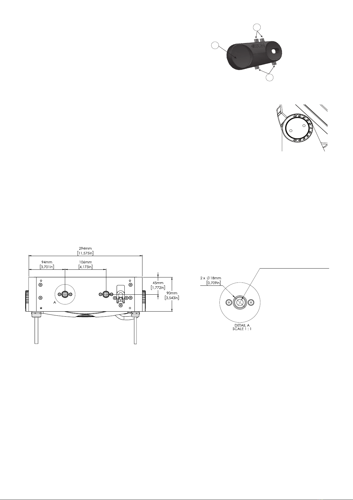
POI Spanner
The P-2 POI includes a spanner with a magnet, this is for establishing connec-
tion between the xture and the wireless transmitter.
The spanner also has two types of pig-nose keys used for tilt adjustment in
POI xtures. Depending on the type of xture, either use the large or the small
pig-nose keys.
In P-2 POI devices the largest pig-nose key is used for tilt adjustment.
POI Tilt lock
The tilt angle in POI xtures may be adjusted by using the large pig-nose key provided in the spanner.
To adjust the tilt angle in P-2 POI, take the following steps:
1. Make sure the xture has cooled down before handling.
2. Take the spanner and turn both tilt lock knobs (one on each side) counter-clockwise by using
the large pig-nose key. Knobs are loosened by turning counter-clockwise.
3. Tilt the xture to the desired angle and hold it.
4. Lock the position by tightening the tilt lock knobs clockwise with the same pig-nose key.
Installation and rigging the P-2 POI
While the base of the standard products includes 1/4-turn fastener camlocks for omega brackets, the base of POI products comes
with M-10 nuts for M-10 screws. The M-10 screws are included in the package in the same amount as the number of M-10 nuts at
the base.
The P-2 POI has two M-10 nuts at the base that can be used for installation and rigging. The SGM Omega bracket (not included) or
a customized bracket is needed to install the xture. Review the dimensions below for integration with brackets or supports.
The SGM POI Omega bracket suited for M-10 holes can be ordered as an accessory. Contact your local SGM dealer for further
information on correct POI-rated mounting.
B
C
AA: Magnet
B: Small pig-nose key
C: Large pig-nose key
Figure 16: POI Spanner
Max. insertion depth 12mm [0,472in]
Figure 18: P-2 POI base with dimensions
Figure 17: P-2 POI Tilt lock
Connecting DMX and AC power in POI
DMX in and DMX out are in the same cable. See more in gure 19 about the SGM POI DMX cable.
The power is wired as in the standard version. See “Connecting AC power” on page 9.
For permanent installations, have a qualied electrician to wire the mains cable directly to a suitable branch circuit. The junction’s
ingress protection (IP) rating must be suitable for the location.
For a temporary installation, the mains cable may be tted with a grounded connector intended for exterior use.
PLEASE NOTE!
• Standard microphone cable is not suitable for transmitting DMX.
• Up to 32 xtures can be on the same DMX link. Additional xtures will overload the link.
• The last xture must always be tted with a 120 ohm resistor between +5V and -5V cables to the xture’s DMX out.
• SGM xtures provide a passive DMX Thru signal as DMX Out instead of an active output signal.

18
P-2 POI connection diagram
Connecting a wireless transmitter in POI
In POI versions with wireless, it is necessary to pair the xture with a new transmitter (by default, the xture is linked to the SGM
factory transmitter).
In order to do so, make sure the xture is powered on before taking the following steps:
1. Using the spanner that comes with the xture, place the magnet close to the LED indicator and wait for 3 seconds. The LED
indicator will blink orange for 1-2 seconds before switching to static green again. The xture can now be paired with a new
transmitter.
2. Go to the wireless transmitter and press “connect” or “link”. Now the external third-party transmitter and the internal SGM
receiver should be linked together.
Repeat the process to link the xture to another transmitter.
Disconnecting a wireless transmitter in POI
To disconnect the P-2 POI from the currently paired wireless transmitter, simply hold the magnet for 3 seconds over the LED indicator.
The LED indicator blinks orange for 1-2 seconds, switching back to green again. The xture is now logged o.
Max. 32 units/DMX line
DMX 512 / Cat5e
Compatible Cable
1 2
XX
SGM
SGM SG
Shield
Wire Color
White
Red
Conductor
Black
Yellow
Ground
DMX IN: Data -
DMX IN: Data +
DMX OUT: Data -
DMX OUT: Data +
SGM POI DMX Cable
Shield / GND
Standard Junction Box
(by Others)
Black / Live
White / Nuetral
Green & Yellow / Ground
Shield / Ground
White / DMX in / Data -
Red / DMX in / Data +
Yellow / DMX Out / Data +
Black / DMX out / Data -
Voltage Barrier
Power
Shield / GND
End Junction Box
(by Others)
Black / Live
White / Nuetral
Green & Yellow / Ground
Shield / Ground
White / DMX in / Data -
Red / DMX in / Data +
Yellow / DMX Out / Data +
Black / DMX out / Data -
Voltage Barrier
120 Ohm Resistor
installed between
Data + & -
DMX Data -
DMX Data +
DMX 512 / Cat5e
Compatible Cable
in Conduit (by others)
To Luminaire To Luminaire
Power Cable
in Conduit
(by others)
Power Cable
in Conduit
(by others)
Data Cable
in Conduit
(by others)
DMX Data -
DMX Data +
Data Cable
in Conduit
(by others)
Splice Link / Connection
Fixture Power Lead Fixture Data Lead
Fixture Data Lead
Fixture Power Lead
Fixture Power Lead Fixture Data Lead
DMX 512 / Cat5e
Compatible Cable
in Conduit (by others)
Junction Box
Power Power
Figure 19: Connecting DMX and AC Power in P-2 POI
19
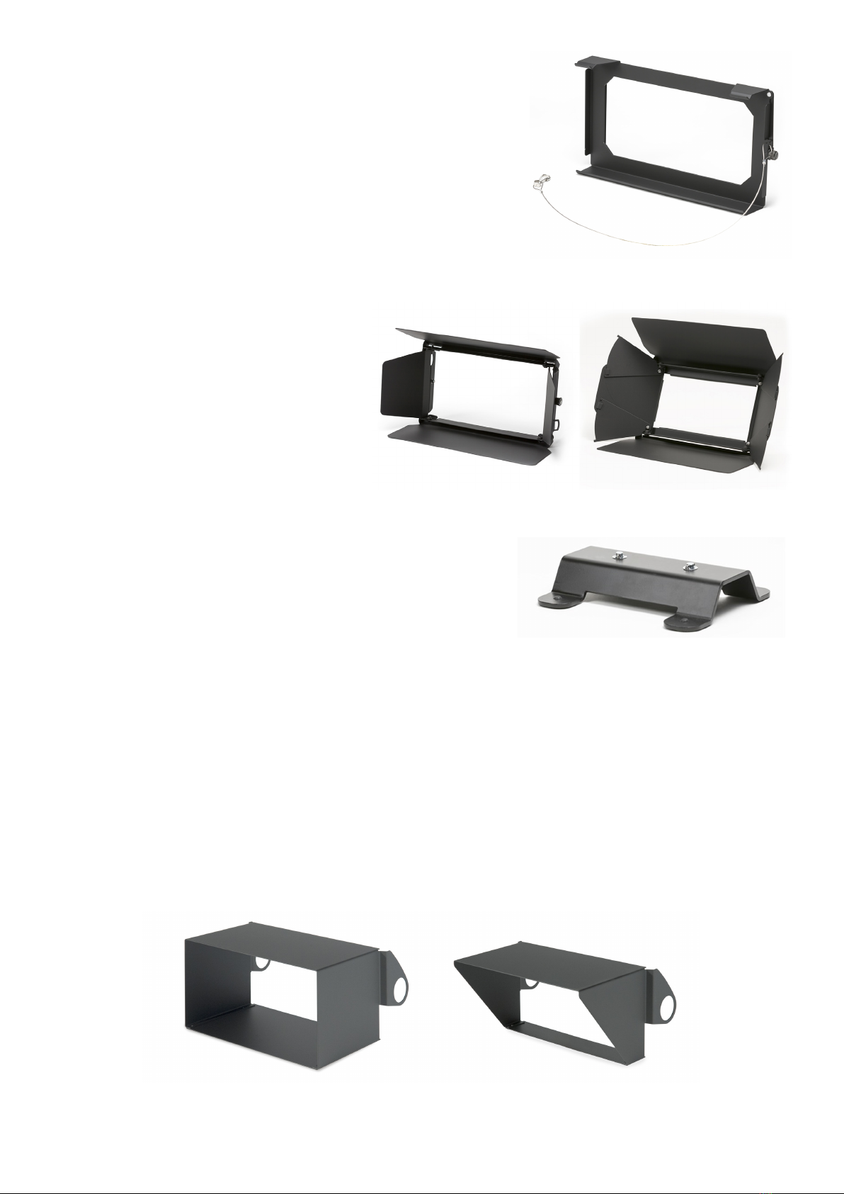
Accessories
The P-2 Series can be used with various accessories such as barndoors, color frame,
and anti-glare shields.
To get to know all the available P-2 Series accessories, go to www.sgmlight.com, or
contact your local SGM dealer.
Accessory holder
The Accessory holder is a mandatory base for holding Barndoors and Color frames
for the P-2 Series xture. It is a clip-on accessory that includes a safety wire that
needs to be attached to the bracket of the xture, and a knob on the side to allow the
sliding of barndoors, color frames or rigid diusion lters.
Barndoors
The P-2 Series has 4-way and 8-way barndoors. The
dierence between the two types is that the 8-way
barndoors give an extra control when cutting the light,
by extending and adjusting the width of the side aps.
The barndoors are designed and intended to be
mounted on the xture without the use of any tools. It
is only required the use of the accessory holder where
the barndoors will slide and t in.
The P-2 Series barndoors are also compatible with the
use of color frame and diusion lters.
Floorstand
The P-2 Series has an optional oorstand, ideal when there is a frequent need of
changing the position of the xture from hanging to standing.
The P-2 oorstand is easy to mount or remove by simply using the 1/4-turn fas-
teners.
PLEASE NOTE!
The accessory holder, the barndoors and the oorstand are not intended for perma-nent
outdoor installations.
Anti-glare shields
The P-2 Series features two dierent types of optional anti-glare shields:
• Full anti-glare shield - covers the full xture’s opening.
• Half anti-glare shield - covers half of the xture’s opening.
Using the anti-glare shields will remove any unwanted glare and reections.
The anti-glare shields are easily mounted by removing the two tilt lock bolts, one on each side of the xture. Ret the anti-glare shield
in position and screw the tilt-lock bolts again.
Note: This accessory is suitable for both permanent outdoor and indoor installations.
Figure 21: P-2 Series Barndoors
Figure 23: P-2 Series Anti-glare shields
Figure 22: P-2 Series Floorstand
Figure 20: P-2 Series Accessory holder
For further information and other possibilities see www.sgmlight.com or contact your local SGM dealer.
20
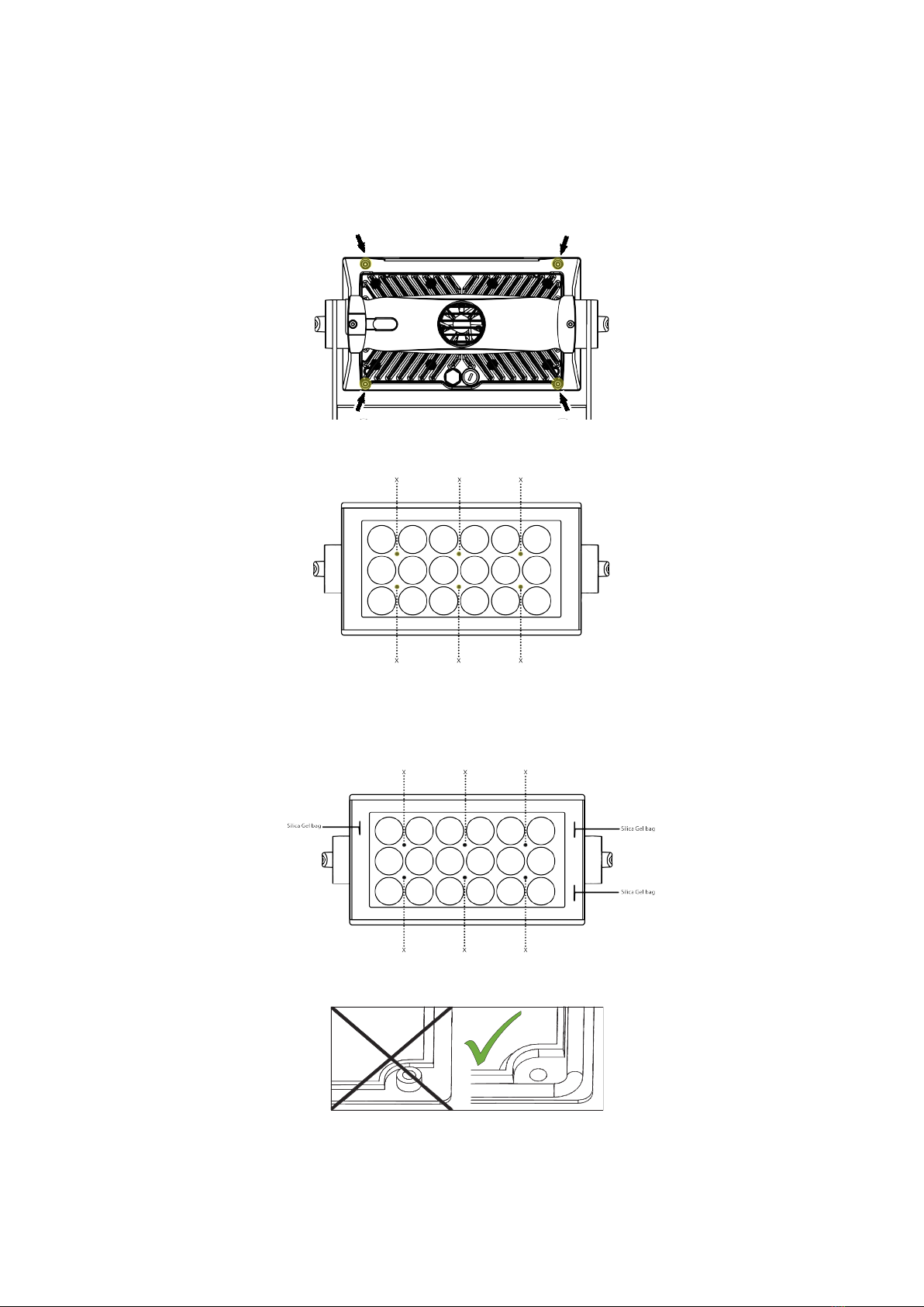
Apart from the lens module, there are no user-serviceable components in the xture. Do not open the P-2 Series, as doing so is likely
to damage the ingress protection. Consult your SGM dealer if the xture operates abnormally, is defective, or, otherwise, in need of
service or repair.
Changing P-2 front lens
Before replacing the lens module, make sure the xture is turned o and cool. Then, take the following steps:
1. Unscrew the highlighted screws with a TX20 screwdriver.
2. Dismantle the front and unscrew the highlighted front plugs with an Unbrako 6 / HOP6 Allen key.
3. Take out the lens module.
4. Place the new lens on the PCB print spacers and carefully press the lens module in place.
5. Screw in the highlighted front plugs with an Unbrako 6/ HOP6 Allen key (Nm 1,0) and place three Silica Gel bags (not
included in lens kit) as shown below.
6. Place the sealing frame facing upwards (see below) on top of the lens module.
7. Place the front assembly on top of the sealing frame.
8. Screw in the highlighted screws with a TX20 screwdriver (Nm 0,7) - see step 1.
9. Check that the sealing frame (gasket) is evenly visible all the way around the lens module.
10. Vacuum test the xture after replacing the lens module to verify that the validity of ingress protection (IP) is kept - see “SGM
Vacuum Test kit” on page 21.
Service
Figure 24: P-2 Changing lens module I
Figure 25: P-2 Changing lens module II
Figure 26: P-2 Changing lens module III
Figure 27: P-2 Changing lens module IV
Other manuals for P Series
3
This manual suits for next models
2
Table of contents
Other SGM Dj Equipment manuals


