SGM P-6 User manual
USER
MANUAL
P-6
Distributor:
www.techni-lux.com
Phone: 407-857-8770
Fax: 407-857-8771

2
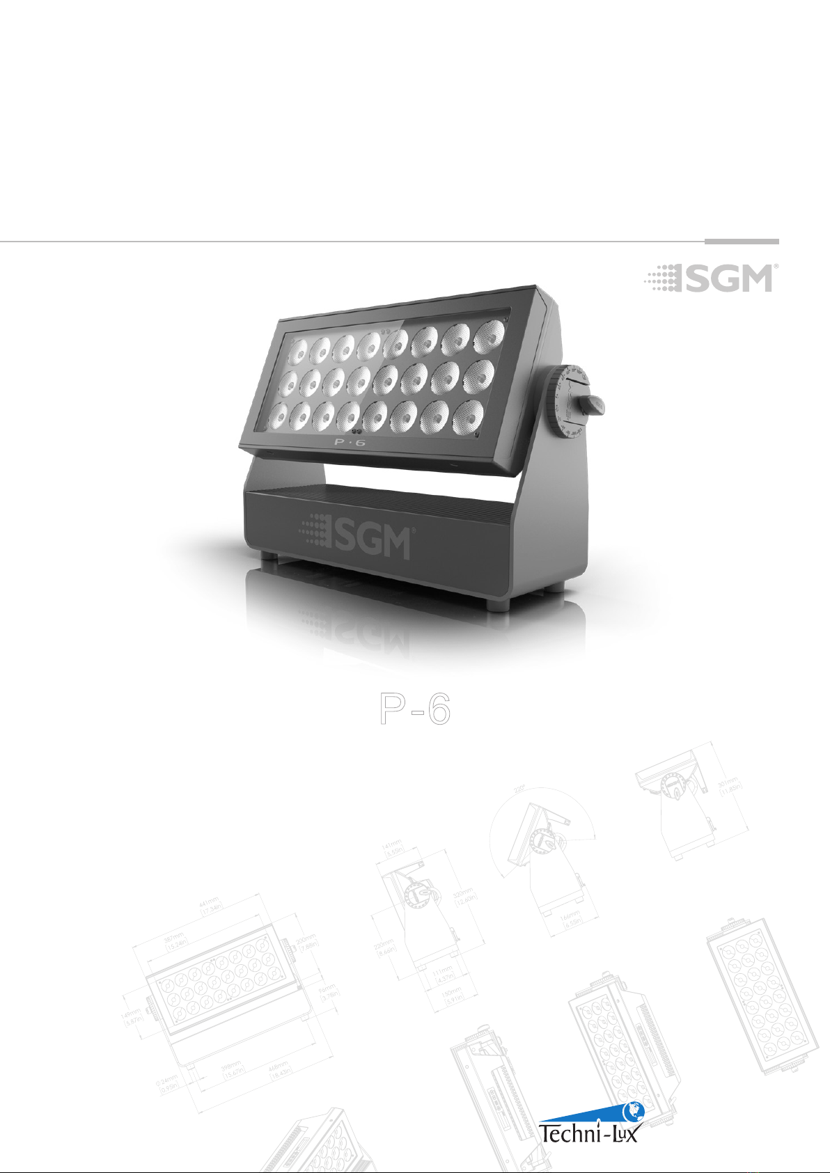
P-6 Dimensions
All dimensions in millimeters and inches. Drawing not to scale.
P-6
USER MANUAL REV. A
© 2018 SGMTM. The information in this document is subject to change without notice. SGM and all afliated
companies disclaim liability for any injury, damage, direct or indirect loss, consequential or economic loss, or
any other loss occasioned by the use of, inability to use, or reliance on the information contained in this manual.
The SGM logo, the SGM name, and all other trademarks in this document pertaining to SGM services or SGM
products owned or licensed by SGM, its afliates and subsidiaries.
English edition
This manual covers installation, use, and maintenance of the SGM P-6.

3
Contents
Safety information.....................................................................................................................4
Overview .................................................................................................................................5
Preparing for installation............................................................................................................6
Installing / rigging the P-6 ..........................................................................................................6
Tilt Lock ..................................................................................................................................7
Connecting AC power................................................................................................................7
Conguring the device...............................................................................................................8
Connecting to a DMX control device ............................................................................................8
Conguring the device for DMX control........................................................................................9
Using standalone operation......................................................................................................10
Setting a static color manually .................................................................................................11
Fixture properties ...................................................................................................................11
Control menu .........................................................................................................................12
RDM......................................................................................................................................13
Troubleshooting .....................................................................................................................13
Accessories ...........................................................................................................................14
Maintenance...........................................................................................................................15
Fixtures and accessories .........................................................................................................16
Support hotline.......................................................................................................................16
Approvals and certications.....................................................................................................16
User Notes.............................................................................................................................17

4
Safety information
• Do not open the device; there are no user-serviceable parts inside.
• Ensure that power is cut off when wiring the device to the AC mains supply.
• Ensure that the device is electrically connected to earth (ground).
• Do not apply power if the device or mains cable is in any way damaged.
• Do not immerse the xture in water or liquid.
DANGER! Risk of electric shock. Do not open the device.
• Install in a location that prevents accidental contact with the device.
• Install only in a well-ventilated space.
• Install at least 0.3 m (12 in.) away from objects to be illuminated.
• Install only in accordance with applicable building codes.
• Ensure a minimum clearance of 0.3 m (12 in.) around the cooling fans.
• Do not paint, cover, or modify the device, and do not lter or mask the light.
• Keep all ammable materials well away from the device.
• Allow the device to cool for 15 minutes after operation before touching it
CAUTION: Exterior surface temperature after 5 min. operation = 49 °C (120 °F). Steady state = 59 °C (138 °F).
WARNING! Take measures to prevent burns and re.
• Do not look directly at the light source from close range.
• Take precautions when working at height to prevent injury due to falls.
• For Permanent Outdoor Installations (POI), ensure that the xture is securely fastened to a load-bearing surface with suitable
corrosion-resistant hardware.
• For a temporary installation with clamps, ensure that the quarter-turn fasteners are turned fully and secured with a suitable
safety cable.
• For elevated installations, secure the xture with suitable safety cables, and always comply with relevant load
dimensioning, safety standards, and requirements.
• The standard safety wire cable must be approved for a safe working load (SWL) of 10 times the weight of the xture, and
it must have a minimum gauge of 4 mm.
WARNING! Take measures to prevent personal injury.
WARNING!
Read the safety precautions in this section before installing, powering, or operating
this product.
SGM luminaries are intended for professional use only. They are not suitable for household use.
Les luminaires SGM sont impropre à l’usage domestique. Uniquement à usage professionnel.
Review the following safety precautions carefully before installing or operating the device.

5
The P-6 is an RGBW LED luminaire with high output, designed for multiple applications, including applications where wireless oper-
ation is essential.
P-6 features:
• Powerful all-in-one 475 W light xture with 6 individually controllable segments, weighing around 12 kg.
• A wash light, a strobe light, a ood light, a pixel light, and a blinder with a non-fading continuous output.
• IP66-rating enable operation in all kinds of environmental settings and in temperatures from -40C to 50C.
• Fully adjustable CTC from 2,000K to 10,000K.
• Built-in wireless DMX and preset-able standalone programs.
• Fully RDM implemented.
• Different beam angles available via magnetic easy-t holographic lter frames
• Integrated handle eases the transport, rigging, and positioning of the luminaire.
• Rubber feet meant for delicate surfaces, and prevents xture from sliding.
Overview
A: Rubber feet
B: Power in and out
C: GORE-TEX membrane
D: DMX in and out
E: Handle
C
D
B
F: OLED Display panel
G: Barndoors aachment points (x2)
H: Safety wire aachment point
I: Holes for omega bracket (x6)
E
F
I
H
A
G
P 6
Parts identication and terminology
Figure 1: Parts identication and terminology

6
Unpacking
Unpack the device and inspect it to ensure that it has not been damaged during transport.
The P-6 is shipped with:
• One Neutrik TRUE1 power input connector, 2 m (78 in.)
• Two Omega brackets with 1/4-turn fasteners
Location / application
The xture is IP66-rated and designed for both indoor and outdoor events. This means that it is protected from:
• Dust, to the degree that dust cannot enter the device in sufcient quantities as to interfere with its operation.
• Pressure jets of water from any direction.
When selecting a location for the device, ensure that:
• It is situated away from public thoroughfares and protected from contact with people.
• It is not immersed in water or exposed to high-pressure water jets.
• It has adequate ventilation.
When using the xture for outdoor events, ensure that:
• For wireless DMX or standalone operation, the protective cover is securely mounted in any unused DMX connectors.
• For cabled DMX operation, the DMX out of the last xture is terminated with a 120 Ohm resistor between pin 2 and 3
(according to the RS485 standard), and the DMX out is properly sealed, in accordance with the IP65 requirements.
A maximum of 32 xtures can be connected to the same DMX link.
Transportation
Always use the supplied packaging or suitable ight case for transportation and storage.
Never carry the xture by connected cables or wires; use the handle.
Preparing for installation
The P-6 may be installed in any orientation and it might take up to 3 omega brackets per
xture. Always use omega brackets to rig the xture and lock the bracket with the 1/4-turn
fasteners.
Please note:
The 1/4-turn fasteners are only locked when turned fully clockwise.
Rigging process
Start the rigging process by blocking the lower working area, and make sure the work is
performed from a stable platform.
1. Check that the clamp is undamaged and can bear at least 10 times the weight of
the xture. Check that the structure can bear at least 10 times the weight of all
installed xtures, lamps, cables etc.
2. Bolt the clamp securely to the omega bracket with a M12/ ½” bolt (min. grade 8.8)
and a lock nut.
3. Align the omega bracket with the two 1/4 turns in the base. Insert the fasteners into
the base bracket, and turn both levers a full1/4-turn clock wise to lock.
4. Working from a stable platform, hang the xture on a truss or other structure.
Tighten the clamp.
5. Install a safety wire that can bear at least 10 times the weight of the xture. The
safety wire attachment point is designed to t a carabiner.
6. Verify that there are no combustible materials, cables, or surfaces to be illuminated
within 0.3 m (12 in.) of the xture.
7. Check that there is no risk of the head/yoke colliding with other xtures or
structures.
Installing / rigging the P-6
Holes for omega bracket
Omega bracket
Figure 2: Base with omega bracket

7
WARNING! Always secure an elevated P-6 with a safety wire
Fasten a safety wire (not shown) between the load-bearing support structure and the safety wire attachment point on the device.
The safety cable (not included in the package) must:
• Bear at least 10 times the weight of the device (SWL).
• Have a minimum gauge of 4 mm.
• Have a maximum length (free fall) = 30 cm (12 in.).
CAUTION!!
• Always use a safety wire.
• Make sure the slack of the safety wire is at a minimum.
• Never use the handle for secondary attachment. Figure 3: Safety wire attachment point
The P-6 can be tilted from 0° - 120°. To adjust the tilt angle, loosen both tilt wheels, one on each
side, adjust the tilt to the angle requested, and re-tighten the wheels. There is no need for any
special tools to tighten the wheels. If you cannot feel resistance when tilting the xture, you might
not have loosened the wheels enough.
Scale function
The P-6 comes with a scale function, which eases the adjustment to the tilt desired.
The pitch indicator in the wheel shows the current angle of inclination.
CAUTION!!
If the xture has been operating, always allow it to cool for 15 minutes before handling.
Exterior surface temperature after 5 min. operation = 49 °C (120 °F). Steady state = 59 °C (138 °F).
Tilt Lock
Pitch angle
indicator
Connecting AC power
The P-6 can operate on any 100–277 V, 50/60 Hz AC mains power supply.
Connect the xture to AC power using the supplied cable with Neutrik powerCON TRUE1 NAC3FX-W (supplied with the xture) or
similar with a maximum of 20 A, to ensure the correct ingress protection (IP-rating).
For a temporary outdoor installation, the mains cable must be tted with a grounded connector intended for exterior use. The xture
must be grounded/earthed and able to be isolated from AC power. The AC power supply must incorporate a fuse or circuit breaker
for fault protection.
CAUTION!!
Do not open the xture to replace the supplied power cable.
Do not connect the xture to an electrical dimmer system, as doing so may cause damage.
After connecting the P-6 to power, run the on-board test by selecting TEST → AUTOMATED TEST in the menu to ensure that the
xture and each LED are functioning correctly. Please see “Control Menu” on page 13.
PLEASE NOTE:
The protective caps must be securely mounted on any unused DMX connectors in order to maintain the IP66-rating.
Figure 4: Tilt lock
The fixture must be grounded/
earthed and be able to be isolated
from AC power. The AC power
supply must incorporate a fuse or
circuit breaker for fault protection.
Color
Black
White
green/yellow
Conductor
live
neutral
ground (earth)
Symbol
or
L
N
Wire
Figure 5: Connecting AC Power
8
The P-6 is controllable using a DMX control device, and it can be connected using either a DMX cable or via the xture’s
built-in LumenRadio CRMX wireless receiver system.
If using a cabled DMX system, connect the DMX IN cable to the input connector and DMX OUT cable to the output. Both connectors
are placed on the rear of the xture’s base (chassis mounted male 5-pin XLR connectors).
For outdoor events, use at least IP65-rated XLR connectors. If using a wireless DMX system, remember to use the protective caps
in any unused DMX connector in order to maintain the xture’s IP-rating.
Connecting to a DMX control device
Conguring the device
The P-6 can be set up by using the control panel and OLED multi-line display at the top of the xture’s head or through RDM.
The OLED display is the human interface of the xture, as it displays the current status and menu of the xture. The display panel
can be used to congure individual xture settings, check the xture’s wireless status, conrm the rmware version, and read error
messages.
The complete list of the menu and all commands available are listed in “Control Menu” on page 12.
Before turning on the P-6, make sure the Neutrik TRUE1 power in cable is properly connected. To turn off the device, simply
disconnect the Neutrik TRUE1 power in cable. When the xture is powered on, it boots and resets before displaying the currently
selected operating mode and the DMX start address. Navigate through the menus and options using the arrow buttons, and select
items using the ENTER button.
DMX
8
ESC ENTER
6CH MODE
(7)
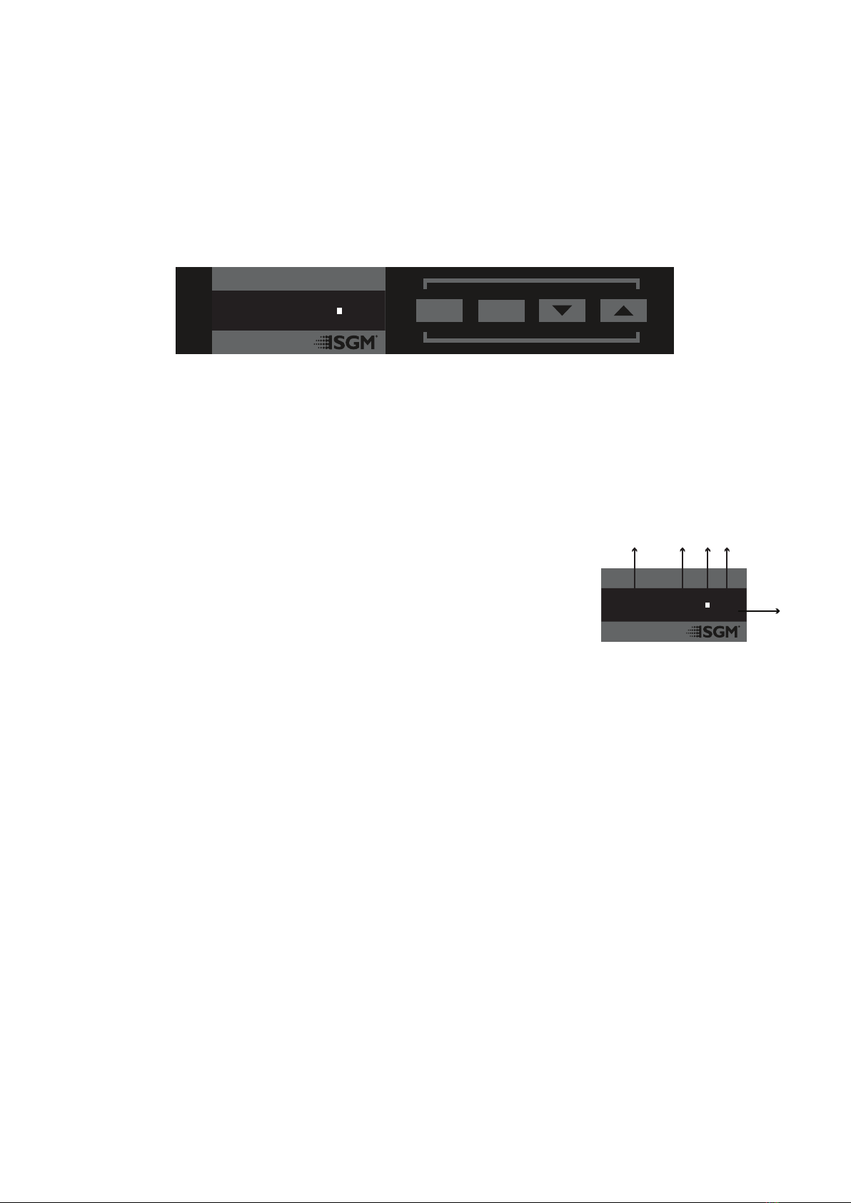
Figure 6: OLED display and control panel
Using the display panel
• Press the ‘ENTER’ button to access the menu or make a selection.
• Press the arrow buttons to scroll up and down in the menus.
• Press the ‘ESC’ button to take a step back in the menu.
Display
A - Operational mode (quick color, stand-alone, or DMX mode).
B - DMX address.
C - External data indicator (if DMX control is active).
D - External data protocol (CRMX™ or DMX).
E - Next available DMX address depending on the xtures DMX footprint.
Please note: by default, the xture is set to be controlled in DMX mode.
Error Indicator
If any errors are detected, the message ‘ERR’ will be ashing in the display for easy detection.
To read the error message, select ENTER → INFO → ERRORS in the menu.
Shortcuts
• ESC + ENTER: Press ENTER to conrm factory defaults.
• ESC + UP: Display OFF.
• ESC + DOWN: Set up new DMX address; keep ESC and press ENTER to conrm.
• UP + DOWN arrows simultaneously = ip the display upside-down.
Figure 7: Display view
DMX
8
6CH MODE
(7)
A B C D
E

9
Connecting a wireless transmitter
The P-6 is designed to look for wireless transmitters in ‘connect’ state, when this option is not yet enabled.
To connect the P-6 to a wireless transmitter:
• Log off the currently paired wireless transmitter - see below “Disconnecting a wireless transmitter”.
• Press the connect button on the wireless transmitter.
• Conrm that the xture has paired with the wireless transmitter.
Disconnecting a wireless transmitter
To disconnect the xture from the currently paired wireless transmitter, go to SETTINGS → WIRELESS DMX → LOG OFF.
Signal priority
The P-6 can be paired to an active wireless transmitter as soon as it is connected to a cabled DMX. The xture will prioritize cabled
DMX over wireless DMX.
The active input type is displayed under the wireless signal strength indicator. The signal strength can also be checked via RDM data
by using a external RDM device (e.g. the SGM A-4).
About DMX
The P-6 can be controlled using signals sent by a DMX controller on a number of DMX channels. DMX is the USITT DMX512-A
standard, based on the RS-485 standard. The signal is sent as DMX data from a console or a controller, to the xture(s) via a shielded
twisted pair cable designed for RS-485 devices.
The cables are daisy chained between the xtures, and up to 32 xtures can be connected on the same DMX link. Up to 300 meters
(1000ft.) of cable is achievable with high quality DMX cables. All DMX links must be terminated in the last xture by connecting a DMX
termination plug to the last xture´s 5 pin DMX out connector.
PLEASE NOTE:
• Standard microphone cable is not suitable for transmitting DMX.
• Up to 32 xtures can be linked to the same DMX chain. Additional xtures will overload the link.
• The last xture must always be tted with a DMX termination plug to the xture’s DMX out.
Set/edit DMX address
The DMX address is shown on the OLED display in the control panel.
To change the address setting, press the up and down arrows. When the desired address is
displayed, press ENTER to save the setting.
For your convenience, the next available DMX address is displayed to the right.
See instructions on how to use the display panel in “Conguring the device” on page 8.
The P-6 also offers the option to set the DMX address through RDM.
DMX modes
The P-6 operates in different modes. All DMX charts are available at www.sgmlight.com under the respective products, or upon
Conguring the device for DMX control
DMX
8
6CH MODE
(7)
DMX address
Next
available
DMX
Figure 8: Set/edit DMX address
10
DMX Start address
The P-6 can be operated in different DMX modes. For any of the modes, the rst channel used to receive data from a DMX control device
is known as the DMX start address.
For independent control, each P-6 must have a DMX start address set. For example, if the rst P-6 is set to 6ch CTC DMX mode with a
start DMX address of 113, the following P-6 in the DMX chain should be set to a DMX address of 119. As the rst xture uses the prior
6 DMX channels, including channel 113, the next available channel is 119 (113+6=119 >> 119).
If two or more xtures of the same type have the same DMX address, they will behave identically. Incorrect settings will result in
unpredictable responses from the lighting controller. Address sharing can be useful for diagnostic purposes and symmetrical control.
NOTE!!
When using power link connection, make sure the maximum power capacity is not exceeded in order to avoid short-circuit
and damaging of the xture.
·
·
Max. 32 units/DMX line
1 2 xx
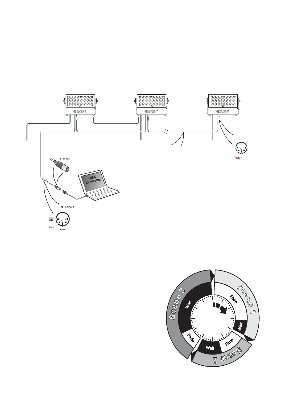
CONNECTION DIAGRAM
P
•
6
SGM Light A/S · Sommervej 23 · 8210 Aarhus V · Denmark
Tel +45 70 20 74 00 · info@sgmlight.com · www.sgmlight.com
SGM_P-6 (Rev.1)
100 - 277V AC
50-60 Hz
475 W
100 - 277V AC
50-60 Hz
475 W
100 - 277V AC
50-60 Hz
475 W
DMX Termination
on last fixture DMX out
DATA
GND
DATA -
DATA +
120 Ohm +/- 5%
Max. 6 units/16 A circuit
P 6 P 6P 6
Figure 9: P-6 connection diagram
Standalone operation is not running when the xture is connected to a control device, but it is pre-programmed with a series of up
to 24 scenes, playing continuously in a loop. Up to three stand-alone programs can be dened and run from the menus, and one of
the programs can be set to run by default whenever the xture is powered on.
Each of the three available stand-alone programs contains 24 user-denable
scenes with its own RGB and shutter settings.
Each scene has a denable fade-in time for the transition from one color to the
next, and a wait (static) time of up to 120 minutes and 59 seconds.
To dene a stand-alone program, press ENTER → MANUAL → EDITOR.
The standalone mode of the xture’s startup is enabled by pressing:
ENTER → SETTINGS → STARTUP MODE → SELECT STARTUP MODE →
STANDALONE.
To select the xture’s startup program, press:
ENTER → SETTINGS → STARTUP MODE → STARTUP PROGRAM.
The chosen program will run its length cyclically whenever the xture is
powered on.
To run an internal program, go to:
ENTER → MANUAL → RUN PROGRAM.
To stop an active internal program, go to:
ENTER → MANUAL → STOP PROGRAM.
Using standalone operation
Figure 10: Standalone operation

11
Setting a static color manually
The P-6 can be congured to display a predened and static color.
To set up a static color, select ENTER → MANUAL → QUICK COLOR.
Note that once the MANUAL → QUICK COLOR settings are changed, the xture will, by default, be set to automatically start in quick
color mode whenever it is powered on. This can be reset through the menu SETTINGS → STARTUP MODE → SELECT STARTUP
MODE.
The current quick color program can always be stopped going to:
ENTER → MANUAL → STOP PROGRAM
See “Control menu” on page 13 for detailed information.
Factory default
When restoring factory defaults in the P-6, the following settings will be set:
• DMX address = 1
• DMX mode = Default mode (6 channel)
• Startup mode = DMX
• Display saver = Off
• Flip screen = Off
• RDM device label set to = Fixture type name
• Internal program reset
Effects
The P-6 is a luminaire with 24 high-power RGBW 24W LEDs, divided in 6 individually controllable segments, which generates
wide-ranging color effects and pixel-mapping combinations for creative lighting designs.
Individual xture settings
Flipping the OLED display
If the xture is installed hanging upside down, it might be useful to ip the display so that it is easier to read.
To ip the display, press ENTER and select SETTINGS → FLIP DISPLAY, or press the up and down buttons on the control panel at
the same time.
Setting the OLED display saver
By default the OLED display dims down after a short period when the control panel is not in use. The display can also be set to turn off
completely, ideal when a pitch-black environment is required. Pressing any key will always turn on the display or restore it to normal
brightness.
To congure the display settings, press ENTER → SETTINGS → DISPLAY SAVER.
NOTE: To avoid the risk of display deterioration caused by long term use, it is recommended to select the setting → DISPLAY OFF.
Setting the fan mode
For operating environments where low-noise is a requirement, or where the xture will be operating in high temperatures, it is possible
to adjust the default fan speed by going to SETTINGS → FAN MODE in the menu.
Fixture properties
Figure 11: P-6 Pixel segments
Pixel 1
Pixel 3
Pixel 5
Pixel 2
Pixel 4
Pixel 6

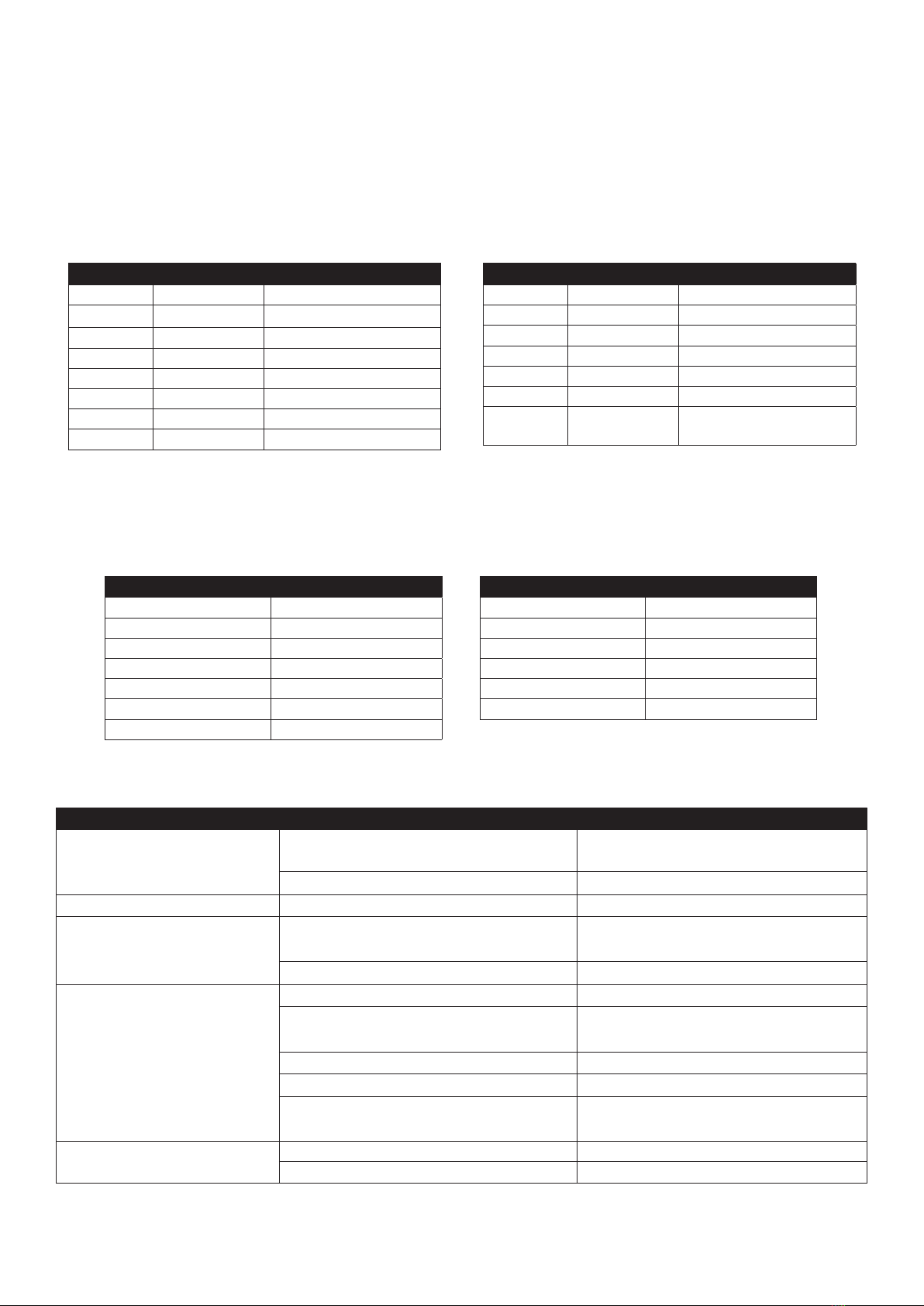
12
Level 1 Level 2 Level 3 Function
Mode Select Mode - Select DMX mode
Info Product Type - Displays product type
Firmware Version -Displays installed rmware version
Serial Number - Displays SGM serial#
RDM ID - Displays RDM ID. (Unique RDM ID for identication )
DMX View Up to 504 DMX addresses Displays received DMX levels
Temperatures Mainboard
Displays xture temperatures
LED Left
LED Right
Humidity head
Fan Left RPM
Fan Right RPM
Wireless signal
Wireless paired
Light pwn
Humidity base
Base
Power on time - Displays xture total power on time
LED On Time - Displays LED total power on time. (R, G, B, W)
Errors - Displays error codes
Settings Wireless DMX Wireless log off Sends Log off command to the CRMX System
Signal strength Displays strength of the wireless connection
Startup Mode Select Startup Mode Default operating mode when xture is powered on: 1. DMX (factory default)
2. Stand-alone
3. Quick Color
Startup Program Stand-alone program 1, 2 or 3.
Only used if the startup mode is set to “stand-alone”. Program 1 is default.
Flip Display Disable Selects normal control panel display.
Enable Flips control panel display.
Display Saver Display Off Turns off the OLED display when the control panel is not in use.
Display Dim Dims the OLED display when the control panel is not in use.
Fan Mode Standard Adjust fan speed relative to internal xture temperature.
Silent Low fan speed for quiet operation.
Max Power High fan speed for maximum cooling effect.
Factory Default -Reset the xture to factory default settings.
Manual Quick Color Red Static quick color - red mix (0-255). Sets xture to quick color startup mode.
Green Static quick color - green mix (0-255). Sets xture to quick color startup mode.
Blue Static quick color - blue mix (0-255). Sets xture to quick color startup mode.
Run Program 1, 2 or 3 Runs internal sequence 1,2 or 3.
Stop Program - Stops current running internal sequence or Quick Color.
Editor Program Currently selected program (1, 2 or 3).
Scene Currently selected scene (1-24).
Red Red value in currently selected scene (0-255).
Green Green value in currently selected scene (0-255).
Blue Blue value in currently selected scene (0-255).
Shutter Shutter setting in currently selected scene (0-255). (According to latest DMX chart)
Fade Time (Min.) Fade-in (transition) time to current scene in min. (0-511).
Fade Time (Sec.) Fade-in (transition) time to current scene in sec. (0-59).
Wait Time (Min.) Wait (static) time in current scene in min. (0-998).
Wait Time (Sec.) Wait (static) time in current scene in sec. (0-59).
Test Off -Stops test sequence execution.
Automated Test - Initiates a self-test sequence.
Display Test - Service use only.
Control menu
13
Supported RDM functions
The P-6 features support for various RDM functions.
RDM (Remote Device Management) is a protocol enhancement to USITT DMX512 that allows bi-directional communication between
the xtures and the controller over a standard DMX line. This protocol will allow conguration, status monitoring, and management.
You will need a RDM controller to get control over the supported parameters. See the tables below for supported RDM functions.
RDM functions
RDM
Name Sensor Type
Mainboard Temperature
LED Left 1 Temperature
LED Left 2 Temperature
LED Left 3 Temperature
LED Right 1 Temperature
LED Right 2 Temperature
LED Right 3 Temperature
Name Sensor Type
Humidity Head Other
Wireless Signal Strength Other
Wireless Paired Other
Light PWM Other
Humidity Base Other
Base Temperature
PID Actions allowed Name
0x0082 - Device Label
0x0081 - Manufacturer Label
0x00E0 - DMX Personality
0x00E1 - DMX Personality description
0x0200 -Sensor Denition
0x0201 - Sensor Value
0x0080 - Device Model Description
0x0400 - Device Hours
PID Actions allowed Name
0x0051 - Parameter Description
0x0501 - Display Level
0x0500 - Display Invert
0x0090 -Factory Defaults
0x1001 - Reset Device
0x8060 GET Serial Nr.
0x8625 GET / SET FAN 0=AUTO 1=LOW
2=HIGH 3=FULL
Please note: The RDM controller communicates with the xtures to show only the available options for each RDM function. The table is subject to change without notice.
Sensors
RDM enables various sensor readouts for remote device monitoring. See the table below for sensors and sensor types.
Please note: The RDM controller communicates with the xtures to show only the available sensors for this xture. The table is subject to change without notice.
Troubleshooting
Problem Potential cause(s) Remedies
Fixture does not respond or appears to be
completely dead.
No power to the xture. Conrm that the power is switched on, conrm that the
cables are plugged in.
Main fuse is blown. Contact SGM support or certied SGM service partner.
Fixture suddenly turned off. Power was turned off. Check the power supply, switches and breakers.
Fixture suddenly stopped responding. The wireless transmitter or connections, was disconnected/
tampered with.
Inspect the wireless transmitter and connections.
DMX cables were disconnected. Inspect DMX cables.
Fixture operates irregularly / abnormal. DMX cable polarization is inverted (pin 2 + 3). Install a phase-inverter or replace cables.
DMX link is not terminated. Install a XLR 120ohm DMX termination at the end of
the DMX link.
Corrupted DMX cable. Replace or repair defective cables and/or connections.
The xture operates an internal program. Go to MENU → MANUAL → STOP PROGRAM
A corrupted xture generates noise/disruptions on the DMX
link.
Track and isolate the corrupted xture.
Color is uneven. The minimum values are out of calibration. Contact your local SGM dealer or support@sgmlight.
The SGM Calibration Data set has been lost. Contact your local SGM dealer or support@sgmlight.
14
Accessories
The P-6 can be used with various accessories such as cables, barndoors, and lter frames.
To get to know all the available P-6 accessories, visit www.sgmlight.com or contact your local SGM dealer.
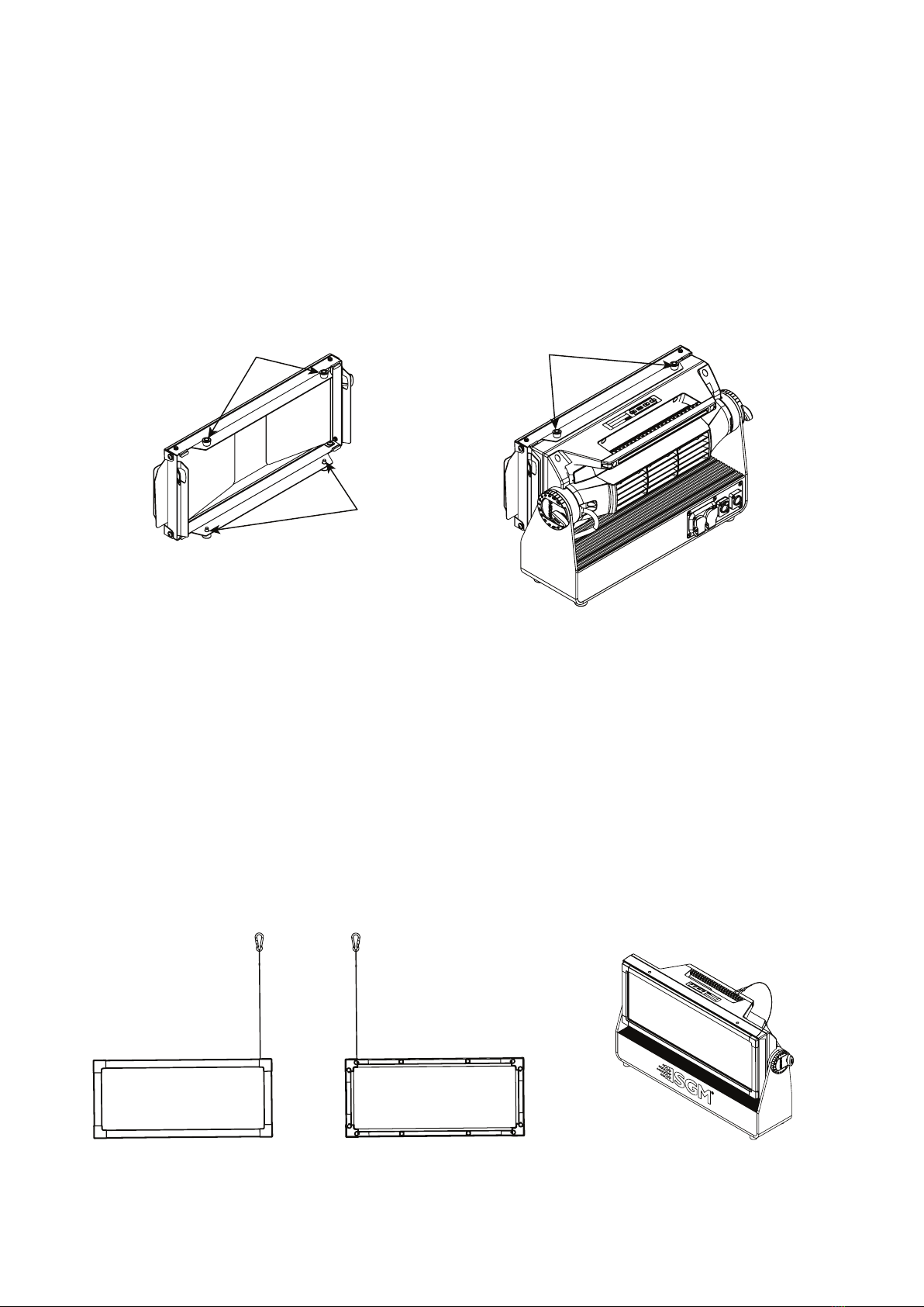
Barndoors
The P-6 features 4-way and 8-way barndoors. The barndoors are designed and intended to be mounted on the xture without the
use of any tools.
To install the barndoors:
1. Attach the lower plug-in pins to the bottom part of the P-6 front
2. Pull the two upper lock pins and t the upper part of the barndoor in the P-6 head
3. Release the lock pins and check the lock pins are correctly in place
Filter frames
The P-6 features various optional, magnetic holographic lter frames:
• Medium angle (19°)
• Wide angle (45°)
• Elliptical wide angle horizontal (63°x12°)
• Elliptical wide angle vertical (12°x63°)
• Empty lter frame for custom lters
The lter frames are easily mounted due to their magnetic properties. To install them, it’s only required to position the lter frame in
front of the light, and it quickly snaps into place.
The frames are tted with a safety wire to secure the frame to the handle of the P-6.
A lter frame can be mounted simultaneously with a barndoor.
For further information and other possibilities visit www.sgmlight.com or contact your local SGM dealer.
Upper lock pins Attachment
points
Lower
lock pins
Filter frame front view Filter frame back view
P-6 with lter frame
Figure 12: P-6 Barndoors
Figure 13: P-6 Filter frames

15
Upgrading the rmware
The rmware installed in the xture can be identied in two ways:
• When powering on the xture, the display shows the current installed rmware version
• Going to the MENU → INFO → SOFTWARE VERSION
We recommend that the xture’s rmware is always up-to-date. The latest rmware version is available for download under the
respective product at www.sgmlight.com.
To update your P-6 with the latest rmware use an SGM USB 5-Pin-XLR uploader cable (available from your nearest SGM dealer)
and a Windows-based computer with the SGM Firmware Tool software installed (also available for download at www.sgmlight.com).
Additionally, the Firmware Tool software offers a simple DMX controller featuring 512 DMX channels for test purposes.
Cleaning
SGM luminaires with IP66-rating do not need any cleaning procedures inside the xture. However, cleaning the front lens may be
needed to achieve the maximum light output after exposure to dust, sand, or dirt. Exterior housing can also be cleaned to get a better
look. To maintain adequate cooling, fans must be cleaned periodically.
Whenever necessary, clean the P-6 using a soft cloth dampened with a solution of water and a mild detergent. Do not use products
that contain solvents, abrasives, or caustic agents for cleaning, as they can cause damage to both hardware, cables, and connectors.
The level of cleaning required will vary greatly depending on the operating environment and installation. Therefore, it is recommended
to do frequent check-ups the rst few weeks of operation to see how often cleaning is necessary.
Maintenance
Figure 15: SGM Firmware tool

16
Fixtures and accessories
The P-6 can be used with a variety of accessories.
Contact your local SGM dealer to get the latest pricing and news about available accessories.
Please note: the listed below are subject to change without notice.
Ordering information
P-6, Std, BL...................................................................................................................................................................... P/N: 80031650
P-6, Std, WH..................................................................................................................................................................... P/N: 80031651
P-6, Std, CU..................................................................................................................................................................... P/N: 80031652
P-6 Accessories
2 m power cable with Neutrik TRUE1 power connector..................................................................................................... P/N: 07860040
2 x Omega brackets, BL / WH......................................................................................................................... P/N: 83060602 / 83061206
SGM USB uploader cable..................................................................................................................................................P/N: 83062011
Filter frame - Elliptical horz wide angle, BL - P-6 series.......................................................................................................P/N: 83061168
Filter frame - Elliptical vert wide angle, BL - P-6 series........................................................................................................P/N: 83061169
Filter frame - Medium angle, BL - P-6 series.......................................................................................................................P/N: 83061170
Filter frame - Wide angle, BL - P-6 series............................................................................................................................P/N: 83061171
Filter frame - without lter, BL - P-6 series...........................................................................................................................P/N: 83061172
Barndoor 4-way, P-6, BL....................................................................................................................................................P/N: 83061173
Flightcase for 4 pcs of P-6 incl. accessories...................................................................................................................... P/N: 82051507
Support hotline
SGM offers 24/7 technical support hotline.
Worldwide: +45 3840 3840
US: +1 877 225-3882
Certied to CSA No. 166
Conforms to 73
Conforms to 2014/35/EU: Low Voltage Directive
Conforms to 2014/30/EU: EMC Directive
Conforms to 2011/65/EU: RoHS2 Directive
Approvals and certications
The information in this document is subject to chance without notice. For the latest information, see www.sgmlight.com.

17
User Notes
________________________________________________________________________________________________________
________________________________________________________________________________________________________
________________________________________________________________________________________________________
________________________________________________________________________________________________________
________________________________________________________________________________________________________
________________________________________________________________________________________________________
________________________________________________________________________________________________________
________________________________________________________________________________________________________
________________________________________________________________________________________________________
________________________________________________________________________________________________________
________________________________________________________________________________________________________
________________________________________________________________________________________________________
________________________________________________________________________________________________________
________________________________________________________________________________________________________
________________________________________________________________________________________________________
________________________________________________________________________________________________________
________________________________________________________________________________________________________
________________________________________________________________________________________________________
________________________________________________________________________________________________________
________________________________________________________________________________________________________
________________________________________________________________________________________________________
________________________________________________________________________________________________________
________________________________________________________________________________________________________
________________________________________________________________________________________________________
________________________________________________________________________________________________________
________________________________________________________________________________________________________
________________________________________________________________________________________________________
________________________________________________________________________________________________________
________________________________________________________________________________________________________
________________________________________________________________________________________________________
________________________________________________________________________________________________________
________________________________________________________________________________________________________
________________________________________________________________________________________________________
________________________________________________________________________________________________________
________________________________________________________________________________________________________
________________________________________________________________________________________________________
________________________________________________________________________________________________________
________________________________________________________________________________________________________
________________________________________________________________________________________________________
________________________________________________________________________________________________________
________________________________________________________________________________________________________
________________________________________________________________________________________________________

Other manuals for P-6
1
This manual suits for next models
2
Table of contents
Other SGM Dj Equipment manuals


