SGM LB-100 User manual

LB·100
LED BALLS
2
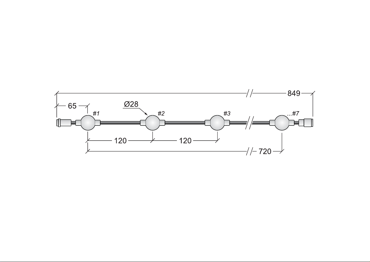
Dimensions of LB-100 LED Balls
All dimensions in mm.
Drawing not to scale.

3
LB-100 LED BALLS
USER MANUAL REV. 2
© 2010-2013 SGMTM,QIRUPDWLRQ VXEMHFW WR FKDQJH ZLWKRXW QRWLFH SGM DQG DOO DI¿OLDWHG
companies disclaim liability for any injury, damage, direct or indirect loss, consequential
or economic loss or any other loss occasioned by the use of, inability to use or reliance
on the information contained in this manual. The SGM logo, the SGM name and all other
trademarNs in this document pertaining to serYices or products by SGM or its af¿liates and
subsidiaries are trademarNs oZned or licensed by SGM or its af¿liates or subsidiaries.
LB-100 LED Balls uk

4
Contents
Safety Information....................................................................................................5
Read the Manual................................................................................................................................................6
Protection from Injury.........................................................................................................................................6
Introduction..........................................................................................................................7
Parts Identi¿cation and 7erminology...................................................................................................................
Features.................................................................................................................................................8
Connections Overview........................................................................................................................................9
Connecting to 6*M 7ouring /(D Driver 7/D6..............................................................................................
8sing custom Sower suSSly and 6*M adaStor caEle....................................................................................
Service................................................................................................................................12
Cleaning......................................................................................................................................................
Troubleshooting.............................................................................................................13
Speci¿cations/%-100 3art 000001...........................................................................14
Users notes........................................................................................................................16

5
Safety Information
• This product is for professional use only. It is not for household use.
This product presents risNs of severe injury or death due to ¿re ha]ards.
• When using a 12V DC custom power supply, always use an AC power source that complies with local building
and electrical codes and has both overload and earth
leakage protection.
• 1ever attempt to bypass the fuse. Always replace defective fuses with ones of the speci¿ed type and rating.
• Verify that the power feed cable is rated for the current draw of all connected ¿[tures. See application informa-
tion on page 11.
• Do not modify the ¿[ture or install other than genuine SGM parts.
• Do not operate the system if the ambient air temperature Tae[ceeds 40 ÛC 104 Û)
WARNING! Read the safety precautions in this section before
installing, powering, operating or servicing this product.

6
Read the manual
5ead this manual before installing or powering the /(D %alls, and follow the safety precautions.
Always observe all warnings in this manual and printed on the system. If you have questions about how to oper-
ate the system safely, please contact your SGM representative.
Protection from injury
• (nsure that any structure used for support as well as all fastened and connected hardware can hold at least 10
times the weight of all supported devices and equipment.
• Use a minimum of two approved secondary attachments such as safety wiresto secure each product as de-
scribed in this manual. Safety wires must be approved by an of¿cial body such e.g. ThVas a safety attach
ment for the weight of all the products it secures. Safety wires must be capable of supporting a static suspended
load ten times the weight of the product.
• Check that all e[ternal covers and rigging hardware are securely fastened.
• %lock access below the work area and work from a stable platform whenever installing, servicing or moving the
product.
Read this manual before installing, powering or servicing.

7
Introduction
PartVidenti¿cation and terminoloJy
See )ig. 1 for part terminology and identi¿cation.
A. 2ne string /(D %alls 7 /(D balls
%. 2ne row of /(D %alls consisting of 1 to strings
Ma[. 56 /(D balls.
Fig.

Features
The SGM /(D %alls form a modular semi-transparent /(D video curtain with a 12cm pi[el pitch, which can be
viewed in a 360angle. 2ne /(D %all driver is capable of producing a seamless image of 6.6 meters vertically
and for as long in the hori]ontal direction as the number of drivers permit )ig.2.
The system features
• 12cm pi[el is capable of producing a seamless image at 3.6m2per Touring /(D driver.
• 5ich 5G%color
• Color resolution of bits per color
• 360° viewing angle
(ach string consists of 7 balls with 5G%color /(Ds and each string connects to both
the driver as well as to the corresponding string with 4 pin RJ765 connectors. As many
as strings can be linked to form a row of strings with a total of 56 balls on each row.
Fig.
6 meters 60 centimeters

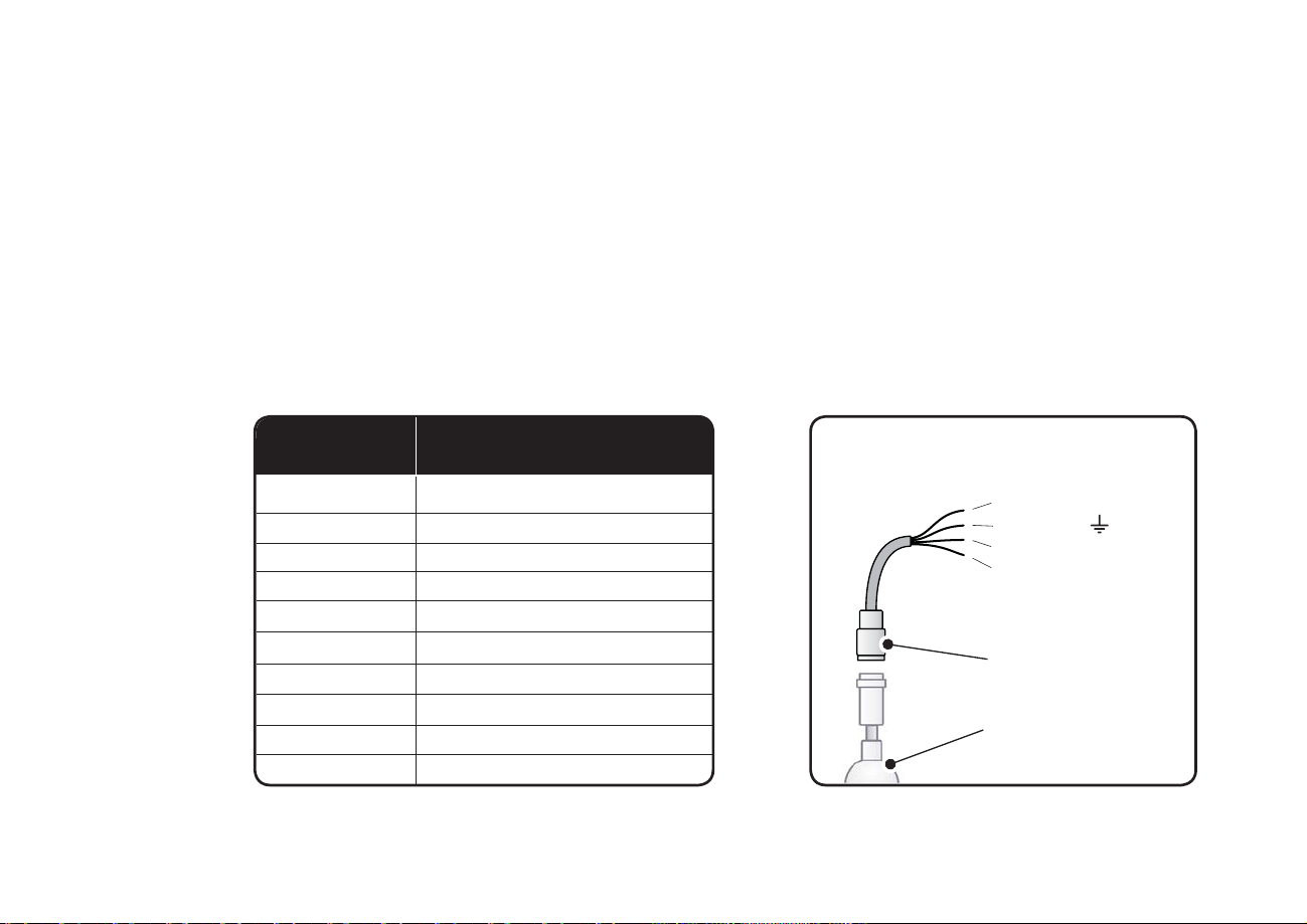
Connections Overview
The /(D ball string has a female 4 pin RJ765 connector at the inlet before ball 1, and a male 4 pin RJ765 con-
nector at the outlet after ball 7. )ig. 3 shows the pin layout.
pin female R-6connector
Connector front shown
Fig. 3

10
&onnectinJto
6G0TourinJ/(' 'riYer
T/'
T/D-612
3art 0070201
11
8sinJ&ustom SoZer suSSly and 6G0adaStor caEle
When e[tending the supply cable between the adaptor 3art 3060201and a user speci¿ed 12VDC 3SU,
make sure to use cables according to speci¿cations in the table below.
When using a 12V DC custom power supply, it must be protected with a T12.5A fuse.
Use only an AC power source that complies with local building and electrical codes and has both overload and
earth leakage protection.
0 - 3
3 - 4,5
4,5 - 6
6 -
- 12
12 - 15
15 - 1
1- 22
22 - 2
2- 32
Cable length
(meters)
Cross sectional area
(mm)
0,5
0,75
1
1,5
2
2,5
3
4
5
6
Adaptor IC-1
Part 836
Red12 V
%lack
GreenData -
%lueData
4 pin RJ765
female connector
/(D light source
/(D %alls shown

12
Service
&leaninJ
Regular cleaning is essential for the /(D %alls performance. Accumulation of dust and dirt degrades the /(D light output.
Cleaning schedules will vary greatly depending on the operating environment, and the installation should therefore
be checked at frequent intervals within the ¿rst few weeks of operation to see whether cleaning is necessary. This
procedure will allow you to assess cleaning requirements in your particular situation. If in doubt, consult your SGM
dealer for a suitable maintenance schedule. Clean the /(D %alls with a soft cloth dampened with a solution of water
and a mild detergent such as car shampoo. Do not use products that contain solvents, abrasives or caustic agents
for cleaning, as they can cause damage to the surface of the balls.

13
Troubleshooting
No light in
one /(D ball
No light in
one string of
/(D balls
/ow light output
from /(D balls
near end of
string
Problem
No DMX signal is
received from source
Defective DMX source
Incorrect addressing
Defective /(D
Defective DMX source
%ad data link
Short circuit at end
connector
Incorrect addressing
Defective /(D
Insuf¿cient voltage
from power source
Probable cause(s) Remedy
Replace DMX source
Check addresses and protocol settings
Replace DMX source
Check addresses and protocol settings
Replace /(D string
Replace DMX source
Inspect RJ765 connectors and correct poor connections
Remove any metal parts causing short circuit at the last
RJ764 pin connector in string
Check addresses and protocol settings
Replace /(D string
Check power source speci¿cations and replace power
source if necessary
Inspect power source for defects and repair or replace
power source
If e[tension cables are used, make sure that they comply with
the speci¿cations described in this manual

14
Speci¿cations /% (Part )
BALL DIMENSIONS
Diameter.......................................................................................................................................................2mm
3i[el pitch............................................................................................................................................................12cm
7 balls string length %alls CC.............................................................................................................................72cm
%all 3i[el weight....................................................................................................................................................20g
INSTALLATION
Orientation........................................................................................................................................Any
AMBIENT OPERATING CONDITIONS
Ma[imum ambient temperature Ta...................................................................................................40 °C 104 °)
Minimum ambient temperature Ta....................................................................................................-10 °C 14 °)
Operating humidity..............................................................................................................................................100%
I3rating................................................................................................................................................................I365
SIGNAL SOURCE
According to standard.........................................................................................................................USITT DMX 512

15
CONNECTIONS
Data input................................................................................................................Male locking 4 pin RJ765 socket
Data output.........................................................................................................)emale locking 4 pin RJ765 socket
ELECTRICAL
3ower supply voltage.................................................................................................................................12V -0.2V
3ower consumption per /%-100 7 pi[els...........................................................................................................5.4W
APPROVALS
Safety........................................................................................................................................................(N 6050-1
(MC.....................................................................................................................................(N 55103-1, (N 55103-2
INCLUDED PARTS
• /(D %alls string, /%-100 3art 000001
• User manual
ACCESSORIES
IC-1, 3ower adaptor cable...............................................................................................................3art 30060201
6Seci¿cations suEject to chanJe Zithout notice

16
Users notes

17

1

1

SGM A/S · Soeren Frichs Vej 51-53 · DK 8230 Aabyhoej · Denmark
Other manuals for LB-100
1
Table of contents
Other SGM Dj Equipment manuals


SGM
SGM SP-6 SIXPACK User manual

SGM
SGM Idea spot 575 User manual

SGM
SGM P-10 User manual

SGM
SGM Giotto profile 400 User manual

SGM
SGM PALCO 3+ User manual

SGM
SGM MOVING HEADS SERIES User manual

SGM
SGM X-5 User manual

SGM
SGM P-5 Wash Light User manual

SGM
SGM P-5 Series User manual

SGM
SGM G-4 RGBAM WASH User manual


