SGS TJH22 User manual

FOR YOUR SAFETY
PLEASE READ THESE INSTRUCTIONS CAREFULLY
AND RETAIN THEM FOR FUTURE USE.
OWNER’S MANUAL
TJH22 PROFESSIONAL
PNEUMATIC JACK

PAGE 3
PAGE 2
SPECIFICATION
Maximum weight capacity: 22 Tonne
Product code: TJH22
Air Pressure 100 - 200 PSI
WARNING
WARNING
Read and understand instructions before use.
Always wear eye/face and hand protection.
Never connect to an air source that is capable of
exceeding 200 psi. Never use oxygen, carbon
dioxide, combustible gases or any bottled gas as
an air source for the tool. Such gases are capable of
explosion and serious injury to persons.
Never overload beyond its capacity.
Always use axle stands.
Use wheel chocks.
Do not exceed the jacks max lift height.
The jack must be supported on a solid level
surface which is free of obstructions.
Maintenance should only be performed by
qualified persons.
WWW.SGS-ENGINEERING.COM

PAGE 5
PAGE 4
Before each use, it’s highly advised to visually
inspect this trolley jack. Abnormalities that should
be checked for every time:
• cracked welds
• leaking fluid anywhere on the trolley jack
• bent parts
• missing parts
• loose parts
• damaged parts
This trolley jack should be taken out of service if it is believed to
have been subjected to an abnormal load or shock.
Owner/operators should be aware that repair of this trolley jack
requires specialist attention in the form of suitable repair equip-
ment and knowledge.
INSPECTION BEFORE EACH USE PURGING YOUR TROLLEY JACK
Sometimes during transport and handling, air gets into the hy-
draulic system causing poor lifting performance. Before the initial
operation purge any air from the system by following these steps:
1. Turn the handwheel 1-1/2 turns counter clockwise.
2. Remove the oil filler plug from the side of the reservoir.
3. Connect the air supply hose lock fitting onto the air inlet, and
open the air valve for a moment to purge air from the system.
4. Turn the handwheel clockwise until snug.
5. Top off the jack reservoir as described below.
6. Replace the oil filter plug.
OIL REPLACEMENT
1. Place jack in an upright position and lower the ram.
2. Remove the oil filler plug.
3. Fill with high quality hydraulic jack oil to the lower rim of the
fill hole.
4. Purge air from the system as above.
5. Top off with more hydraulic oil and replace the filler plug.
WWW.SGS-ENGINEERING.COM

PAGE 7
PAGE 6
ASSEMBLY
Attach Adapter Holder (40) to the Lower Handle (18) with two U-
Bolts (39) and Nuts (23).
Tighten Nuts to secure Adapter Holder to Handle.
ASSEMBLY
Put height adjustment Saddle Adapters (41– 43) into the Adapter
Holder (40) and lock each with an R-Pin (44).
Put the Handle Assembly into Handle Socket and secure with
Bolt (6).
WWW.SGS-ENGINEERING.COM

PAGE 9
PAGE 8
OPERATION
BEFORE USE
1. Make sure the jack and vehicle are on a hard level surface.
2. Always set the vehicle handbrake and chock the wheels.
3. Consult the vehicle owner’s manual to ascertain the location
of jacking points and position the jack beneath the lifting
point.
4. Place jack stands beneath the vehicle at locations recom-
mended by the vehicle manufacturer. Do not work under the
vehicle without the use of jack stands. Jacks are not designed
to maintain heavy loads for long periods of time.
5. Incorporate a filter, regulator with pressure gauge, oiler, in-line
shutoff valve, and quick coupler for best service. An in-line
shutoff ball valve is an important safety device because it con-
trols the air supply even if the air hose is ruptured. The shutoff
valve should be a ball valve because it can be closed quickly.
6. Note: If an automatic oiler system is not used, add a few
drops of Pneumatic Tool Oil to the airline connection before
operation. Add a few more drops after each hour of continual
use.
OPERATION
LIFTING
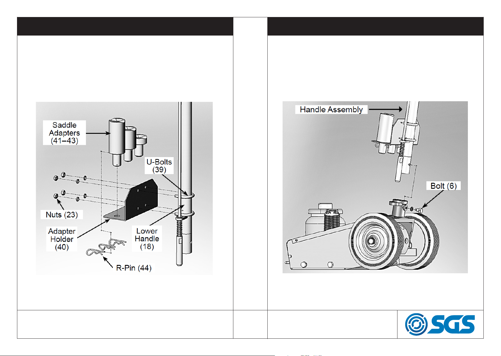
1. Install the handle assembly and turn the handwheel until snug.
2. Adjust the hand angle degree as needed to place the jack in
position under the load.
3. Adjust the extension screw as required. Turn counter clock-
wise to raise and clockwise to lower.
4. Connect the air supply hose lock fitting into the air fitting. The
lever should be off (not in the locked position)
6. Press the lever to the on position and lock using the lock lever.
This provides continuous air to the air motor.
7. Raise the jack by alternately lifting and lowering the handle
assembly.
LOWERING
1. Turn the handle knob clockwise to close the release valve.
2. Pump the handle to lift the vehicle off the jack stands.
3. Remove the jack stands. Do not get under the vehicle while
the vehicle is being lowered.
4. Turn the handle knob slowly counter clockwise to lower the
vehicle onto the ground.
WWW.SGS-ENGINEERING.COM

PAGE 11
PAGE 10
EXAMPLE AIR SETUP
A
Air Hose
Connects air to tool
B
Filter
Prevents dirt and condensa-
tion from damaging tool or
workpiece
C
Regulator
Adjusts air pressure to tool
D
Lubricator (optional)
For air tool lubrication
E
Coupler and Plug
Provides quick connection and
release
F
Leader Hose (optional)
Increases coupler life
G
Air Cleaner / Dryer (optional)
Prevents water vapor from
damaging workpiece
H
Air Adjusting Valve (optional)
For fine tuning airflow at tool
TROUBLESHOOTING
PROBLEM POSSIBLE CAUSE ACTION
Jack will not lift to
full height
Low oil level Check oil level and
refill if necessary
Jack will not hold
load
Release valve not closing,
oil may be contaminated-
pump valves not seal-
ing, cylinder ram may be
binding
Contact customer
service.
Lift arm will not
lower
Cylinder ram binding,
parts may be worn, and/
or internal damage- or a
broken return spring-
or a lift arm linkage bent
or binding
Contact customer
service.
Jack feels spongy
when lifting
Trolley jack may
require an air purge
Purge trapped air
WWW.SGS-ENGINEERING.COM

PAGE 13
PAGE 12
TECHNICAL COMPONENTS TABLE TECHNICAL COMPONENTS (EXPLODED VIEW)
Part Description Part No Part Description Part No
1 Bolt 902354 24 Spring 902377
2 Bolt 902355 25 Tie Rod-3 902378
3 Right Side Plate 902356 26 Screw 902379
4 Circlip 902357 27 Pin 902380
5 Wheel 902358 28 Handle Lever 902381
6 Bolt 902359 29 Handle Sleeve 902382
7 Adjustable Frame 902360 30 Pin 902383
8 Base Plate 902361 31 Knob 902384
9 Left Side Plate 902362 32 Upper Handle 902385
10 Handle Socket 902363 33 Pump Assembly 902386
11 Washer 902364 34 Washer 902387
12 Screw 902365 35 Air Hose 902388
13 Nut 902366 36 Valve Body Assembly 902389
14 Connector 902367 37 Quick Coupler-Male 902390
15 Tie Rod-1 902368 38 Plate 902391
16 Tie Rod-2 902369 39 U-Bolt 902392
17 Screw 902370 40 Adapter Holder 902393
18 Lower Handle 902371 41 Saddle Adapter A 902394
19 Screw 902372 42 Saddle Adapter B 902395
20 Handle Connector 902373 43 Saddle Adapter C 902396
21 Slotted Pin 902374 44 R-Pin 902397
22 R-Pin 902375 45 Saddle Adapter D 902398
23 Nut 902376
WWW.SGS-ENGINEERING.COM

PAGE 15
PAGE 14
TECHNICAL COMPONENTS TABLE TECHNICAL COMPONENTS (EXPLODED VIEW)
32a
30a
31a
29a
31a
31a
31a
28a
27a
17a
26a
21a
22a
25a
20a
24a
16a
16a
23a
15a 18a
19a
13a
10a
9a
16a
8a
7a
16a
6a
5a
4a
3a
1a
15a
13a
35a
14a
2a
34a
33a
13a
12a
11a
Part Description Part No Part Description Part No
1a Air Motor 902399 19a Ball 902417
2a Copper Washer 902400 20a Packing 902418
3a Base 902401 21a Reservoir 902419
4a Ball 902402 22a Filler Plug 902420
5a Ball Cup 902403 23a Nylon Ring 902421
6a Spring 902404 24a Cylinder 902422
7a Screw 902405 25a O-ring 902423
8a O-ring 902406 26a Cup Seal 902424
9a Screw 902407 27a Ram 902425
10a Cap 902408 28a Ring 902426
11a Release Rod 902409 29a Top Nut 902427
12a O-ring 902410 30a O-ring 902428
13a Ball 902411 31a Spring 902429
14a Spring 902412 32a Spring plate 902430
15a Screw 902413 33a Screw 902431
16a Bolt 902414 34a Spring Washer 902432
17a Nylon Ring 902415 35a Bracket 902433
18a Oil Screen 902416
WWW.SGS-ENGINEERING.COM

EC Declaration of Conformity
This is an important document and should be retained
MANUFACTURER’S NAME:
TYPE OF EQUIPMENT:
PART NUMBER:
I, the undersigned, hereby declare that the equipment specied above con-
forms to the above European Communities Directive(s) and Standard(s).
PLACE:
DATE: (Signature)
Robert Wyatt
Company Secretary
Derby, UK
24th MAY 2018
SGS Engineering (UK) Ltd
West Side Park
Raynesway
Derby, DE21 7AZ
Pneumatic Trolley Jack
TJH22
2006/42/EC
Machinery Directive as amended by directive 2009/127/EC
EN1494:2000 + A1:2008
Mobile or movable jacks and associated lifting equipment
APPLICATION OF EC COUNCIL DIRECTIVES / STANDARD:
Table of contents
Other SGS Jack manuals