SGS SHHP75 User manual

FOR YOUR SAFETY
PLEASE READ THESE INSTRUCTIONS CAREFULLY
AND RETAIN THEM FOR FUTURE USE.
OWNER’S MANUAL
SHHP75 FLOOR STANDING
HYDRAULIC PRESS
75 TON MAX CAPACITY

SAFETY INSTRUCTIONS
Please read these instructions carefully. Note the safety instructions and warnings. Use the product
correctly and with care for the purpose which it is intended. Failure to do so may cause damage to
property and/or serious personal injury. Please keep this instruction manual safe for future use.
We’ve done all we can to ensure this press offers the utmost in safety but you have to do your part.
No amount of warning can take the place of good judgement, so make sure it’s the first thing you
bring to any job. Beyond that here are some tips:
Steel and other materials can shatter. Always use protective eye-wear, a full-face impact safety shield
and heavy duty work gloves that comply with the appropriate ansi code.
If you detect anything that may indicate imminent structural failure stop using the press immediately
and inspect it thoroughly.
Bolt the press to the floor if it is to be used on bulky or unstable items.
Do not use the press to compress springs or any other item that could disengage and cause a
potential hazard.
Use a qualified person to maintain the press in good condition. Keep it clean for safe and optimum
performance.
SPECIFICATION
MAX CAPACITY 75 TON
STROKE 240MM
WORK RANGE 0-900MM
WEIGHT 460.8kg
WWW.SGS-ENGINEERING.COM PAGE 2

SAFETY INSTRUCTIONS
Do not exceed the rated capacity. Never apply excessive force to a work piece and always use the
pressure gauge to accurately determine the applied load.
Use this press for the purpose which it is intended. Do not use it for any purpose it is not designed
to perform.
Keep children and unauthorised persons away from the work area.
Remove ill fitting clothing. Remove ties, watches, rings and other loose jewellery and contain long
hair. Keep proper balance and footing, do not over reach, wear non-skid footwear.
Only use this press on a surface that is stable, level, dry, not slippery and capable of sustaining
the load. Keep the surface clean, tidy and free from unrelated materials and ensure that there is
adequate lighting.
Inspect the press before each use. Do not use if bent, broken, cracked, leaking or otherwise dam-
aged or if it has been subjected to a shock load.
Check to ensure that all applicable bolts and nuts are firmly tightened.
Ensure the work piece is centre-loaded and secure.
Keep hands and feet away from the bed area at all times.
Do not operate the press when you are tired or under the influence of alcohol, drugs or any intoxi-
cating medication.
Do not allow untrained persons to operate the press.
Do not make any modifications to the press.
Do not use brake fluid or any other improper fluid and avoid mixing different types of oil when
adding hydraulic oil to the press. Only high quality hydraulic oil should be used.
PAGE 3

SAFETY INSTRUCTIONS
If the press needs repairing and/or there are any parts that need to be replaced have it repaired by
authorised SGS technicians.
SYSTEM AIR PURGE
1. Open the release valve by turning it anti-clockwise.
2. Pump several full strokes to eliminate any air from the system.
3. Close the release valve
INFORMATION
This press is suitable for straightening and punch pressing, for dies pressing and punch press
processing (such as straightening of crankshafts and connecting links) and for press fitting such as
pressing in and out of shaft pins, gears and bushes.
BEFORE FIRST USE
Before first use of this press purge any air from the hydraulic system.
Check all parts and conditions – if there is any broken part stop using the press and contact sgs
engineering immediately.
WWW.SGS-ENGINEERING.COM PAGE 4

OPERATING INSTRUCTIONS
Place the heel block on the press bed frame, then insert the work piece onto the heel block.
Close the release valve by turning it clockwise until it is firmly closed.
Pump the handle until the serrated saddle nears the work piece.
Align the work piece and ram to ensure centre-loading.
Pump the handle to apply load onto the work piece.
When work is complete, stop pumping the handle, slowly and carefully remove the load from the
work piece by turning the release valve anti-clockwise in small increments.
Once the ram has fully retracted remove the work piece from the bed frame.
MAINTENANCE
Clean the outside of the press with a dry, clean and soft cloth and periodically lubricate the joints
and all moving parts with a light oil.
When not in use store the press in a dry location with the ram and piston fully retracted.
If press efficiency drops purge air from the hydraulic system as above.
Check the hydraulic oil; remove the oil filler nut on the top of the reservoir and if the oil level is not
adequate fill with high quality hydraulic oil as necessary. Then replace the oil filler nut and purge
air from the system.
PAGE 5

WWW.SGS-ENGINEERING.COM PAGE 6
ITEM DESCRIPTION QTY
1 STRAIGHT CONNECTOR 3
2 HYDRAULIC PUMP UNIT 1
3 SHORT HANDLE 1
4 BOLT M8X30 2
5 LONG HANDLE 1
6 PLASTIC 1
7 HANDLE SLEEVE 2
8 FRAME SET 1
9 PRESS BLOCK SET 2
10 MIDDLE GROOVE SET 1
11 RAM 1
12 MANOMETER 1
13 BOLT M12X120 4
14 SPRING 4
15 ROLLER 2
16 STRETCH WASHER 15 4
17 BEARING 6202-2Z 4
18 BOLT M6X10 4
19 RAM FIXUP ASSEMBLY 1
20 BED FRAME PIN 4
21 SUPPORT BEAM 4
22 BOLT M12X35 10
23 STRETCH WASHER 12 14
ASSEMBLY
Use the exploded diagram as your guide to assembly. Lay all parts and assemblies out in front of
you before beginning.
ITEM DESCRIPTION QTY
24 FLAT WASHER M12 14
25 NUT M12 14
26 BOLT M12X30 4
27 BASE SECTION 2
28 BOLT M10X35 6
29 STRETCH WASHER 10 6
30 FLAT WASHER 10 6
31 FLAT WASHER M10 3
32 ROLLER 8
33 LONG ROLLER 1
34 AIR PIPE 1
35 FLAT WASHER M20 4
36 FLAT WASHER M20 4
37 WIRE FIX BASE 2
38 WASHER 19 8
39 CONNECTION BAR 2
40 SHORT ROLLER SHAFT 2
41 CYLINDER PIPE 1
42 PRESSURE GAUGE OIL PIPE 1
43 PLASTIC 1
44 MANOMETER CONNECTOR 1
45 O-RING 5X1.8 4
46 HEXAGONAL M20X2 1
ITEM DESCRIPTION QTY
47 O-RING SQUARE 1
48 BIG ROLLER 1
49 BIG ROLLER 1
50 HEXAGONAL BOLT M12X40 4
51 STEEL WIRE WINCH 1
52 WINCH MOUNTING BOARD 1
53 BUTTERFLY WASHER 8
54 PROTECTOR NETTING 1
55 FOOT PEDAL AIR ON-OFF 1
56 STEEL WIRE 1 1
57 CLAMP 3
58 STEEL WIRE 2 1
59 BOLT M10 2

PAGE 7

WWW.SGS-ENGINEERING.COM PAGE 8
ITEM DESCRIPTION QTY
1 BASE WELDING SET 1
2 SHAFT FOR PISTON PUMP 2
3 SMALL PUMP UNIT 1
4 SMALL PUMP PISTON 1
5 BIG PUMP UNIT 1
6 BIG PUMP PISTON 1
7 O-RING 1
8 COVER NUT M12 1
9 COPPER WASHER 1
10 ADJUST 1
11 COVER BOARD 1
13 BALL 8,0000 G200 3
14 NUT M10X8 3
15 BALL 6,0000 G200 7
16 TAPER SPRING 3
17 WASHER 3
18 SCREW 3
19 SEAL KIT 1
20 O-RING 4
21 Y-RING JC-6-03 1
22 OIL FILTER 2
23 BALL 3,0000 G200 2
24 SPRING BASE 2
25 BOLT (SAFETY VALVE) 2
26 O-RING 2
28 RELEASE VALVE ASSEMBLY 1
29 O-RING 1
30 HANDLE SOCKET 2
31 HANDLE SOCKET PIN 1
32 TORSION SPRING PIN 2
33 AIR PUMP 1
34 BOLT 1
35 O-RING 8.5X2.65 1
36 PLASTIC TUBE 1
37 WASHER 3
38 SPRING FOR SAFETY VALVE 2
39 PRESSURE BOARD 1
40 AIR PUMP SEAL KIT 1
41 BALL 10,0000 G200 1
42 FASTEN BOLT M12X12 1

PAGE 9
ITEM DESCRIPTION QTY
1 STRAIGHT CONNECTOR 1
2 RAM UNIT 1
3 O-RING B10X95 1
4 RETURN SPRING 1
5 GUIDE SLEEVE 1
6 PISTON HEAD 1
7 Y-RING FOR PISTON 1
8 Y-TYPE CUP HEAD 1
9 O-RING 76.5X2.5 2
10 HATCH SEAL 2
11 PISTON ROD 1
12 GUIDE SLEEVE 1
13 O-RING 145X5.3 1
14 O-RING 92.5X5.3 1
15 FLAT WASHER 1
16 BOLT M10X80 1
17 SEAL KIT ZG1/2 2
18 BOLT M10X10 1
19 SHAFT 1
20 STEEL 1
21 BALL 6,000 G200 1
22 TAP HEAD 1
23 SPRING LOCKING 1
24 BOLT M8X10 1
25 PRESSURE HEAD 1
26 PISTON HEAD 1

FOR YOUR SAFETY
PLEASE READ THESE INSTRUCTIONS CAREFULLY
AND RETAIN THEM FOR FUTURE USE.
CE MARK
SGS Engineering is committed to designing, manufacturing, and market-
ing products that meet or exceed the needs of the customers we serve.
SGS engineering can supply a letter of incorporation or a declaration of
conformity and CE marking for products that conform with European com-
munity directives.
ISO 9001
SGS engineering’s commitment to quality is evident in everything we do,
from raw material receipt to how we support our customers years after
they purchase our products. SGS engineering is registered to ISO 9001:
2000 international quality standard. ISO 9001: 2000 requires compliance
with standards for management, administration, product development,
manufacturing and continual improvement.
Our registration verifies that SGS engineering has adopted and maintains
documentation for processes ranging from suppliers to customers, inspec-
tion, handling, and training. ISO 9001 also requires periodic internal and
external audits to ensure all aspects of w ork affecting quality control are
monitored. This always has been, and will continue to be, our philosophy.
That’s our guarantee to you.
For more products please browse our website: www.sgs-engineering.com
• Gas struts for cars, domestic & industrial applications
• Hydraulic bottle jacks, trolley jacks, axle stands, farm jacks
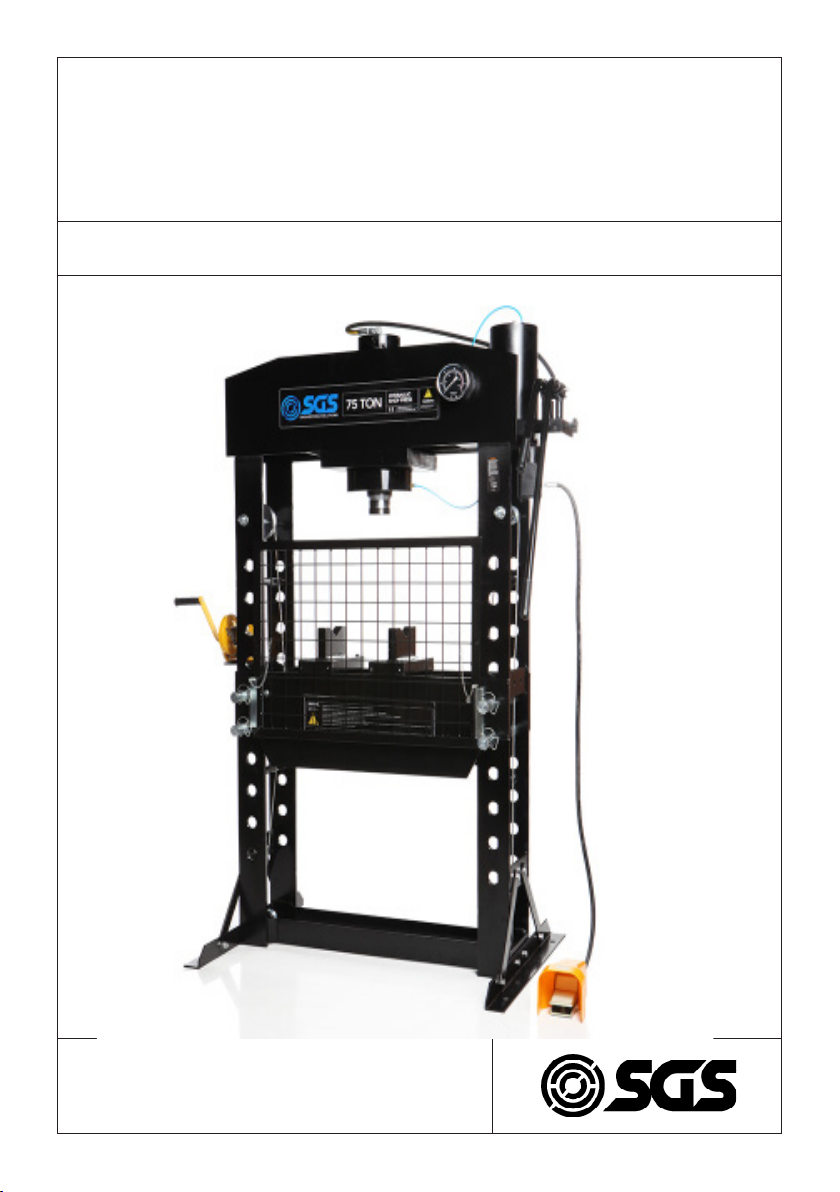
• Workshop and industrial hydraulic presses
• Hydraulic cylinders, pumps, tools & equipment

EC Declaration of Conformity
This is an important document and should be retained
MANUFACTURER’S NAME:
TYPE OF EQUIPMENT:
PART NUMBER:
I, the undersigned, hereby declare that the equipment specied above
conforms to the above European Communities Directive(s) and
Standard(s).
PLACE:
DATE: (Signature)
Robert Wyatt
Company Secretary
Derby, UK
24th JUNE 2017
SGS Engineering (UK) Ltd
West Side Park
Raynesway
Derby, DE21 7AZ
Hydraulic Press
SHHP75
2006/42/EC Machinery Directive
EN ISO 12100-1:2003 +A1:2009
EN ISO 12100-2:2003 + A1:2009
APPLICATION OF EC COUNCIL DIRECTIVES / STANDARD:
Table of contents
Other SGS Power Tools manuals
Popular Power Tools manuals by other brands

Worx
Worx contour WX461 Original instructions

Magna-Matic
Magna-Matic MAG-8200 Series Original instructions

DeWalt
DeWalt XR LI-ION DCS391NT Original instructions

KRAFTWERK
KRAFTWERK CORDLESS IMPACT user manual

Cornwell Tools
Cornwell Tools AT-4000SD operating instructions

STEINEL PROFESSIONAL
STEINEL PROFESSIONAL HG2220E Information