SGS SSB400 User manual

FOR YOUR SAFETY
PLEASE READ THESE INSTRUCTIONS CAREFULLY
AND RETAIN THEM FOR FUTURE USE.
OWNER’S MANUAL
SSB400
SANDBLASTING CABINET
NoNoNo
PAGE 3
PAGE 2
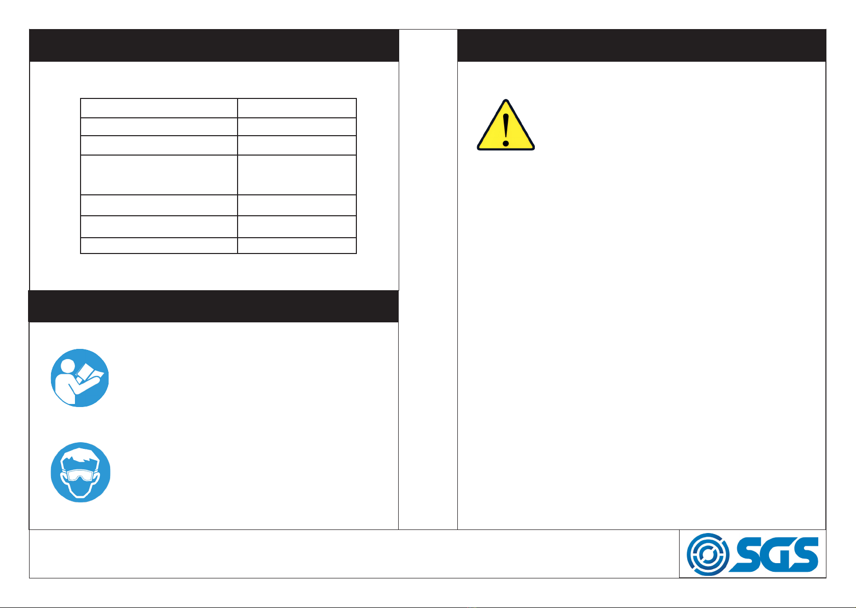
SPECIFICATION
MODEL No SSB400
MAX WORK PRESSURE 125 PSI / 8.6 BAR
WEIGHT 160kg
LENGTH
WIDTH
HEIGHT
1240mm
1330mm
1770mm
MOTOR 120V, 60Hz, 1100W
AIR CONSUMPTION 680L/min
AIR REQUIREMENT 24 CFM @ 125PSI
WARNING
Read and understand instructions before use.
Always wear eye/face and hand protection.
WARNING
Do not use any silica based abrasives with this cabinet.
Silica based abrasives have been linked to severe res-
piratory disease. Always use recommended abrasives.
Abrasives used in this unit may be covered by COSHH.
• All hoses sould be rated at least 125 PSI.
• Supplied air should be dry and clean from oil and other contaminants.
• Before operating the cabinet check seals on the doors, and make sure
dust collection system is running.
• This tank is NOT suitable for paint thinners, gun wash, or air drying.
• DO NOT operate the cleaning tank when you are tired, under the
influence of alcohol, drugs, or intoxication.
• When not in use switch the cleaning tank off and remove plug from
power supply.
• DO NOT operate the cleaning tank if any parts are missing or
damaged. Use original parts and do not sybstitute or modify original
supplied items.
WWW.SGS-ENGINEERING.COM

PAGE 5
PAGE 4
ELECTRICAL CONNECTIONS
WARNING! READ THESE ELECTRICAL SAFETY IN-
STRUCTIONS THOROUGHLY BEFORE CONNECTING
THE PRODUCT TO THE MAINS SUPPLY.
Before switching the product on, make sure that the voltage of your elec-
tricity supply is the same as that indicated on the rating plate. This product
is designed to operate on 230VAC 50Hz. Connecting it to any other power
source may cause damage.
This product may be fitted with a non-rewireable plug. If it is necessary to
change the fuse in the plug, the fuse cover must be refitted. If the fuse
cover becomes lost or damaged, the plug must not be used until a suitable
replacement is obtained.
If the plug has to be changed because it is not suitable for your socket, or
due to damage, it should be cut off and a replacement fitted, following the
wiring instructions shown below. The old plug must be disposed of safely,
as insertion into a mains socket could cause an electrical hazard.
We strongly recommend that this machine is connected to the mains sup-
ply via a Residual Current Device (RCD). If in doubt, consult a qualified
electrician. DO NOT attempt repairs yourself.
Plug must be BS1363/A
approved
Always fit a 3amp fuse
Live
(Brown)
Earth
(Green & Yellow)
Blue
(Neutral)
1. Upend the base and use M8x20 hex bolts to attach leg A and leg B,
then mount on the bracket.
2. Use M8x20 hex bolt and spring washers to attach the leg reinforcement
bars.
3. Place the assembled parts upright, then put the funnel in the centre.
Please note: The front of the funnel should be facing leg B.
4. Place the upper cabinet on the assembled stand. The front of upper
cabinet should be facing leg B.
5. Open the double folded door and attach the upper cabinet, big funnel &
bracket together with 22pcs M6x16 round head screws and faced washers.
6. Use 4pcs M6x12 bolts & M6 flange nuts to mount the dust collector at
the backboard of the upper cabinet. Plug the dust collector plug into the
switch box through the slot on the right of the upper cabinet.
ASSEMBLY
WWW.SGS-ENGINEERING.COM

PAGE 7
PAGE 6
ASSEMBLY
7. Mount pressure regulating valve on the leg B, and connect the orange
air hose to the side hole of funnel, then connect it to the sandblast gun.
8. Place the left / right grid in the upper cabinet.
9. Move the sandblaster to its final position by forklift, then remove the
reinforcing front leg.
PARTS DIAGRAM
WWW.SGS-ENGINEERING.COM

PAGE 9
PAGE 8
PARTS DIAGRAM PARTS LIST
No Description Part No No Description Part No
1 Upper cabinet 903848 35 Support pole of air springs 903882
2 Round head cross screws 903849 36 Plastic slot board of wire 903883
3 Suction sand hose 903850 37 Front door latch 903884
4 Left grid 903851 38 Latch seats 903885
5 Right grid 903852 39 Rack board 903886
6 Sealing tape 903853 40 Grips 903887
7 Big funnel 903854 41 Elements of big hoops 903888
8 Bracket 903855 42 Mounting ring of gloves 903889
9 M8x20 Bolt 900393 43 Glove seats 903890
10 Leg B 903857 44 Gloves 903891
11 Permanent seat of pneumatic device 903858 45 Sand board 903892
12 Pressure gauge 903859 46 Front opening door 903893
12 Pressure regulating valve 903860 47 Cap of nozzle 903894
13 Assembled latches 903861 48 Nozzle 903895
14 Welded cover board for falling sand 903862 49 “O” seal ring 903896
15 Pneumatic device of foot pedal 903863 50 Gun body 903897
16 Leg reinforces 1 903864 51 Sheath of air jet pipe 903898
17 Leg reinforces 2 903865 52 Lock nut 903899
18 Legs A 903866 53 Air jet pipe 903900
19 Dust collector 903867 54 Straight-pass connector 903901
20 M6x32 round head screws 903856 55 Conversion connector 903902
21 Bracket of viewing window 903868 56 Air hose 903903
22 Glass board of viewing window 903869 57 Quick fitting 903904
23 Glass of viewing window 903870 58 Clamps 903905
24 PE film of viewing window 903871 59 1/2” Sand hose 903906
25 Sealing tape of viewing window 903872 60 Switches 903907
26 Rubber seal strip of front opening doorframe 903873 61 Power cord of daylight lamp 903908
27 Bracket of top light 903874 62 wire clips 903909
28 Seat of fluorescent lamp/ lamps 4pcs 903875 63 Socket 903910
29 Glass of light window 903876 64 Cover of E-box 903911
30 PE film of light window 903877 65 Self tapping screws 903912
31 Rubber seal strip of light window 903878 66 Fuse seat 903913
32 sand boards 903879 67 Power cord 903914
33 Main body of upper cabinet 903880 68 Body of E-box 903915
34 Main support poles 903881
WWW.SGS-ENGINEERING.COM

OPERATING AND MAINTAINING
1. All parts processed must be free of oil, grease and moisture. Make sure
parts are dry before putting into the cabinet for cleaning.
2. Set air pressure to 80 psi. For light gauge steel, aluminum, and other
more delicate parts, start at lower pressure and gradually increase the
pressure until the desired finish is achieved.
Warning: Do not connect to high pressure bottled gas.
3. Direct gun at parts at 45-60 degree angle with ricochet towards the back
of the cabinet. Hold gun approximately 6 inches form parts being blasted.
Warning: Gun must always be pointed away from the operator and towards
items being processed. Never blast with any of the cabinet doors open.
4. Media should be of good quality and dry. Moisture will cause the media
not to flow and will clog the metering valve and hopper.
5. After 10-12 hours of blasting time, the nozzle should be checked. If it
shows uneven wear it should be turned 1/4 turn every 10 hours of use.
6. Replace nozzle if it’s measured 1/16 over its original size or if it shows
uneven wear. Adjust as needed for different media and conditions.
A properly working gun will pull 15-17 inches of mercury on manometer.
7. Clean dust from dust collector and clean filter as needed.
8. Air line should be more than 8mm (0.3”). All hoses should be rated for
125 psi (8.6 bar). An isolation valve should be installed.
9. Electric extension cords should be three wire grounded (wire size can
not be smaller than 3x1.5mm2 ).
10. Before starting inspect fittings and hoses for damage and water.
EC Declaration of Conformity
This is an important document and should be retained
MANUFACTURER’S NAME:
TYPE OF EQUIPMENT:
PART NUMBER:
I, the undersigned, hereby declare that the equipment specied above
conforms to the above European Communities Directive(s) and
Standard(s).
PLACE:
DATE: (Signature)
Robert Wyatt
Company Secretary
Derby, UK
24th NOV 2018
SGS Engineering (UK) Ltd
SGS Engineering (UK) Ltd
West Side Park
Raynesway
Derby, DE21 7AZ
SHOT BLASTER CABINET
SSB400
2014/35/EU Low Voltage Directive
2014/30/EU EMC Directive
2012/19/EU WEEE Directive
2011/65/EU RoHS Directive
APPLICATION OF EC COUNCIL DIRECTIVES / STANDARD:
FOR YOUR SAFETY
PLEASE READ THESE INSTRUCTIONS CAREFULLY
AND RETAIN THEM FOR FUTURE USE.
Table of contents
Other SGS Power Tools manuals


