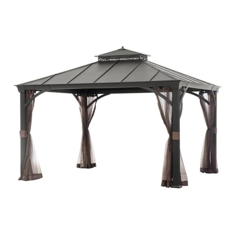
Shade N' Shelters Granite Peak GP/GAZ1214 User manual

1of24
Owner’s Manual
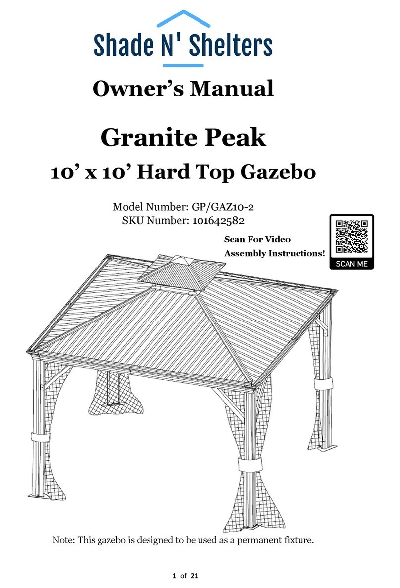
Granite Peak
12’ x 14’ Hard Top Gazebo
Model Number: GP/GAZ1214
Note: This gazebo is designed to be used as a permanent fixture.
Scan For Video
Assembly Instructions!

2of24
Parts List
Granite Peak 12’ x 14’ Hard Top Gazebo
Letter
Illustration
Description
Qty.
A
Corner Post
4
B
Corner Post Base Plate
4
C1
Short Lintel
2
C2
Short Lintel
2
D1
Long Lintel
2
D2
Long Lintel
2
E
Lintel Corner Support Bar
8
F
Lintel Bracket
6
G1
Lintel Connector – Small
2
G2
Lintel Connector - Large
4
H
Main Roof Corner Support
4

3of24
Letter
Illustration
Description
Qty.
I
Main Roof Vertical Center Support
6
J1
Main Roof Center Frame – Short
Connector
2
J2
Main Roof Center Frame - Long Connector
2
K1
Roof Vent - Corner Supports
4
K2
Roof Vent - Center Support
1
K3
Roof Vent Hook
1
L
Roof Vent - Top Trim
1
M
Main Roof – Lower Horizontal Support
8
N
Main Roof – Upper Horizontal Support
8
O
Main Roof – Center Horizontal Support
4
O1
Main Roof Connector – Corner
8
O2
Main Roof Connector – Center
12

4of24
Letter
Illustration
Description
Qty.
P1
Roof Vent Frame – Short Sides
2
P2
Roof Vent Frame – Left Sides
2
Q1
Main Roof Corner Trim
4
Q2
Roof Vent Corner Trim
4
Q4
Main Roof Center Frame Trim -
Long Sides
6
R1
Roof Vent Side Trim - Short Sides
2
R2
Roof Vent Side Trim - Long Sides
2
S1
Lintel Cover - Corner
4
S2
Lintel Cover - Center
4
T1
Main Roof Panel
4
T2
Main Roof Panel
4
T3
Main Roof Panel
4

5of24
Letter
Illustration
Description
Qty.
T4
Main Roof Panel
4
T5
Main Roof Panel
4
T6
Main Roof Panel
4
T7
Main Roof Panel
2
U1
Roof Vent Panel - Short Side
2
U2
Roof Vent Panel - Long Side (Left)
2
U3
Roof Vent Panel - Long Side (Right)
2
V
Mosquito Netting
4
AA
M6 x 15mm Bolt with Steel Washer
218
BB
M8 x 15mm Bolt with Steel Washer
48
CC
M6 x 15mm Bolt with Plastic Washer
12
DD
M6 x 15mm Bolt
16

6of24
Letter
Illustration
Description
Qty.
EE
M6 x 25mm Bolt with Plastic Washer
28
FF
M6 x 35mm Bolt with Plastic Washer
8
GG
M6 x 40mm Bolt with Plastic Washer
8
HH
M6 x 50mm Bolt with Plastic Washer
2
II
M6 x 55mm Bolt with Flat Washer & Nut
4
JJ
Mosquito Netting Hook
56
KK
Spacer
28
LL
Ground Stake
12
MM
M8 Allen Wrench
1
NN
M6 Hex Wrench
2

7of24
Assembly Instructions
Granite Peak 12’ x 14’ Hard Top Gazebo
Note: For video instructions please visit:
https://shadenshelters.com/12x14-granite-peak-gazebo
Important:
⚫Read all the instructions before assembly. Failure to do so may result in faulty assembly and
potential injury.
⚫Before assembling the product, remove all protective materials, hardware kit(s), and identify all
parts packed in the carton are present. (Note: If any part is missing or damaged, do not attempt to
assemble). Contact Shade N’ Shelters Customer Support. See page 24.
⚫Assemble on a stable level surface to avoid damage to gazebo and possible injury.
⚫Two people are required to assemble this product.
⚫Gazebo dimensions are measured from roof corner to roof corner.
WARNING: DO NOT TIGHTEN BOLTS UNTIL NOTED AFTER EACH STEP!
Step 1: Connect Corner Post Base Plate (B) to Corner Post (A) using Bolts (AA). Repeat for all Corner Posts
and Base Plates. Tighten all Bolts. See Figure 1.
Figure 1

8of24
Step 2A: Insert sixteen Mosquito Netting Hooks (JJ) into the channel of each Long Lintel (D2).
See Figure 2-1.
Note: The extra channel is for optional privacy curtain. Available at https://shadenshelters.com/
Step 2B: Attach Lintel Connector Large (G2) to Long Lintel (D2) using Bolts (BB). See Figure 2-2
Step 2C: Attach Long Lintel (D1) to Lintel Connector (G2) using Bolts (BB). Attach outside Lintel Brackets
(F) to Long Lintel (D1 and D2) using Bolts (AA). Tighten all Bolts. Repeat Step 2A to 2C for
remaining Long Lintels (D1 and D2). See Figure 2-3.
Step 2D: Insert twelve Mosquito Netting Hooks (JJ) into the channel of each Short Lintel (C2).
See Figure 2-4.
Step 2E: Attach Lintel Connector Small (G1) to Short Lintel (C2) using Bolts (AA). See Figures 2-5.
Step 2F: Attach Short Lintel (C2) to Lintel Connector Large (G2) using Bolts (BB). Attach Short Lintel (C1)
to Lintel Connector (G2) using Bolts (BB). Note: Leave 1 Bolt Hole open on both Short Lintels (C1
and C2) for Step 2G. See Figure 2-5 and Figure 2-6.
Step 2G: Attach Lintel Bracket (F) to Short Lintels (C1 and C2) using Bolts (BB). Tighten all Bolts. See
Figure 2-6. Repeat Step 2D to 2G for remaining Short Lintels (C1 and C2).
Figure 2-1 Figure 2-2
Figure 2-3
Figure 2-4
Figure 2-5
Figure 2-6

9of24
Step 3A: Attach Corner Posts (A) to end of Long Lintels (D1 and D2) first with Bolts (AA) then with Bolts
(DD). Tighten all Bolts. See Figure 3-1.
Step 3B: Repeat for opposite side Long Lintels (D1 and D2) and Corner Posts (A). See Figure 3-2.
Figure 3-1
Figure 3-2

10 of24
Step 4A: Attach Corner Posts (A) to Short Lintel (C1 and C2) first with Bolts (AA) then with Bolts (DD).
Repeat for opposite side Short Lintels (C1 and C2). See Figure 4-1.
Step 4B: Attach Support Bars (E) to Lintels (C1 and D2) and Corner Post (A) with Bolts (AA).
See Figure 4-2.
Step 4C: Repeat for all Corner Posts and Lintels. Tighten all Bolts. See Figure 4-3.
Figure 4-1
Figure 4-2
Figure 4-3

11 of24
Step 5A: Attach Corner Lintel Cover (S1) to Long Lintel (D1) and Short Lintel (C2) with Bolts (AA). Repeat
for all corners. Tighten all Bolts. See Figure 5-1.
Step 5B: Attach Center Lintel Cover (S2) to Long Lintels (D1 and D2) and Short Lintels (C1 and C2).
Tighten all Bolts. See Figure 5-2.
Step 5C: Repeat for opposite sides. Tighten all Bolts. See Figure 5-3.
Figure 5-1 Figure 5-2
Figure 5-3
Figure 5-2
Figure 5-1

12 of24
Step 6A: Assemble the Main Roof Center Frame by inserting the Long Connector (J2) into the Short
Connector (J1) and attach with Bolts (AA). See Figure 6-1.
Step 6B: Repeat for opposite sides and ends. Tighten all Bolts. See Figure 6-2.
Figure 6-1
Figure 6-2

13 of24
Step 7A: Assemble the Main Roof Corner Supports (H) to the Short Connector (J1) on the Main Roof Center
Frame and then to the Corner Posts (A) using Bolts (AA). See Figure 7-1.
Note: You will need a second person to hold the Main Roof Center Frame while attaching the Main
Roof Corner Supports (H).
Step 7B: Repeat for all corners and Tighten all Bolts.
Note: Diagonal measurements from corner to corner must be within 5mm of the same distance.
See Figure 7-2.
Figure 7-1
Figure 7-2

14 of24
Step 7C: Attach the Main Roof Vertical Center Supports (I) to the Main Roof Center Frame (J1 and J2) and
the Lintel Brackets (F) using Bolts (AA). Hand Tighten Only. See Figure 7-3.
Step 7D: Repeat for each side. Tighten all Bolts. See Figure 7-4
Figure 7-3
Figure 7-4

15 of24
Step 8A: Assemble the Roof Vent Frame by attaching Roof Vent Corner Support (K1) to Roof Vent Center
Support (K2) using Bolts (II). See Figure 8-1.
Step 8B: Screw in Roof Vent Hook (K3) into Roof Vent Center Support (K2). See Figure 8-2.
Step 8C: Repeat for all corners. Tighten all Bolts. See Figure 8-3.
Figure 8-1 Figure 8-2
Figure 8-3

16 of24
Step 9A: Attach the sides of the Roof Vent Frame by connecting the Short Side (P1) and Long Side (P2) to
the Roof Vent Corner Support (K1) using Bolts (AA). See Figure 9-1.
Step 9B: Repeat for remaining Short Side (P1) and Long Side (P2). Tighten all Bolts.
Step 9C: Secure the Roof Vent Frame to the Main Roof Center Frame by inserting the Roof Vent Corner
Supports (K1) into the post on the Short Connector (J1) of the Main Roof Center Frame and attach
using Bolts (AA). See Figure 9-2.
Step 9D: Repeat for all corners. Tighten all Bolts. See Figure 9-3.
Note: This will take at least two people.
Figure 9-1 Figure 9-2
Figure 9-3

17 of24
Step 10A: Assemble Roof Vent Panels by placing Left Roof Vent Panel (U2) on the Roof Vent Frame then
placing the Right Roof Vent Panel (U3) on the Roof Vent Frame and secure to Long Side of the
Roof Vent Frame (P2) using Bolt (CC).
Note: The Right Roof Vent Panel (U3) must overlap the Left Roof Vent Panel (U2).
See Figure 10-1.
Step 10B: Secure the Roof Vent Panel (U1) to the Short Side of the Roof Vent Frame (P1) using Bolt (CC).
See Figure 10-2.
Figure 10-1
Figure 10-2

18 of24
Step 10C: Repeat for opposite long and short sides. Tighten all Bolts. See Figure 10-3.
Step 10D: Attach the Short Roof Vent Trim (R1) and Long Roof Vent Trim (R2) to the Sides of Roof Vent
Frame (P1 and P2) using Bolts (AA). Repeat for all sides. Tighten all Bolts. See Figure 10-4.
Figure 10-3
Figure 10-4

19 of24
Step 11A: Attach the Roof Vent Corner Trim (Q2) to the Roof Vent Corner Support (K1) using Bolts (FF).
See Figure 11-1.
Step 11B: Repeat for all corners. Tighten all Bolts. See Figure 11-2.
Step 11C: Attach the Roof Vent Top Trim (L) to the Roof Vent Center Support (K2) using Bolts (HH).
Tighten all Bolts. See Figure 11-3 and Figure 11-4.
Figure 11-1 Figure 11-3
Figure 11-4

20 of24
Step 12A: Attach the Main Roof Connectors (O1) to the Main Roof Corner Supports (H) using Bolts (AA).
See Figure 12-1.
Step 12B: Attach the Main Roof Connectors (O2) to the Main Roof Vertical Center Supports (I) using Bolts
(AA). See Figure 12-2.
Step 12C: Attach the Main Roof Horizontal Supports (M and N) to the Main Roof Connectors (O1) using
Bolts (AA). See Figure 12-3.
Step 12D: Attach the Main Roof Horizontal Supports (M, N and O) to the Main Roof Connectors (O2) using
Bolts (AA). See Figure 12-4.
Step 12E: Repeat for all sides. Tighten all Bolts. See Figure 12-5.
Figure 12-1 Figure 12-2
Figure 12-3 Figure 12-4
Figure 12-5
Table of contents
Other Shade N' Shelters Outdoor Furnishing manuals
Shade N' Shelters
Shade N' Shelters Granite Peak GP/GAZ10-2 User manual
Shade N' Shelters
Shade N' Shelters UMB-10-STD User manual
Shade N' Shelters
Shade N' Shelters GP/GAZ14-2 User manual
Shade N' Shelters
Shade N' Shelters Granite Peak GP/GAZ-1212 User manual
Shade N' Shelters
Shade N' Shelters SUM-GAZ-2 User manual
Shade N' Shelters
Shade N' Shelters Jordan JOR/PERG-2 User manual
Shade N' Shelters
Shade N' Shelters Lexington LEX/GAZ-2 User manual

Shade N' Shelters
Shade N' Shelters Belmont BEL/GAZ-2 User manual
Shade N' Shelters
Shade N' Shelters Chesterfield User manual
Shade N' Shelters
Shade N' Shelters Berken User manual

