Sharp FU-800-J User manual

ENGLISH
FU-800-J
AIR PURIFIER
OPERATION MANUAL
Floor type
R


ENGLISH
FEATURES
Plasmacluster Ion Control
Theunitcontrolstheratioofnegativeions
and positive ions depending on the con-
dition of the room.
•Clean Mode
Approximatelythesamenumbersofposi-
tive and negative ions are discharged.
This mode is effective for reducing some
airborne mold.
•Ion Control Mode
It is said that plenty of negative ions exist
innaturalsurroundingssuchaswaterfalls
or forests. In this mode, negative ions will
be released in an increased rate, in order
to bring the room air close to this natural
environment.
•AUTO Plasmacluster Ion Mode
The unit will switch between Clean Mode
and Ion Control Mode automatically de-
pending on the amount of pollution in the
air detected by Dust and Odour Sensor.
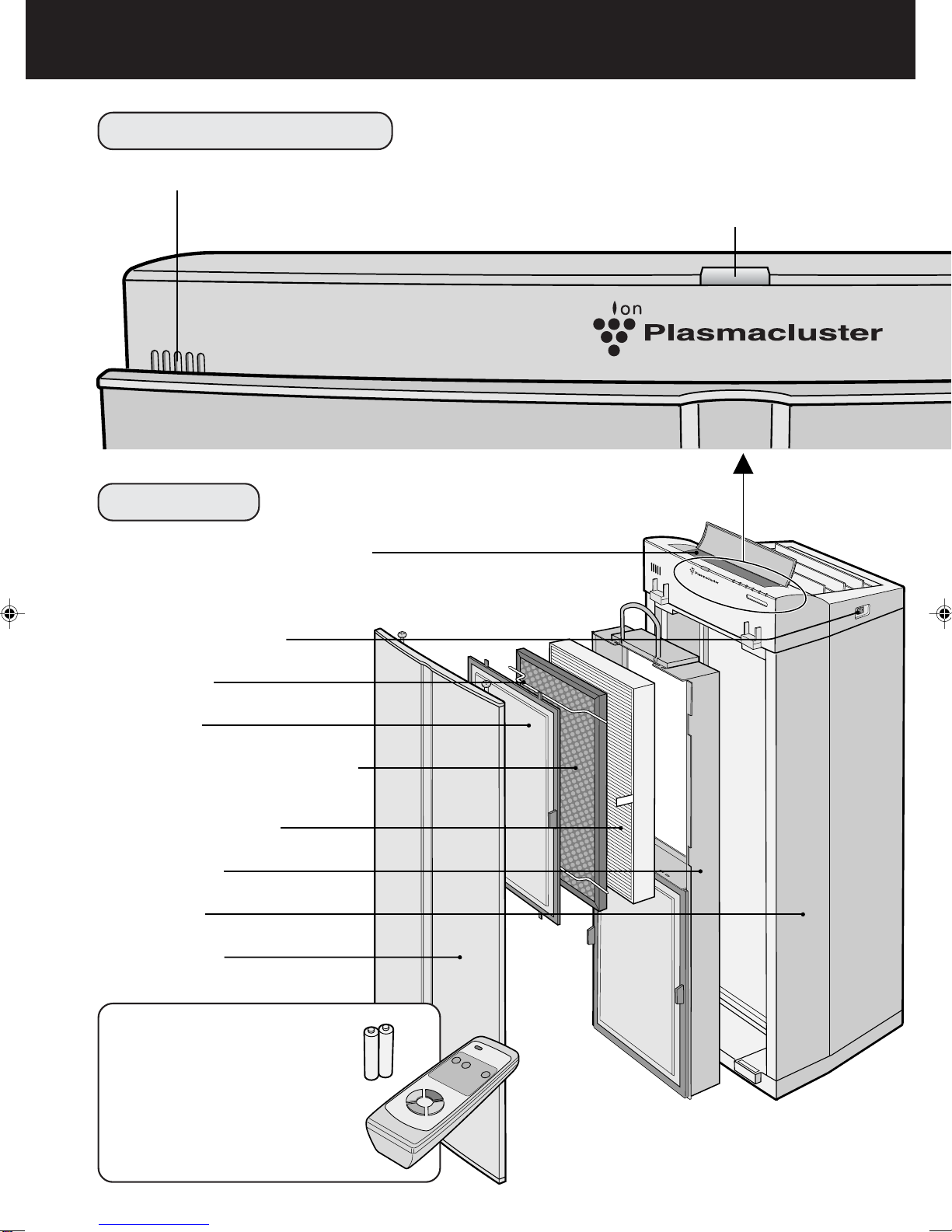
•Filters
1) Pre-Filter
It collects large particles.
2) Active Carbon Filter with microbial
control filters
Powerful deodorization by large parti-
cles of columnar charcoal.
3) HEPA (High Efficiency
Particulate Air) Filter
High-efficiency particle collection in-
cluding pollen and dust.
CONTENTS
SAFETY PRECAUTIONS ........................ E-2
•WARNING FOR INSTALLATION/
REMOVAL/REPAIR...................................... E-2
•CAUTIONS CONCERNING THE
USAGE OF THIS PRODUCT.......................E-3
•REMOTE CONTROL LIMITATIONS ............E-3
•FILTER GUIDELINES ..................................E-3
PART NAMES.......................................... E-4
•MAIN UNIT DISPLAY...................................E-4
• FRONT.........................................................E-4
• ACCESSORIES ...........................................E-4
• BACK ...........................................................E-5
•OPERATION PANEL....................................E-6
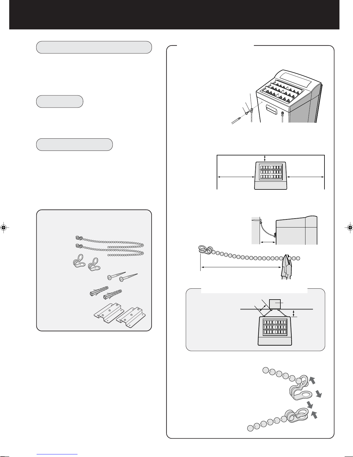
INSTALLATION ....................................... E-8
PREPARATION...................................... E-10
•FILTER INSTALLATION ............................ E-10
•ATTACHING THE FILTER,
FILTER FRAME, AND FRONT PANEL ......E-11
• SETTING UP THE CURRENT TIME ........ E-12
•INSERTING BATTERIES
IN THE REMOTE CONTROL ................... E-13
•REMOTE CONTROL USE........................ E-13
OPERATION ..........................................E-14
•MAIN UNIT OPERATION.......................... E-14
•REMOTE CONTROL OPERATION .......... E-16
CONVENIENT FUNCTIONS.................. E-17
•2-HOUR OFF TIMER ................................ E-17
•LOCK FUNCTION..................................... E-17
•SENSITIVITY SWITCH ............................. E-17
•PRESET TIMER........................................ E-18
•SWITCHING THE DISPLAY ..................... E-19
OPERATION GUIDE.............................. E-20
SPECIFICATIONS ................................. E-20
CARE AND MAINTENANCE................. E-21
•MAIN UNIT................................................ E-21
• PREPARATION......................................... E-21
•DUST SENSOR, ODOUR SENSOR......... E-21
•FILTER CLEANING................................... E-22
•SETTING THE FRONT PANEL ................ E-22
•FILTER REPLACEMENT GUIDELINES ... E-23
TROUBLE SHOOTING.......................... E-24
Thank you for purchasing the SHARP FU-800-
J.Pleaseread this manual carefully for the cor-
rect operation. Before using this product, be
sure to read the section: “Safety Precautions.”
After reading this manual, retain it in a conven-
ient location for future reference.
E-1
FOR UNDERSTANDING
THE PRODUCT
Some of the odour ingredients ab-
sorbed by the filters become sepa-
rated and are discharged through the
Air Outlet as odour.
Dependingon theusage environment,
this odour may become strong in sev-
eral months and The Air Outlet may
smell.
Inthis case,purchaseexchange filters
and replace the filters.
•HEPA Filter : PFIL-A059KKEZ
•
Active Carbon Filter
: FFIL-A006KKKZ
ENGLISH

•The appliance is not intended for use by young children or infirm persons without supervi-
sion.
•Young children should be supervised to ensure that they do not play with the appliance.
•Do not use the unit if the Power Cord or Plug is damaged or the connection to the wall outlet
is loose.
Electrical shock, short circuit and/or fire may occur as a result.
•Do not damage, break, coat, forcefully bend, pull, twist, bundle, pinch or place heavy objects
on the power cord.
If the power cord is damaged, fire and/or electrical shock may occur as a result.
•Use AC 220-240V only.
If AC 220-240V is not used, fire and/or electrical shock may occur as a result.
•Periodically remove dust from the Power Plug.
Accumulated dust on the Power Plug may cause bad insulation from humidity, etc. Fire and/or elec-
trical shock may occur as a result.
•When cleaning the unit, be sure to remove the Power Plug from the wall outlet.
In addition, never handle the Power Plug with wet hands.
Electrical shock and/or bodily injury may occur as a result.
• Do not use the unit where there are oil ingredients such as cooking oil, in the air.
Cracking of the unit surface may occur as a result.
•Do not wipe the unit with benzene or paint thinner.Also, do not spray insecticides on the unit.
Cracking, electrical shock and/or fire may occur as a result.
•Do not operate the unit when using indoor smoke-generating insecticides.
Chemical ingredients may accumulate within the unit and then discharge from theAir Outlet when the
unit operates. Discharge of such chemicals may be unhealthy to your body.
•Do not allow the unit to intake flammable gases, sparks from lit cigarettes, incense.
The unit may ignite as a result.
• Do not use the unit where it is humid, such as in a bathroom, or where the unit may get wet.
Electrical shock and/or malfunction may occur as a result.
• Do not insert fingers or foreign objects into the intake or Air Outlet.
Electrical shock and/or malfunction may occur as a result.
•When removing the Power Plug, always hold the plug and never pull the cord.
Electrical shock an/or fire from short circuit may occur as a result.
•Ventilate when using the unit along with a heating appliance.
The unit can not remove carbon monoxide, so carbon monoxide poisoning may occur as a result by
a heating appliance.
•Remove the power plug when not using the unit for a long time.
Electrical shock from bad insulation and/or fire from short circuit may occur as a result.
•If the Power cord is damaged, it must be replaced by the manufacturer or its service agent or
similarly qualified person in order to avoid a hazard.
•The batteries must be removed from the appliance before it is scrapped and that they are
disposed of safely.
WARNING FOR INSTALLATION / REMOVAL / REPAIR
•Do not attempt install/remove/repair the unit by yourself. Incorrect work will cause electric shock, fire
etc. Consult your dealer or other qualified service personnel for the installation/removal/repair of the
unit.
•The appliance must be positioned so that the power plug is accessible.
SAFETY PRECAUTIONS
E-2

ENGLISH
CAUTIONS CONCERNING THE USAGE OF THIS PRODUCT
•Do not block the intake and Air Outlet.
•Do not use the unit near or on hot objects, such as a stove. Also, do not use the unit where it
may come into contact with steam.
•Do not use the unit on its side.
Deformation, malfunction and/or overheating of the motor may occur as a result.
•Do not install when there is generation of lampblack, such as in a kitchen.
•Do not use detergent when cleaning the unit.
The unit surface may become damaged or cracked.
In addition, the Sensors may malfunction as a result.
•Do not operate the unit without the filter.
It will have no purification effect. In addition, it becomes the cause of the trouble.
•Do not wash and reuse filters.
They do not have effect, and it becomes an electric shock and the cause of the trouble.
•When transporting the unit, always hold the handle on the back of the unit.
Holding the Front Panel when carrying may cause it to detach, thus dropping the unit and resulting in
bodily injury.
REMOTE CONTROL LIMITATIONS
DO NOT USE THE REMOTE CONTROL IN THE FOLLOWING LOCATIONS
•Any location where there is an inverter lighting equipment or a electronic spontaneous light-
ing equipment
The Remote Control may become inoperative. In this case, move away from such lighting equipment
or change direction.
•Location exposed to direct sunlight
The unit may not receive signals from the Remote Control.
The unit may not respond to the signals of the Remote Control if the ends of fluorescent lighting
become black or lights flicker due to the depletion of service life; however, this is not a malfunction of
the Remote Control or the Main unit. In this case, replace the lighting with new fluorescent tubes.
INSTALLATION GUIDELINES
•Leave at least 2m of space from equipments which involved electric wave such as televi-
sions, radios or wave clocks.
Electrical interference may occur if not.
•Leave at least 60cm of space from the side wall.
The motor may overheat, causing malfunction if not.
•Avoid a location where sensors are exposed to direct wind.
The unit may not operate properly.
•Avoid a location where curtains, etc., come into contact with the intake or Air Outlet.
Curtains, etc., may become dirty or malfunction may occur as a result.
EFFECTIVE OPERATION
•Place on a stable surface with sufficient air circulation.
FILTER GUIDELINES
•Do not wash and reuse HEPA Filter and Active Carbon Filter. It does not work effectively, and may
become a cause of electric shock and trouble.
•The wall behind the Air Outlet may become dirty as time passes. When using the unit for extensive
period in the same location, use a vinyl sheet, etc., to prevent the wall from becoming dirty. In addi-
tion, periodically clean the wall, etc.
E-3

E-4
PART NAMES
MAIN UNIT DISPLAY
Dust Sensor Plasmacluster Lamp
Press the Plasmacluster Select Button on the Main unit
or Remote Control to select Plasmacluster Ion Mode.
FRONT
ACCESSORIES
Battery (R6(AA) battery X 2)
Remote Control (1 unit)
Phillips screwdriver (1 unit)
Anti-toppling kit (1 unit)
Metal fittings (2 units)
Operation Manual
Operation Panel (refer to E-6. )
Main Power Switch
Filter Fixes
Pre-Filters
Active Carbon Filters
(Front:black)
Microbial Control Filters
(Back:white)
HEPA Filters (white)
Filter Frame
Main unit
Front Panel

ENGLISH
E-5
Fan Level Lamps
2-hour OFF Timer Display Lamp
set pressing the 2-hour OFF Timer But-
ton on the Main unit or Remote Control.
Power Lamp
Lights up in red when the Main Power
Switch is turned on. Lights up in green
when the ON/OFF Button is pressed or
the Remote Control is used to start op-
eration.
Odour Sensor
Remote Control Receiver
BACK How to open the cover
(Press)
Cover for the operation area
Movable Louvers
Left/right Louvers
Handle
Screws for attaching the anti-
topple chains
Power Cord
Casters
Air Outlet
Power Plug

E-6
PART NAMES
OPERATION PANEL
Lock Lamp PM Lamp
AM Lamp
Digital Display
OFF Timer Lamp
ON Timer Lamp
Current Time Lamp
LOCK Button
All other buttons along this
operationpanelaredisabled
when this LOCK Button is
pressed. (Refer to E-17)
-
Button
Reverses the time
during setting.
(Refer to E-12,18)
Sensor Sensitivity Select Switch
Switches sensor response between
‘High’, ‘Sensitivity Normal’, and ‘Low’.
(Refer to E-17)
SET Button
Sets up the current time
and the on/off timers.
(Refer to E-12,18)
+Button
Forwards the time
during setting.
(Refer to E-12,18)
CLOCK Button
Sets up the current
time and the on/off
timers.
(Refer to E-12,18)
Filter Reset
Press the LOCK Button and 2h OFF
Timer Button at the same time for
three seconds.
(Refer to E-23)

ENGLISH
E-7
me Lamp
2-hour OFF Timer Lamp
PRESET Lamp
Plasmacluster Select Lamp
PRESET Button
Sets up and cancels
the on/off timer for 24
hours.
(Refer to E-18)
Fan Level Select Button
Set fan level between ‘Silent’,
‘Medium’, ‘High’, and ‘Auto’.
(Refer to E-14,18)
ON/OFF Button
Used to turn the unit
on/off. (Refer to E-14)
2-hour OFF Timer Button
Setsupand cancels the on/
off timer for 2-hours off.
(Refer to E-17)
Plasmacluster Select Button
Switches between Plasmacluster
Ion Modes. (Refer to E-15)

INSTALLATION
E-8
NOTE
•The anti-toppling kit must be attached to en-
sure safety.
INSTRUCTIONS
•Where the back of the air purifier is closest to
the wall, a mark is likely to result after a while,
so it is recommended that a protective vinyl
sheet or suchlike be attached to the wall.
•Please select a strong site to install the sys-
tem, such as beside a stable pillar and sash
bar.
•Pleasecontact professionalsforinstallationon
weak partitions or concrete wall.
PREPARATION
1
Remove the two small screws from the
Main unit, and
reattach with the
two Chains
2
Decide on the installation position.
Please ensure a gap from the back, left and right
walls as indicated below.
3
Decide on an appropriate chain length,
and cut the Chain to the required length
using pliers or
suchlike.
IF THE PILLAR IS NARROW
Chain length
should be
decided to
enable setting
as shown in
the illustration.
4
Attach the Clasp to the Chain.
1
OpentheClasp,andin-
sert the last sphere on
the chain through the
hole.
2Slide the sphere to the
end, and close the
Clasp.
Clasp
Spring washer
Small screw
10 cm or more
60 cm or more 60 cm or more
10 cm or more
Cut the chain to the
appropriate length.
Required length Pillar
10 cm or
more
ANTI-TOPPLING KIT
Chains (with a clasp at one end)
(30cmX2)
Clasps
(X2)
Wood screws
(30mmX2)
Fisher plugs
(X2)
Metal fittings
(X2)
WARNING FOR INSTALLATION
•Do not attempt install the unit by yourself. In-
correct work will cause electric shock, fire etc.
Consult your dealer or other qualified service
personnel for the installation of the unit.

ENGLISH
E-9
INSTALLATION AGAINST
WOODEN PANELLING
1
InserttheWoodscrew, and Screw
the Clasp together into the Panel.
NOTE
If the surface is plasterboard,
please install the system
againstastablepillartowhich
the plasterboard is attached.
1
Drill a hole on the wall.
Usea drill suited to thematerial of the wall,
and make a hole 5 mm in diameter and at
least 35 mm deep.
INSTRUCTION
Please ensure the wall, pillar, or sash bar
is at least 35 mm thick before installation.
2
Insert the Wood screw through
the Clasp of the Chain, and into
the mouth of the Fisher plug to a
depth that it is secure.
3
Insert the Fisher plug firmly into
the wall.
4
Screw in the Screw.
1
Clean the surface to be attached to.
Ensure that the surface is not greasy.
2
Attach the Metal fitting to the wall
using the double-side tapes on
the back.(2 pieces)
3
Insert the small screw enclosed
with the Metal fitting through the
Clasp of the Chain, and fasten it
up to the Metal
fitting.(2 pieces)
NOTES
•Please use a flat wall surface for such instal-
lation.
•Pleasecarefullyremove anyoil,moisture,and
dust from the wall surface before installation.
•Please attach the system tightly to the wall
by applying pressure.
•It takes a while for the adhesive on the tape
to set, so please do not exert undue loads on
the tape for a couple of hours.
Clasp
Small screw
Main unit
INSTALLATIONAGAINSTAN
ALC, CONCRETE, BRICK,
OR MORTAR WALL
Wood screw
Clasp
Fisher plug
Adjustthe foottoensure
stability.
Peel off the
cover sheets.
IN THE EVENT THAT THE
SCREWS CANNOT BE APPLIED
DIRECTLY TO A RETAINING WALL
20mm
SETTINGUPTHEUNITINAN
APPROPRIATE POSITION
Adjust the foot to ensure stability.
NOTE
•Please ensure the Chain has enough slack
to prevent it being fully extended or pulled-
out when the unit is set up.
Front Panel
ø5mm
35mm

Be sure to remove the power plug from the wall outlet.
E-10
PREPARATION •Be sure to remove the Power Plug from the wall outlet.
Handle
Pre-Filter
Tabs (X4)
Filter fixers
FILTER INSTALLATION
CAUTIONS
•IfyoupushtheFrontPanel,
theMainunitwillbebroken.
•Do not loosen the screws
whichholdtheFanGuards.
To maintain the quality of the filters, they
are placed in the Main unit within plastic
bags. Be sure to remove the filters from
the plastic bags before using the unit.
1
Filter Removal
1
Confirm to remove the Power Plug
and press the Main Power Switch at
the front side.
2
Extractthe handles at the topand bot-
tom of the Filter Frame, pull them out,
and remove the Filter Frame from the
Main unit.
NOTE
Two filters (top and bottom) are attached to the
FilterFrame. Afterremoval, lay the Filter Frame
flatwiththehandlesfacing upwards, andreplace
the filters.
3
Unhook the four tabs on the Pre-Fil-
ter,and remove the FilterFixers. (Two
each top and bottom)
4
ExtracttheActiveCarbon Filter (black
(back: white)) and HEPAFilter (white).
(One each top and bottom)
5
Remove the Active Carbon Filters
(black,white) and HEPAFilter from the
plastic bags.
Press
Deodorizing Filter (Front: black)
MicrobialControl Filter(Back: white)
HEPA Filter
Filter Frame
Fan Guards

ENGLISH
E-11
outlet.
1
Filter Installation
1
After the HEPA Filters are re-
movedfrom the plastic bag, place
it within the Filter Frame with the
“FRONT” sign facing up.
(See the diagram to the right.)
Ensurethatthefilters areinstalledcorrectly.
Do not install the filters backwards or the
unit will not operate properly.
2
After removing theActive Carbon
Filters from the plastic bag, and
place it over the HEPA Filter with
the black side facing up. (One
each top and bottom)
Attach it with the ‘removal tags’
protruding from the Filter
Frame.
3
Insert the Filter Fixers into their
sockets. (Two each top and bot-
tom)
4
Insert the four tabs on the Pre-
Filter into the Square Notches in
the Filter Frame. (Two each top
and bottom)
5
Fill in the usage start date on the
Date Label, which can be found
on upper of the Main unit.
Use the date as a guide for your filter re-
placement period.
6
Holding the Filter Frame by its
handle, secure it to the Main unit.
Recess both the top and bottom handles
into the Main unit.
7
Insertthe two Protruding Catches
located on the back of the Front
Panel into their housings on the
Main unit, and affix the Front
Panel to the Main unit using the
Top Screws (one each left and
right).
HEPA Filter (white)
Active Carbon Filter (Front: black)
Microbial Control Filter (Back: white)
Filter Frame
Removal tag Sockets
Removal
tags
Filter Fixers
Tabs (X4)
Back of the front panel
ATTACHING THE FILTER, FILTER FRAME, AND FRONT PANEL
FRONT
Square
Notches
Housings
Protruding Catches
Phillips screws
Front Panel
Date Label

PREPARATION
SETTING UP THE CURRENT TIME
E-12
1
Insert the Power Plug into the outlet.
2
Turn on the Main Power Switch.
The Power Lamp is lit red and the digital dis-
play blinks.
NOTE
The current time must be set up while the unit
is non-operational. It cannot be set up during
operation.
3
Press the SET Button.
The Colon in the middle of the Digital Display stops blinking, and the indicated cur-
rent time blinks.
4
Press the
+
Button or
-
Button.
Set up the current time while observing the Digital Display.
•Thetime advances by one minute witheachpress of the +Button, and goesback
by one minute with each press of the
-
Button.
•This process will increase in speed if the relevant button is pressed continuously.
Pressthe +Button or
-
Button while the colonis not blinking (about60 seconds).
If the colon starts blinking again, repeat this operation from Step 3.
•The a.m. and p.m. settings must also be set correctly.
5
Press the SET Button.
The colon in the middle of the Digital Display starts blinking, and the clock starts
running.
Colon

ENGLISH
INSERTING BATTERIES IN THE REMOTE CONTROL
1
Remove the Back Cover
Press and slide the back cover to re-
move.
2
Insert batteries
Insert batteries with and as
shown below.
3
Close the Back Cover
REMOTE CONTROL USE
•OperatewiththeRemoteControlfacingtheMain
unit (Receiver).
•The signal range is about 7m (front).
•Makesurethereare no objects blocking the path
of the signal.
•Abeep sound will be heard from the Main unit
when a signal is received.
NOTE
•Avoiddropping or damaging on the Remote Con-
trol. In addition, be sure the Remote Control
avoids moisture or place in direct sunlight or near
an electric heater, etc., otherwise a malfunction
may occur.
E-13
Battery Information
•The battery life is about 1 year.
•Replace the batteries when the Remote Control becomes inoperative.
•Incorrect usage of the batteries may cause battery fluid leakage and/or
damage. Take care of the following when handling:
•When replacing the batteries, replace both batteries with new ones of
the same type. (Use 2 R6(AA) manganese batteries.)
•When not using the unit or Remote Control for an extended period,
remove the batteries. (This prevents malfunction of the Remote Con-
trol from battery fluid leakage.)
*The batteries of the accessory are for initial use only and may be de-
pleted within 1 year.
Receiver
Transmitter

E-14
OPERATION
MAIN UNIT OPERATION
Plasmacluster Lamp
1
Press the Main
Power Switch.
The Power Lamp is lit red.
2
Press the ON/OFF
Button
The Power Lamp is lit
green, and automatic op-
eration or operation at the
preset flow rate starts.
The fan level is switched as follows every time
the Fan Level Select Button is pressed.
AUTO
Silent
Medium
High
Thefanlevelisautomaticallyswitched
between the five levels depending on
the amount of impurities in the air. The
sensors detect the impurities for effi-
cient air purification.
Theunitwilloperatequietlyusingmini-
mal air intake.
Operateson the Medium fan level set-
ting.
OperatesontheHigh fan level setting.
1
OPERATION
2
FAN LEVEL SET UP

ENGLISH
E-15
Main Power Switch
It is on the right side of main unit.
Power Lamp
The Plasmacluster Ion Mode is switched as follows every time the
Plasmacluster Select Button is pressed.
Auto
Clean
Ion Control
Off
The unit will switch between Clean Mode and Ion Control Mode
automatically depending on the amount of impurities in the air de-
tected by the dust and odour sensors. Clean Mode operation will
operation for about 1 minute when the Auto function is selected.
The unit will constantly operate in Clean Mode. Clean Mode is
effectiveforreducingsomeairbornemold.(Plasmacluster Lamp is
blue)
The unit will constantly operate in Ion Control Mode. Ion balance
is maintained in the room by increasing the ration of negative ions.
(The Plasmacluster Lamp is green)
The generation of ions will cease and the Plasmacluster Lamp will
go out.
1
2
3
3
SET UP THE PLASMACLUSTER ION MODE

Plasmacluster
AUTO
OFF
2h OFF
E-16
OPERATION
REMOTE CONTROL OPERATION
•BeforeusingtheRemote Control,turntheMainPower Switch
on.
•When you press the POWER ON/OFF Button, a short beep
will sound and operation will start. It automatically goes to
the last operation mode.
•Tostopoperation,press the POWER ON/OFF Button again.
A long beep will sound and operation will stop.
PlasmaclusterIon Mode Selections
AUTO Plasmacluster Ion
When pressed the unit will switch between
Clean Mode and Ion Control Mode automati-
cally depending on the amount of impurities in
the air detected by the dust and odour sen-
sors.
Clean Mode operation will operate for about 1
minute when theAUTO function is selected.
Ion Control
The unit will constantly operate in Ion Control
Mode. Ion balance is maintained in the room
by increasing the ratio of negative ions.
(Plasmacluster Lamp is green)
Clean
When pressed the unit will con-
stantly operate in Clean Mode.
Clean Mode is effective for reduc-
ing some airborne mold.
(Plasmacluster Lamp is blue)
OFF
The generation of ions will cease
andthePlasmaclusterLampwill go
out.
If the room smells especially moldy, operate the unit in Clean Mode.
Operations available
with Remote Control
•
AUTO
•
MANUAL
•2-hour OFF Timer
Plasmacluster Ion Mode Selections
•
AUTO Plasmacluster Ion Mode
•Clean Mode
•Ion Control Mode
•
OFF
POWER ON/OFF Button
A short beep will signal that
theunitisonandalongbeep
means that the unit is off.
AUTO(FanLevel)Button
The fan level switches auto-
matically depending on the
amountofimpuritiesintheair.
MANUAL (Fan Level) But-
ton
Thefanlevelcan be switched
between Silent, Medium and
High.
Transmitter
2-hour OFF Timer Button
Pressing this button sets the 2-
hour OFF Timer. Press it again
to cancel the setting.

ENGLISH
CONVENIENT FUNCTIONS
E-17
2-HOUR OFF TIMER
Use this function to stop operation automatically after two hours.
1
Press the 2-hour OFF Timer Button during operation.
•A‘beep’ sound indicates that the 2-hour OFFTimer has been turned
on. Theunitwillturnoffabouttwohoursafter the buttonwaspressed.
Deactivating 2-hour OFF Timer
1
Press 2-hour OFF Timer Button
•A‘beep’ sound indicates that the 2-hour OFFTimer has been turned
off. The 2-hour OFF Timer is then deactivated
NOTE
If the PRESET Timer has been activated, it will then be deactivated and the 2-hour OFF
Timer takes priority.
SENSITIVITY SWITCH
The sensitivity of the Odour Sensor and the Dust Sensor can be adjusted. The
factory setting is Normal, so please switch it in accordance with the status of
the room environment.
NOTE
•It can be switched regardless of whether
the Main unit is locked or not.
LOCK FUNCTION
Use the LOCK Button to disable all the other operating buttons on the Main
unit.
1
Press the LOCK Button for one second.
•The Lock Lamp is lit. All displays on the operation panel are turned
off except the 2-hour OFF Timer Lamp and the PRESET Lamp.
How to unlock
1
Press the LOCK Button for about three seconds.
• The Lock Lamp is turned off, and the lock setting is deactivated.
NOTES
•Whilethe lock function is activated, all functionsexcept the Main Power Switch and Sensor
sensitivity Select Switch and Lock Button are disabled. The Operation Lamps are on in
accordance with the operational status.
•Operation is possible using the Remote Control.
2h OFF
2h OFF

CONVENIENT FUNCTIONS
E-18
PRESET TIMER
This function repeats the On and Off operations at the same time every day.
Up to three pairs of on and off times can be set.
If a pair of on and off times is set, the PRESET Timer function can be activated.
NOTES •Please set the timer after confirming that the current time setting is correct.
•The timer cannot be set until the clock is set.
•The preset timer function does not work until both on time and off time are
set.
•Please set the PRESET Timer while the unit is stopped. Setup is not possi-
ble while it is in operation.
1
Setting up the ON Time.
1
Press the CLOCK Button, and turn on the ON Timer Lamp.
2
Press the SET Button.
•The ON Timer Lamp blinks and the ON Timer set-up mode is acti-
vated.
3
Set the ON Time using the +and
-
Buttons.
4
Set the operating mode using the Plasmacluster Select Button and
Fan Level Select Button.
5
Press the SET Button.
• The ON Timer Lamp lights up indicating that set-up is complete.
2
Setting up the OFF Time.
1
Press the CLOCK Button, and turn on the OFF Timer Lamp.
2
Press the SET Button.
•The OFF Timer Lamp blinks and the OFF Timer set-up mode is
activated.
3
Set the OFF Time using the +and
-
Buttons.
4
Press the SET Button.
•The OFF Timer Lamp lights up indicating that set-up is complete.
NOTE
PRESET
PRESET
Automatically confirmed if about 60 seconds pass without the SET Button
being pressed. About eight seconds after the OFF Timer lamp turns off, it
automatically returns to the current time.
3
Setting up the PRESET Time.
Once the on and off times are set, they must be activated by pressing the PRESET Button
.
1
Press the PRESET Button while the unit is stopped.
•The Preset Lamp turns on indicating that the Preset Timer is set up.
Deactivating the Preset Timer.
1
Press the PRESET Button.
• The PRESET Lamp turns off indicating that the PRESET Timer is cancelled.
NOTES
•When the Main Power Switch is turned off, the PRESET Timer is cancelled. Even if the Main
Power Switch is turned on again, the status remains cancelled. However, the times that have
been set are still memorized.
•Three pairs of ON and OFF Times can be set, but in the event of any duplication, is shown on
the Digital Display, and set-up is not possible.
Table of contents
Other Sharp Air Cleaner manuals

Sharp
Sharp Plasmacluster FU-W25AW User manual

Sharp
Sharp KC-850EK User manual

Sharp
Sharp FP-H50A User manual

Sharp
Sharp FU-W43E User manual

Sharp
Sharp KC-A60TA User manual

Sharp
Sharp UA-PN1E User manual

Sharp
Sharp UA-PN1U User manual

Sharp
Sharp FX-J80J-W User manual

Sharp
Sharp IZCA10EKW Parts list manual

Sharp
Sharp FX-S120 User manual

Sharp
Sharp FZ-60SEF User manual

Sharp
Sharp Plasmacluster IG-GC2E User manual

Sharp
Sharp FX-S120B User manual

Sharp
Sharp IG-A10EU-W Manual

Sharp
Sharp IG-A20A? IG-A40A User manual

Sharp
Sharp IG-BC2E Plasmacluster Ion User manual

Sharp
Sharp FP-GM50E User manual

Sharp
Sharp HIGH-DENSITY 7000 User manual

Sharp
Sharp FZ-560HF User manual

Sharp
Sharp FP-E50TA User manual