Sharp er-3100 User manual

CODE: OOZER31001M.M
——

ENGLISH ......................Page 1
DEUTSCH. .....................Seite 59
FRAN~AIS. ....................Page 119
ESPANOL, .....,...............Pagina181

CONTENTS
Page
1. GENERAL *0*9**9***0*90***0******0*.*......................... 1
2. SUMMARY OF THE ER-3100 OPTIONS ●*.***....********,****,*...** 2
3. BEFORE INSTALLINGOPTIONS ...............●.*****.●**..*..●*.* 4
4.
5.
5.1
5.2
5.3
5.4
6.
6.1
6.2
6.3
6.4
7.
7.1
7.2
7.3
7.4
PRINTING OUT THE SRV-MODEAND PGM-MODE PROGWS .............
REMOVING THE TOP CABINET AND MAIN DRAWER .........**.......**
Removing the top cabinet .......●..***.*.*.*..**.*..*.*.●..*
Replacing the top cabinet ●.*..*.*..................●*.*.*.*
Removing the main drawer ...............●*.**..*●.*.*.......
Replacing the main drawer ..................................
Rs-232c INTERFACE (ER-31RS2)●**..*............*****.*..****.
Outline ●.**.*.*●*.**.***●....*.**..*.*.**....***.**.****,**
Installationprocedure .....................................
Operationalcheck .**.***
●*****..●.**.*.*●.**.*..●..*.*..●.*
Programming ●*.***...*...*.●..*....●.**.*..●*..*...●...*....
RAM MEMORY CHIP (ER-46PLI).*..*.*
●..*..*....***...***.**....
Outline ●****.*.●***O.***●.9..*.................**.m●*.**.**
Installationprocedure .....................................
Operationalcheck ●**.*.*●*.**..*●.**...*..**...*●.******...
Programming .......●.......●. . . . . . . . . . . . . . . . . . . . . . . . . . . . . . . .
6
10
10
11
11
12
14
14
15
20
21
35
35
35
36
38
-i-

8.
8.1
8.2
8.3
8.4
8.5
8*6
9.
9.1
9.2
9.3
9.4
10.
10.1
10.2
10.3
PRESETS LOADER .**.**......*e*e**e******a**********a**e*a*.e*
Outline *..*..*..*..*...*....*..***.**.**....m.*.*****0***.*
Installationprocedure ●.*.*.......*.*.***m*.*me**.*me*.e***
Operationalcheck .*.*.....******e*****m***me***e.**be***.**
Programming ................................................
Data sending and receiving .................................
Use of the ER-OIFD 3.5-inch floppy disk unit 8****.**.*..*..
REMOTE DMWER (ER-37DW3).***..*
●..*..*.●.**..*.●.**..*.●.*..
Outline ●...*............●.....*...**.*..*....*.****●*******
Installationprocedure ●*.*....●..*..***.**.**.**●*.**.***●*
Operationalcheck ●***.***●..*..,.*●**.....*●.*.****.●******
Modificationof the PGM-mode program .......................
MODE SWITCH (ER-31ml/~2/~3/~4/~5) ....OOO..eoeo=.oco....
Outline .....**...........................*.*.......*.*.....
Installationprocedure ...............●......*...**.*...*..*
Operationalcheck ●....*.............*..*........●....***●*.
Yage
42
42
42
44
45
46
47
49
49
49
52
53
54
54
54
57
-ii -

1. GENERAL
1. Table 1 shows all options available for the ER-3100 cash
register.
2. Some options require removing the top cabinet or modifying the
SRV-modeand PGM-mode programs.
Therefore,be sure to consult Section 3 “BEFORE INSTALLING
OPTIONS” on page 4 before installingany option.
–l–

2. SUMMARYOF THE ER-31OOOPTIONS
Table 1
Name Model name Remarks
LS-232C ER-31RS2 This option is the RS-232C
Lnterface interfacethat provides data
transferbetween the ER-31OOS
or between the ER-31OO and a
personal computer or kitchen
printer.
M memory ER-46PL1 This option enables the expansiom
:hip of the PLU capability.
tiodeswitch ER-31MD1 This option is available in
ER-31MD2 100 varieties.
ER-31MD3
ER-31MD4
ER-31MD5
lemote ER-37DW3 A single remote drawer can be
~rawer connectedto the ER-31OO.
?resets ER-OIFD 3.5-inch floppy disk unit
Loader
ER-52CB S10 interfacecable
ER-67LC Level converter
;oin case ER-38CC
;oin case ER-38cvl/cv2/cv3/cv4/cv5
:over
3attery ER-30BT
In addition to the above options, those shown in Table 2 on the next
page are optionallyavailable through the Parts Department.
–2–

Table2
Name
Journal near-end sensor
Validationsensor
IDrawer open sensor*
Water-proofpush-buttoncashier switch cover
Mode switch key grip cover (for the operator key)
Service key for the optionalmode switch (ER-31MD)
Service key for the standardmode switch
Drip-proof printer cover
Real key one-hole type clerk switch (four kinds)
Part code
DKIT-8226RCZZ
DKIT-8227RCZZ
DKIT-8331RCZZ
GCOVB6872RCZZ
LKGIM7126RCZZ
LKGIM7094RCZZ
LKGIM7113RCZZ
DKIT-8322Rczz
DKIT-8321RCZZ
* The standard cash drawers of the machines for some destinationsare
equippedwith no drawer open sensor.
\.
–3–

3. BEFORE ~STALLING OPTIONS
2.
3.
4.
5.
6.
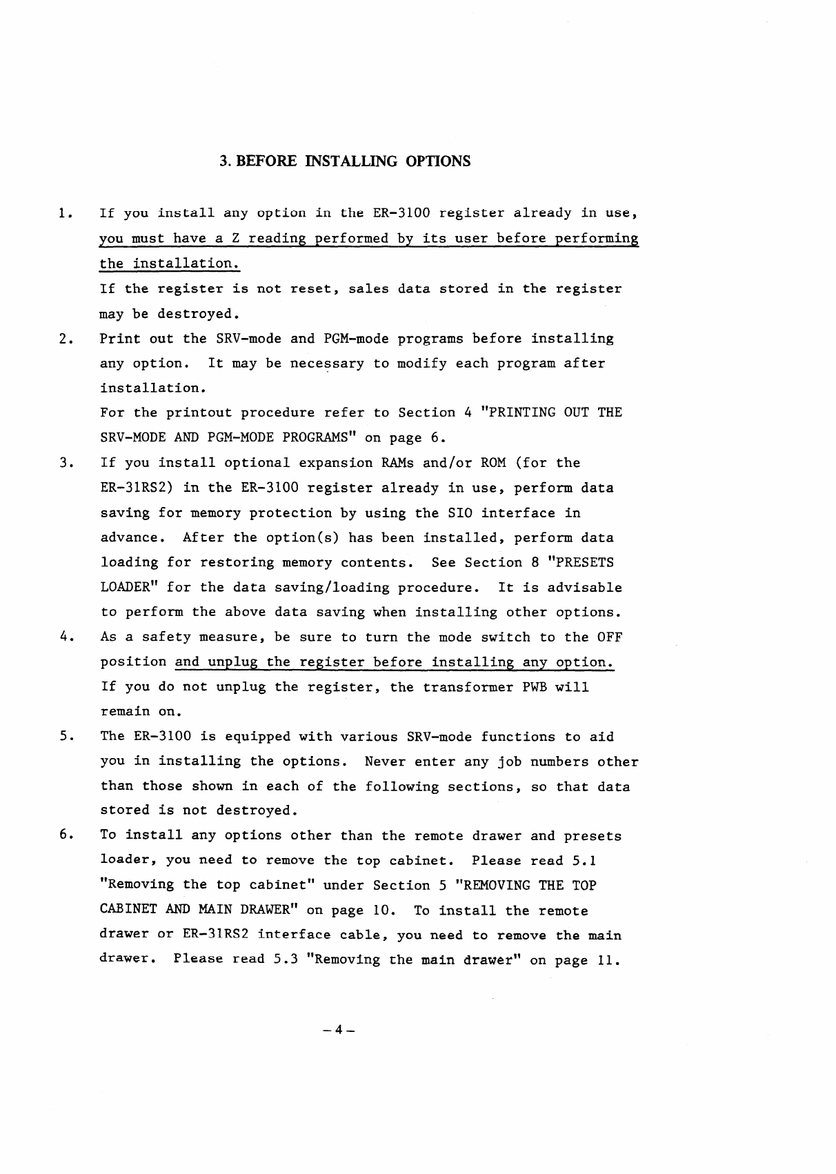
If you install any option in the ER-31OO register already in use,
you must have a Z reading performedby its user before performing
the installation.
If the register is not reset, sales data stored in the register
may be destroyed.
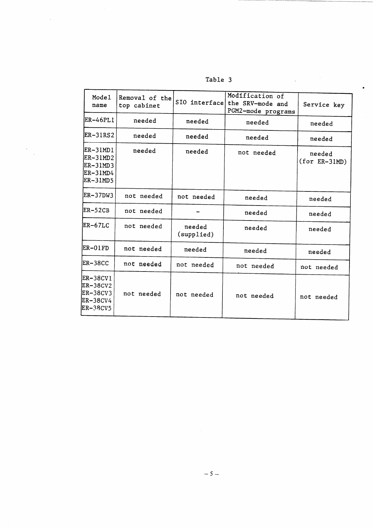
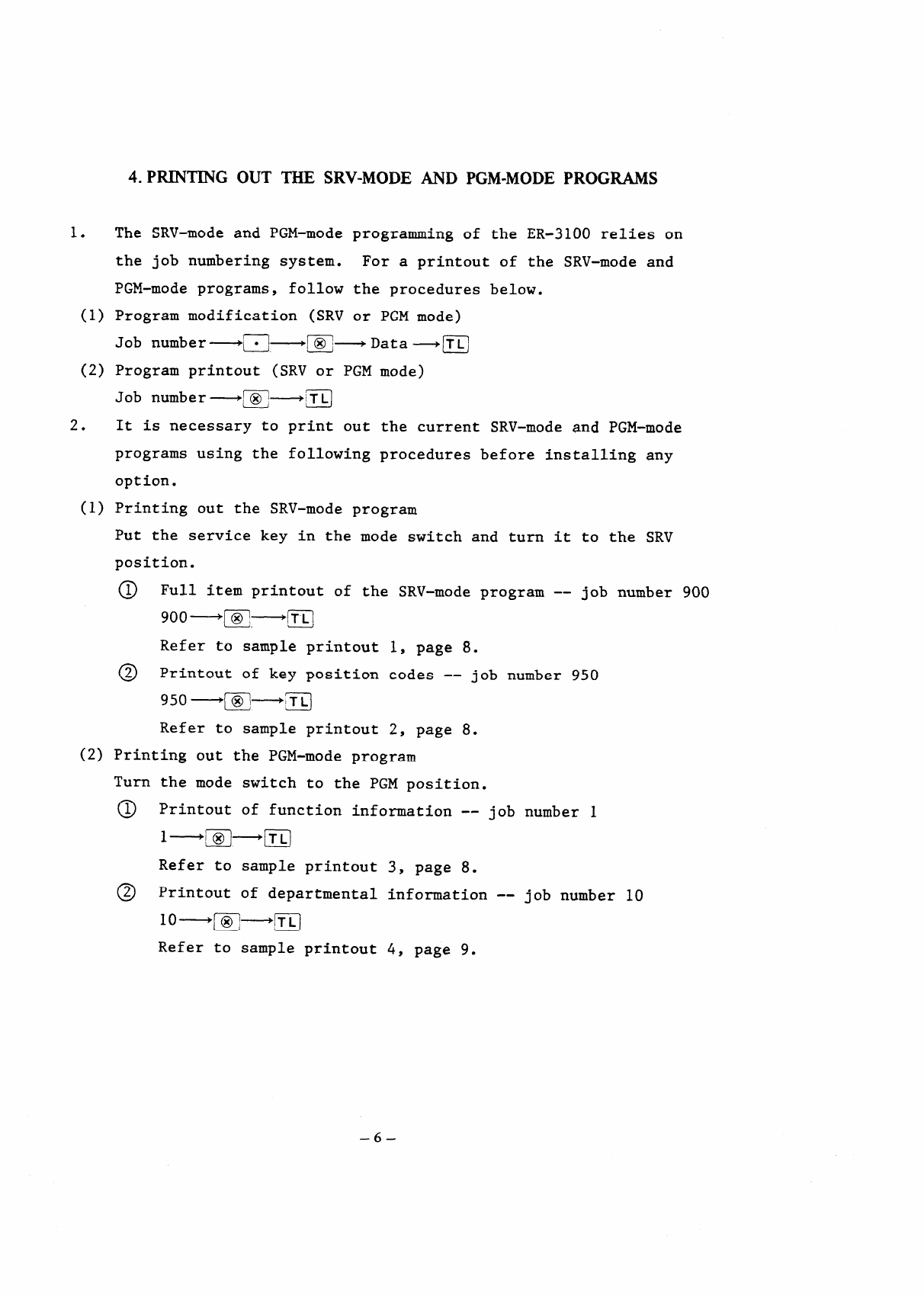
Print out the SRV-mode and PGM-modeprograms before installing
any option. It may be necessary to modify each program after
installation.
For the printout procedure refer to Section 4 “PRINTING OUT THE
SRV-MODEAND PGM-MODE PROGRAMS”on page 6.
If you install optional expansionRAMs and/or ROM (for the
ER-31RS2) in the ER-31OO register already in use, perform data
saving for memory protectionby using the S10 interface in
advance. After the option(s)has been installed,perform data
loading for restoringmemory contents. See Section 8 “PRESETS
LOADER” for the data saving/loadingprocedure. It is advisable
to perform the above data savingwhen installingother options.
As a safety measure, be sure to turn the mode switch to the OFF
position and unplug the registerbefore installingany option.
If you do not unplug the register, the transformerPm will
remain on.
The ER-31OO is equippedwith various SRV-mode functions to aid
you in installingthe options. Never enter any job numbers other
than those shown in each of the followingsections, so that data
stored is not destroyed.
To install any options other than the remote drawer and presets
loader, you need to remove the top cabinet. Please read 5.1
“Removing the top cabinet”under Section 5 “REMOVING~E TOP
CABINET AND MAIN DRAWER~ on page 10. To install the remote
drawer or ER-31RS2 interfacecable, you need to remove the main
drawer. Please read 5.3 “Removingthe main drawer” on page 11.
–4–

Table3 *
Modificationof
Model Removal of the S10 interfacethe SRV-mode and
name top cabinet Service key
PGM2-modeprograms
ER-46PLl needed needed needed needed
ER-31RS2 needed needed needed needed
ER-31MD1 needed needed
ER-31MD2 not needed needed
(for ER-31MD)
ER-31MD3
ER-31MD4
ER-31MD5
ER-37DW3 not needed not needed needed needed
—
ER-52CB not needed needed needed
ER-67LC not needed needed needed needed
(supplied)
&I
ER-OIFD not needed needed needed needed
ER-38CC not needed not needed not needed Hot needed
ER-38CV1
IER-38cv2I I I I
ER-38CV3 not needed not needed
ER-38CV4 not needed not needed
ER-38CV5
–5–

4.
1. The
the
P~~G OUT THE SRV-MODE AND PGM-MODEPROGWS
SRV-modeand PGM-mode programmingof the ER-31OO relies on
job numbering system. For a printout of the SRV-mode and
PGM-mode programs,follow the proceduresbelow.
(1) Program modification (SRV or PGM mode)
Job number—-m-m~ D
Data~TL
(2) Program printout (SRV or PGM mode)
Job number~ m—--m
2. It is necessary to print out the current SRV-modeand PGM-mode
programsusing the followingproceduresbefore installingany
option.
(1) Printing out the SRV-mode program
Put the servicekey in the mode switch and turn it to the SRV
position.
@ Full item printout of the SRV-modeprogram -- job number 900
E
9oo~ x~m
Refer to sample printout 1, page 8.
@ Printout of key position codes -- job number 950
950~ m—-m
Refer to sample printout 2, page 8.
(2) Printing out the PGM-mode program
Turn the mode switch to the PGM position.
@ Printout of function information-- job number 1
1~ m~m
Refer to sample printout 3, page 8.
@ Printout of departmentalinformation-- job number 10
10~~~ m
Refer to sample printout 4, page 9.
–6–

@ Printout of PLU information-- job number 20
Start PLU End PLU
code code
Refer to sample printout 5, page 9.
@ Printout of set PLU information-- job ~um~er 23
23~ m—-m
Refer to sample printout 6, page 9.
@ printout of cashier numbers -- job n~mber A()
40—~~ m
Refer to sample printout 7, page 9.
–7–

3. Sample printouts
Sample printout 1 Sample printout 2
(Printoutof the (printoutof the
SRV-modeprogram SRV-modeprogram
-- job # 900) -- job # 950)
YOURRECEIPT
01)01/00 0:13
HXSRV ~DE Y++
F(I1 a~fj~
Ftt2 0050
Fo~ 5010
F04 0000
FE Oooo
F06 0000
F07 0000
F08 ~o~
F09 0000
:< 00000
ZI 00000
Z2 00000
GT1 Ooooooooooo.oo
GT2 Ooooooooooo.oo
G-T3 00000000000.00
Oolomoo R
YOURRECEIPT
01/01/00 0:11
K105F’LU025083
RI06 F’L~96o84
K107F’LLJ027085
K108RU028 086
KI09 PLU029087
Kl10F’LU02d088
KillF’LU031of39
K112 F’LU032090
K113 Ru033 WI
K114PLU’i 09z
K115 mua~s093
K116RU074094
K1l?F’Lu037
09S
Kii8R1.K138096
K119PLU039097
K120F’LuD400?8
K121PLU04i099
KlZPLU042im
K123FLU043101
Ki24fiU044102
K125RU045103
KI26F’LUD46104
K176F’LU09613
K177PLU097155
K17SF’LU0981%
K179FLU099157
K180
F’LU1OOIW
Ooo?tlooo 9
Sample printout 3
(Printoutof the
PGM-mode program
-- job # 1)
YOURRECEIPT
ol/ol/cnl 0:18
I P#04 1
IP#m .0000
IF’#06 011
F#48
F#49
F#50
F#51
F#W
1=#57
F#58
F#59
F#60
F#61
Oollmoo
–8–

Sample printout 4
(Printoutof the
PGM-mode program
-- job # 10)
Sample printout 5
(Printoutof the
PGM-mode program
-- job # 20)
YOURRECEIPT
01/01/00 0:24
Y33PGN
Iml
mlPLu
Z#Gl
WLU
Mnl
mTPLu
4#al
Oo4PLu
5#Ql
WJPLU
$#01
O06PLU
7#Ql
O07PLU
8#ul
O08PLU
WE%%X
SET
-0.01
SET
-0.m
SET
-0.03
SET
-0.04
SET
-o.m
0.06
0.07
0.08
WI
098PLu 0.00
99#1
099PLu 0.00
lmcll
100PLU 0.00
oo18m $
Sample printout 6 Sample printout 7
(Printoutof the
PGM-mode program
-- job # 23)
YOURRECEIPT
SET
-0.01
mu 10
PLu11
PLu12
PLU 13
PLu 14
SET
-0.02
PLu 8
F’LU 9
PLU 10
SET
-0.03
SET
-0.04
SET
-0.05
SET
0.00
F’LU92
PLU 9S
PLu 94
fi
(Printoutof the
PGM-mode program
--job #40)
YOURRECEIPT
01/01/00 0:26
–9–

5. REMOVING THE TOP CABINET AND MAIN DRAWER
5.1 Removing the top cabinet (Fig. 1)
1. Turn the mode switch to the OFF position and unplug the cash
register.
Fix the front of the key sheet to the top cabinet by attaching
tape to two locations.
2. Raise the customer display by pulling it in the direction of the
arrow A.
3. Remove the two screws situated on the right and left sides of the
top cabinet. Then remove the printer cover and the screw at the
back of the cabinet. (Fig. 1)
4. Remove the top cabinet by moving it in the directionsof the
arrows B, C, and D in this sequence,
‘/
h‘\ n
Fix
A
..
\
–lo–

5.2 Replacing the top cabinet
Replace the top cabinet in the reverse order of removing,
When replacing the cabinet,use care to prevent the heat sink
from catching the cables that connect the display PWB and main
Pm.
Also, prior to fixing the top cabinetmake sure the interface
cable between the display PWB and the main PWB is securely
connected to the socket on the main PWB.
5.3 Removing the main drawer
1. Remove the two screws from the bottom of the drawer. (Fig. 2)
Fig. 2
2. Move the main unit forward (in the direction of the arrow a) and
lift upwards (the arrow b). (Fig. 3)
3. Disconnect the drawer connectioncable and grounding strap.
–11–

Fig. 3
5.4 Replacing the main drawer
1. Reconnect the drawer connectioncable and grounding strap.
2. Fit the pawls on the bottom of the main unit into the holes in
the drawer by moving the main unit in the directionof the arrow
c and move it backward (in the directionof the arrow d).
(Fig. 4)
Fig. 4
– 12–

3. Secure the drawer to the main unit by using the two screws
removed in step 1 of 5.3. (Fig. 5)
I
Fig. 5
–13–

6.1
0
0
0
0
0
0
6. RS-232C INTERFACE (ER-31RS2)
Outline
EIA (ElectronicsIndustriesAssociation)standard RS-232C is
associatedwith the transfer of binary serial data, control
signals, and timing signals between
The RS-232C interface is one of the
the exchange of informationbetween
device.
modems and data terminals.
devices generallyused for
a computer and a peripheral
This interface (ER-31RS2)was designed to conform to the EIA
standard,but in particular it was designed for connection
between the ER-31OO and a data processingmachine.
It becomes necessary to set communicationspecificationsof the
ER-31RS2 (e.g. baud rate) matched to those of the data processing
machine, when the ER-31RS2 is connectedwith a data processing
machine that is equippedwith the RS-232C2 interface.
The jumper-switch (Jl - J8) on the ER-31Rs interface circuit
board must be used to choose the specifications.
Refer to “RS-232C Specificationbook” publishedby Engineering
Department,ElectronicsIndustriesAssociation (EIA), for details
of RS-232C requirements.
Com~onents
The ER-31Rs2 consistsof the followingcomponents.
1) Interfaceboard unit (CPWBE6951RC06)
2) Control ROM (VH127256R223A)
Note: The version of the control ROM is indicatedby the last
characterof its part code. (This control ROM is version A.)
3) Connectingcable (QCNW-7059RCZZ)
4) Others
A) Ferrite core (RCORF6629RCZZ) 2 pcs.
B) Connector spacer for mini pitch (PSPAB2343RCZZ)2 pcs.
Connector spacer for inch pitch (PSPAB2333RCZZ) 2 pcs.
C) Screw (XUPSD30P08000) 2 pcs.
(XBPSD30P06KSO) 2 pcs.
–14–

6.2
1.
2.
D) Nut (XNESD26-20000) 2 pcs.
E) Spring washer (XWSPN26-06000) 2 pcs.
F) Grounding cable (QCNW-6791RCZZ) 1 pc.
Note: If the machine is equippedwith grounding cable, it is
not necessary to connect this cable (Fig. 9).
The cable and connector to be connected to the external
equipmentneed to be procured locally.
For the connector to be attached to the ER-31RS2 connecting
cable, use either of the followingthat can be mounted on the
bottom cabinet of the ER-31OO.
0 Mini pitch DB-C6-J1O-1 (JAE make) (SHARP part code:
LCHSM6656RCZZ)
“ Inch pitch DB-C6-JIO-2 (JAE make) (SHARPpart code:
LCHSM6657RCZZ)
Use a shielded cable for connectingcable.
Installationprocedure
Prior to installingthe ER-31RS2 perform data saving for memory
protection
procedure,
Remove the
by using the S10 interface. For the data saving
see Section 8 “PRESETSLOADER”.
top cabinet and main drawer. (Refer to Section 5 “
REMOVING THE TOP CABINET AND MAIN DRAWER”.)
Installationof the control ROM.
Remove the RAM PWB unit from the main PWB and connect the control
ROM to the ROM3 socket on the main PWB. (Note that the control
ROM is placed in the same directionas the ROM1 and ROM2.)
After the control ROM has been installed,replace the RAM PWB
unit.
–15–

Servicebattery
\~RAM PWBunit
RSTs
M
Notes: 1. The connectorsof the RAM PWB unit are both taped so
that it can resist vibrations during transportation.
Remove the tapes from the connectorsprior to the
installationwork and attach tapes again to the
connectorsafter completionof the installationwork.
2. Prior to removing the RAM PWB unit connect the
service
service
the RST
unit is
battery
entirelydestroyed. If this is the case, take master
resetting 1 when starting the ER-31OO.
The RAM data may be destroyedeven when the above
action is taken for memory protection. If the
ER-31OO cannot start normally after installingthe
control ROM, start it by master resetting 1.
It is advisable to perform data saving by using the
battery (CKOG-6626RCZZ)to this unit and the
connector (UKOGGO056CSZZ)to the ON side of
switch for memory protection. If the RAM PWB
removedwithout connectingthe service
and service connector,the RA.Mdata is
–16–
Other manuals for er-3100
1
Table of contents
Other Sharp Cash Register manuals

Sharp
Sharp ER-A310 User manual

Sharp
Sharp UP-X500XP User manual

Sharp
Sharp XE-A110 User manual

Sharp
Sharp ER-A520 Product guide

Sharp
Sharp XE-A42S Parts list manual

Sharp
Sharp XE-A303 User manual

Sharp
Sharp ER-3310 User manual

Sharp
Sharp ER-A520 Owner's manual

Sharp
Sharp XE-A407 User manual

Sharp
Sharp UP-800F Quick manual

Sharp
Sharp ER-A410 User manual

Sharp
Sharp ER-A610 User manual

Sharp
Sharp ER-A310 User manual

Sharp
Sharp UP-810F Owner's manual

Sharp
Sharp XE-A101 User manual

Sharp
Sharp XE-A303 User manual

Sharp
Sharp ER-A310 Owner's manual

Sharp
Sharp ER-2540 User manual

Sharp
Sharp XE-A101 User manual

Sharp
Sharp XE-A130 User manual