ER-A410/ER-A420 SPECIFICATIONS
– 4 –
■
■■
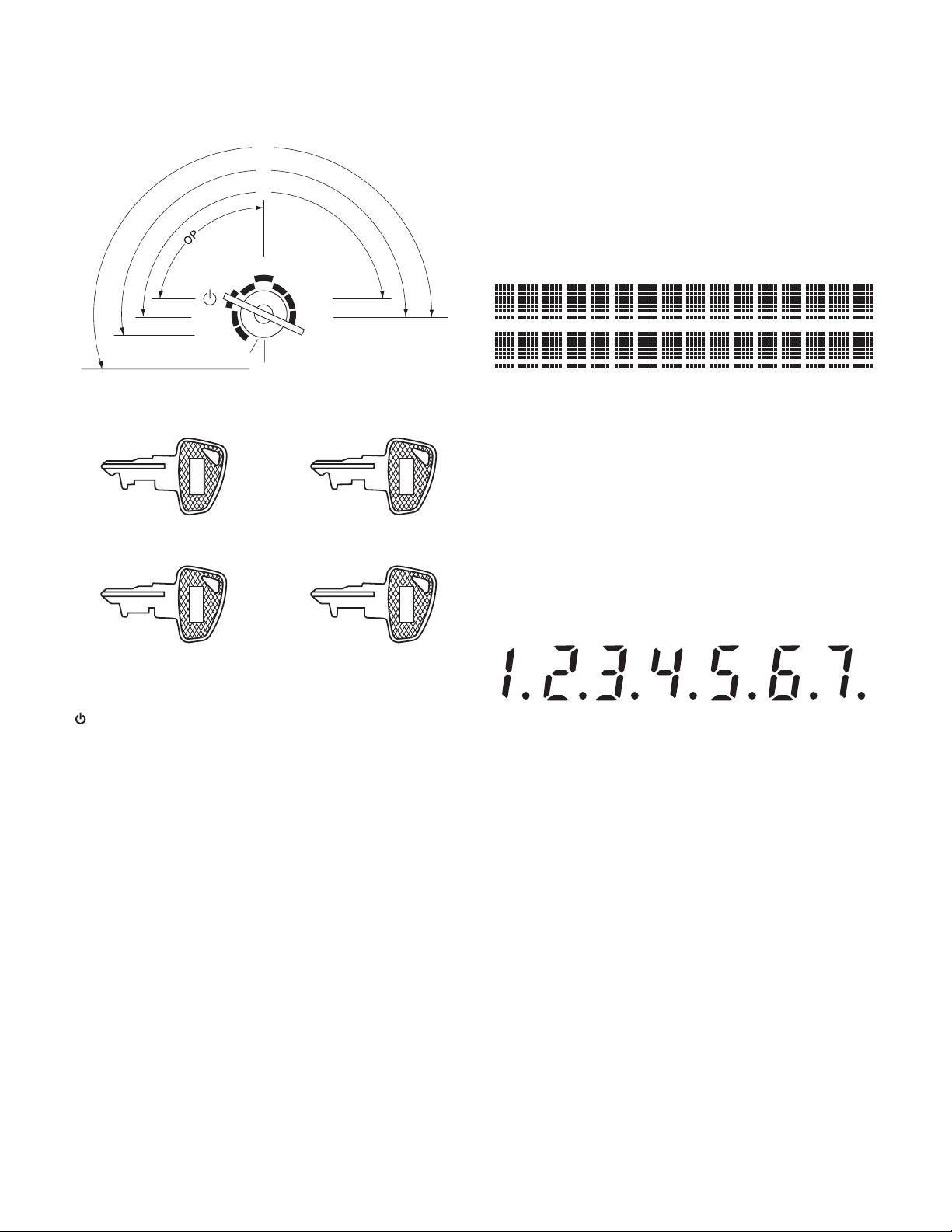
■Operator display
The operator display consists of a 2-line LCD dot-matrix display (16
characters/line).
• Cashier/clerk code or mode name
The mode you are in is displayed. When a cashier/clerk is
assigned, the corresponding cashier/clerkcode is displayed in
the REG or OP X/Z mode. For example, “0001” is displayed
when cashier 0001 is assigned.
• Repeat
The number of repeats is displayed, starting at “2” and incremen-
tal with each repeat. When you have registered ten times, the
display will show “0”. (2 33......9 30 31 32...)
• Sentinel mark
When the amount in the drawer reaches the amount you prepro-
grammed, the sentinel mark “X” is displayed to advice you to
remove the money to a safe place.
• Power save mark
When the cash register goes into the power save mode, the
power save mark (decimal point) is displayed.
• Stock alarm indicator
When the stock of the PLU which you entered is zero or nega-
tive, the alarm indicator (decimal point) is displayed.
• Function message display area
Item labels of departments and PLU/subdepartments and func-
tion texts you use, such as %1, (–) and CASH are displayed
here. For the details of function texts.
When an amount is to be entered or entered, “AMOUNT” is dis-
played: When an amount is to be entered, – – – – – – – is dis-
played in the numeric entry display area with “AMOUNT”. When
a preset price has been set, the price is displayed in the numeric
entry display area with “AMOUNT”.
• Numeric entry display area
Numbers entered using numeric keys are displayed here.
Date and time display
Date and time appear on the display in the OP X/Z, REG, or MGR
mode. In the REG or MGR mode, press the [#] key to display the date
and time.
Error message
When an error occurs, the corresponding error message is displayed
in the function message display area.
■
■■
■Customer display (Pop-up type)
6. PRINTER
6-1. PRINTER
6-2. PAPER
6-3. LOGO STAMP
• No
6-4. CUTTER
• Method: Manual
Function message
displayarea
Cashier
/
clerkcode or
mode name
Numeric entry
displayarea
Receipt OFF indicator("_")
/
Stockalarm indicator(" ")
Repeat
/
Sentinelmark
/
Powersave mark
Dept.name
/
PLU name
/
function text
Price level
/
PLU level
(e.g.P2L3)
Power save mark(This markappears only inthe power save mode)
• Part number: PR-45MII (PR-45M compatible)
• NO. of station: 2 (Receipt and journal)
• Validation: No
• Printing system: Line thermal
• No. of dot: Receipt 288 dots
• Journal 288 dots
• Dot pitch: Horizontal 0.125mm
Vertical 0.125mm
• Font: font A: 12 dots x 24 dots
font B: 9 dots x 24dots
• Printing capacity: Receipt max. 24 characters
Journal max. 24 characters
• Character size: 1.5mm (W) x 3.0mm (H) at 12 x 24 dots
1.125mm (W) x 3.0mm (H) at 9 x 24 dots
• Print pitch: Column distance 1.5mm at 12 dots
1.125mm at 9 dots
Row distance 3.75mm
• Print speed: Approximate 50mm/s
• Paper feed speed:
(Manual feed) Approximate 40mm/s
• Reliability: Mechanism MCBF 5 million lines
• Paper end sensor: Set up (Receipt and journal)
• Cutter: Manual
• Near end sensor: No
Note : PR-45MII is minor change model of the PR-45M.
This printer is not set gear cover (GCOVH7146BHZZ) from PR-
45M only.
• Paper roll dimension: 44.5 m0.5mm in width
Max. 83mm in diameter
• Paper quality: (Journal/Receipt)
High-quality paper
paper thickness: 0.06 to 0.08mm