manuals.online logo
Brands
  1. Home
  2. •
  3. Brands
  4. •
  5. Sharp
  6. •
  7. Cash Register
  8. •
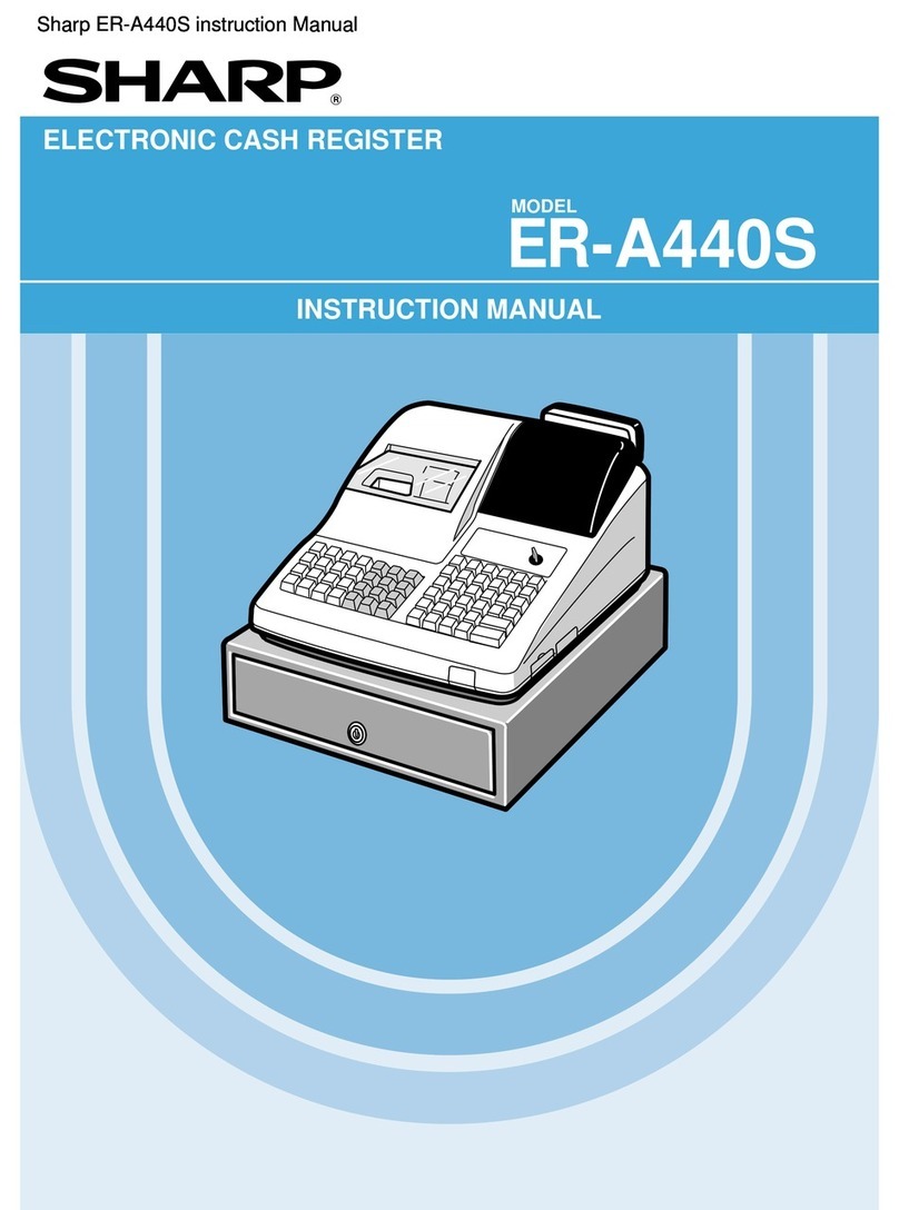
  9. Sharp XE-A110 User manual

Sharp XE-A110 User manual

Other manuals for XE-A110

3

This manual suits for next models

1

Other Sharp Cash Register manuals

Sharp XE-A107 User manual

Sharp

Sharp XE-A107 User manual

Sharp XE-A201 User manual

Sharp

Sharp XE-A201 User manual

Sharp UP-600 User manual

Sharp

Sharp UP-600 User manual

Sharp XE-A206 Parts list manual

Sharp

Sharp XE-A206 Parts list manual

Sharp ER-A320 Owner's manual

Sharp

Sharp ER-A320 Owner's manual

Sharp XE-A402 User manual

Sharp

Sharp XE-A402 User manual

Sharp XEA102 - Cash Register User manual

Sharp

Sharp XEA102 - Cash Register User manual

Sharp ER-A520 User manual

Sharp

Sharp ER-A520 User manual

Sharp XE-A106 User manual

Sharp

Sharp XE-A106 User manual

Sharp ER-3550 User manual

Sharp

Sharp ER-3550 User manual

Sharp ER-A410 User manual

Sharp

Sharp ER-A410 User manual

Sharp ER-A250 User manual

Sharp

Sharp ER-A250 User manual

Sharp ER-A247 Mounting instructions

Sharp

Sharp ER-A247 Mounting instructions

Sharp ER-1873 User manual

Sharp

Sharp ER-1873 User manual

Sharp ER-A440 User manual

Sharp

Sharp ER-A440 User manual

Sharp XE-A101 User manual

Sharp

Sharp XE-A101 User manual

Sharp ER-A440 User manual

Sharp

Sharp ER-A440 User manual

Sharp XE-A201 User manual

Sharp

Sharp XE-A201 User manual

Sharp ER-1017 User manual

Sharp

Sharp ER-1017 User manual

Sharp ER-A320 User manual

Sharp

Sharp ER-A320 User manual

Sharp XE-A301 Quick start guide

Sharp

Sharp XE-A301 Quick start guide

Sharp ER-2386S User manual

Sharp

Sharp ER-2386S User manual

Sharp ER-2540 User manual

Sharp

Sharp ER-2540 User manual

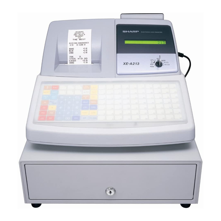
Sharp XE-A213 User manual

Sharp

Sharp XE-A213 User manual

Popular Cash Register manuals by other brands

Royal 480nt operating manual

Royal

Royal 480nt operating manual

Olivetti ECR 8200 S user guide

Olivetti

Olivetti ECR 8200 S user guide

TEC TEC FS-3600 owner's manual

TEC

TEC TEC FS-3600 owner's manual

Integrated System Laboratory ISL 4006 user manual

Integrated System Laboratory

Integrated System Laboratory ISL 4006 user manual

Sam4s ER-380 Operation and program manual

Sam4s

Sam4s ER-380 Operation and program manual

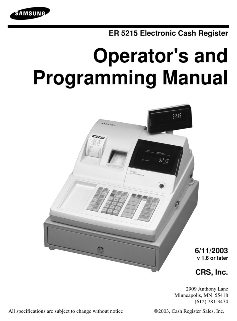
Samsung ER 5215 Operator's manual

Samsung

Samsung ER 5215 Operator's manual

Toast Toast Quick setup guide

Toast

Toast Toast Quick setup guide

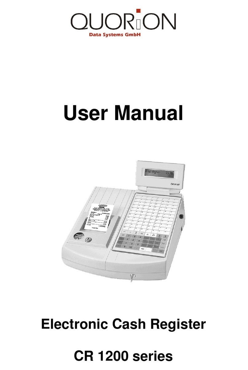
QUORION CR 1200 user manual

QUORION

QUORION CR 1200 user manual

Olivetti ECR 7700 LD eco Plus user guide

Olivetti

Olivetti ECR 7700 LD eco Plus user guide

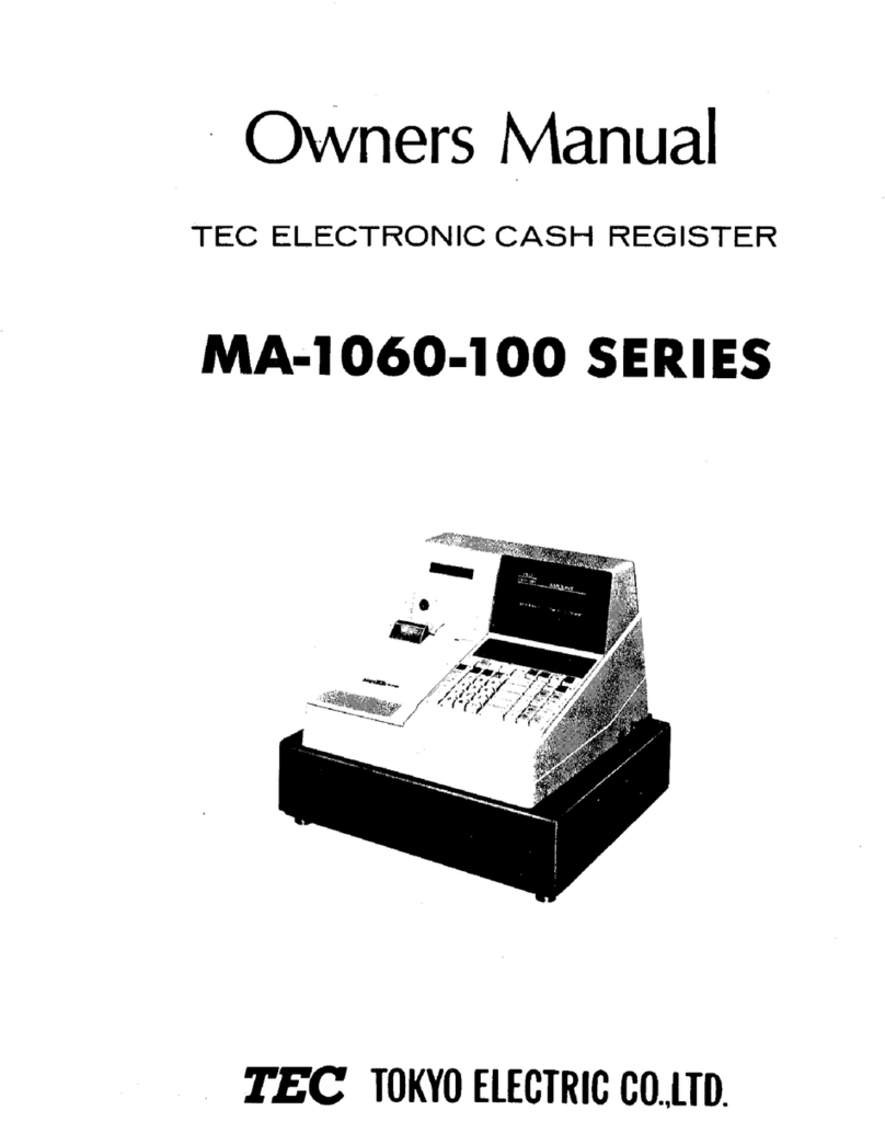
TEC TEC MA-1060 owner's manual

TEC

TEC TEC MA-1060 owner's manual

American Changer CLASSIC Series Operation manual

American Changer

American Changer CLASSIC Series Operation manual

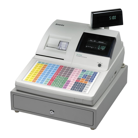
Sam4s ER-5100? SERIES Service manual

Sam4s

Sam4s ER-5100? SERIES Service manual

Casio PCR-T273 user manual

Casio

Casio PCR-T273 user manual

Casio QT-7300 Series user manual

Casio

Casio QT-7300 Series user manual

GALEB GP-100 user manual

GALEB

GALEB GP-100 user manual

Optimas OP-680 manual

Optimas

Optimas OP-680 manual

TEC MA-600 Series owner's manual

TEC

TEC MA-600 Series owner's manual

Sam4s ER-180 Operation manual

Sam4s

Sam4s ER-180 Operation manual

manuals.online logo
manuals.online logoBrands
  • About & Mission
  • Contact us
  • Privacy Policy
  • Terms and Conditions

Copyright 2025 Manuals.Online. All Rights Reserved.

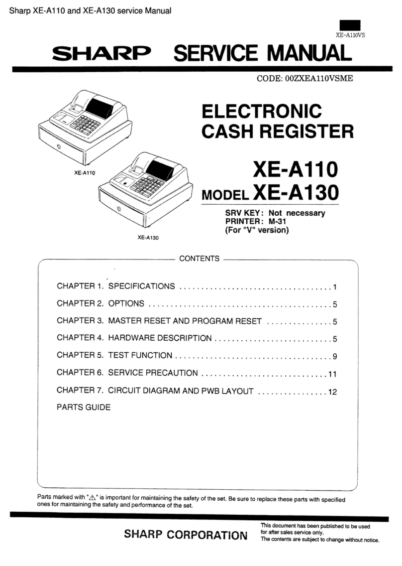
XE-AIIOVS
SHARP SERVICEMANUAL
CODE: OOZXEA11OVSME
ELECTRONIC
CASH REGISTER
SRV KEY: Not necessary
PRINTER:M-31
(For “V”version)
XE-A130
CONTENTS \
CHAPTER
CHAPTER
CHAPTER
CHAPTER
CHAPTER
CHAPTER
CHAPTER
1.
2.
3.
4.
5.
6.
7.
‘SPECIFICATIONS
OPTIONS . . . . . . .
. . .
. . .
MASTER RESET AND
..........
..........
PROGRAM
HARDWARE DESCRIPTION .....
TEST FUNCTION ..............
SERVICE PRECAUTION ........
......................1
......................5
RESET . . . . . . . . . . .. ...5
......................5
......................9
.....................11
PARTS GUIDE
CIRCUIT DIAGRAM AND PWB LAYOUT ................12
Parts marked with “A” is important for maintaining the safety of the set. Be sure to replace these parts with specified
ones for maintaining the safety and performance of the set.
SHARP CORPORATION This document has been published to be used
for after sales service only.
The contents are subject to change without notice.
XE-A11OVS
CHAPTER 1. SPECIFICATIONS
1. Appearance
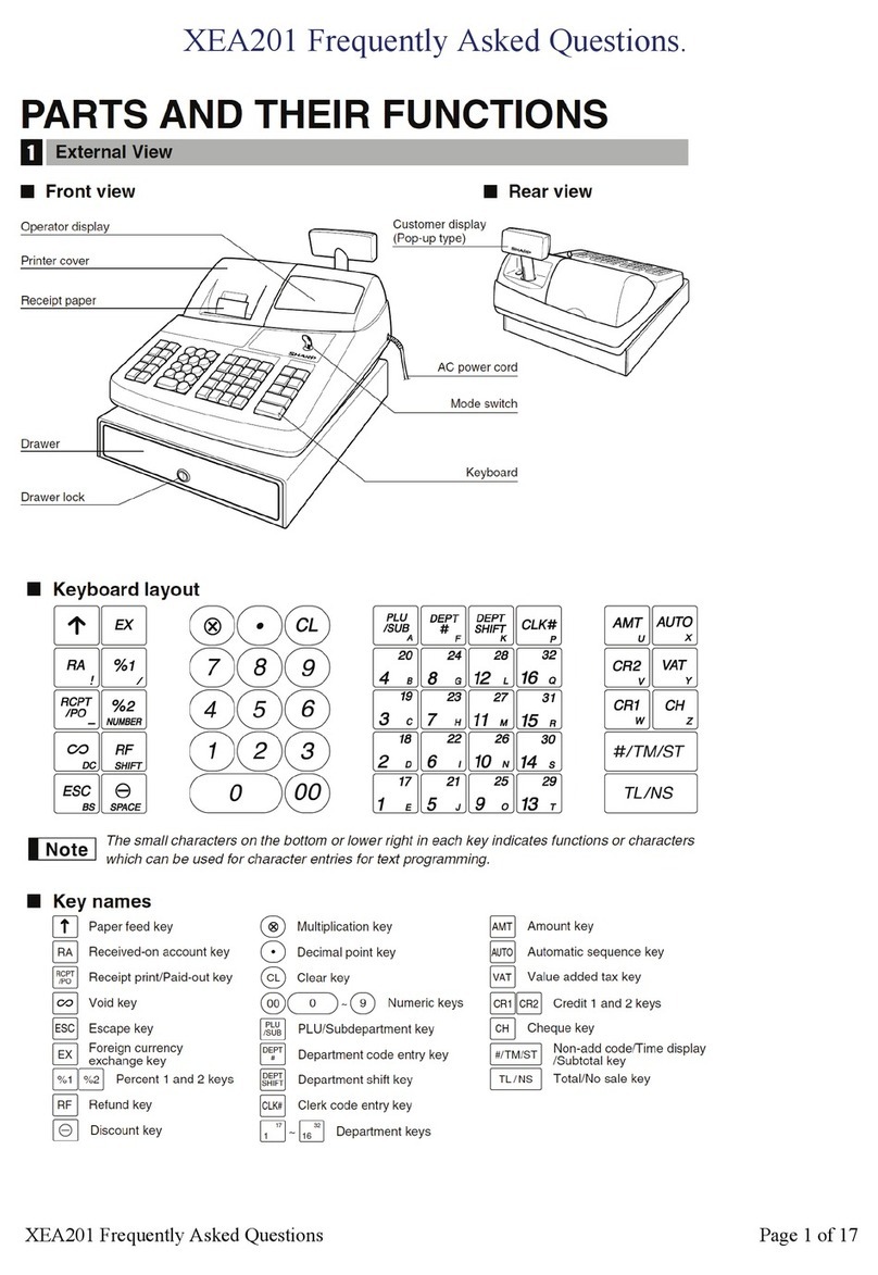
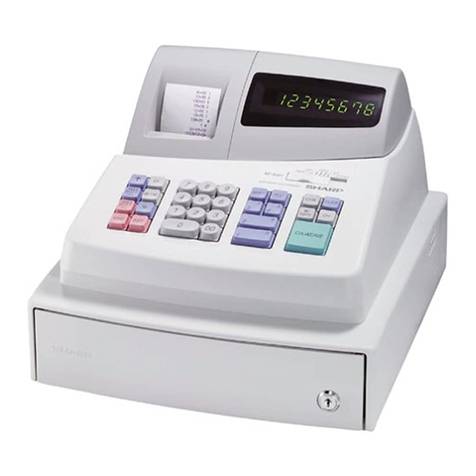
Front view
XE-AI 10 XE-A130
2. Rating
XE-A110 XE-A130
Version SEEG SUK SCA SEEG ISUK SCA
(Country) (GERMANY) (U.K.) (AUSTRALIA) (GERMANY) (U.K.) (AUSTRALIA)
Weight 4.0 kg 4.3 kg 10.0 kg
External dimension (Including the drawer) 330 (W) x380 (D)x218 (H) mm 420 (W) x423 (D) x234 (H) mm
Power source AC 230V (fl O”/.),60 Hz
Ambit temperature, humidity 0- 40*C (32 to 104”F)
10- 90”C
3. Keyboard
1)Keyboard layout
@XE-A11O
Type Normal keyboard
Key position STD/MAX 27
Key pitch 19 (w) x19 (h) mm
Kev Iavout FixedtvDe I
B
T@nM~L
789
456
123
0‘00
VAT Po m
RA Q/o
D4m
CJ-i CR
m3
#/ST
n2
TUAT/NS
P1E
@XE-A130
Type Normal keyboard
Key position STD/MAX 31
Key pitch 19 (w) x19 (h) mm
Key layout Fixedtvc)e
IVAT
&
456
123
000
m
iPo @
5[
RA %
m4m
wCR
m3
#/ST
m2
TUAT/NS
P1E
2) Key List
KEYTOP DESCRIPTION XE-A110 XE-A130
0to 9,00 Numeric keys o0
CL Clear key Go
@/TM Multiplication/
Time display key ox
Ie~Discount key xo
I
DEPT. 1-4 IDepartment 1-4 keys ox
!
DEPT. 1-5 IDepartment 1-10 keys xo
TPaper feed key o0
RA Received on account key o0
Po Paid out key o0
0/0 %key o0
Void key o0
#/ST INon add codel
~Tax included subtotal key o0
CH ~Check key o0
k
CR ICredit key o0
TMAT/NS Total/Amount tender/
No sale key o0
+
IVAT IVAT kev 1010
@Multiplication key xo
TM Time disI)lav kev xo
IRF \Refund kev Ixlo
-1-
4. Mode Switch
1)Layout
@XE-A11O
●Slide type
&CAL ~EG XFLASH ZPGU
Ir--’ I
I1I1
@XE-A115
●Rotary type REG
CAL IX/FLASH
OP key: “POWER OFF” mode to “REG” mode.
MA key: “POWER OFF” mode to “Z/PGM” mode.
*The keys can be inserted or drawn out in “REG” and “POWER
OFF” position.
@(POWER OFF): Switching off the display to prevent keyboard
entries.
CAL: Calculator mode,
REG: Various registrations.
WFLASH: Reading of any daily totals/Display reading of
some daily totals and limit overriding.
ZIPGM: Resetting of any daily totals/PGM programming.
5. Display
1) Operator display
Displaydevice: LED numeric display
Number of line: 1line
Number of positions: 9positions numeric display
Color of display: Red
Character size: Numeric 14.2 (H) x7.8 (W) mm
(Layout)
2) Customer display (Only XE-A130)
Displaydevice: LED numeric display
Number of line: 1line
Number of positions: 7positions numeric display
Color of display: Red
Style: Rear
Character size: Numeric 14.2 (H) x7.8 (W) mm
.m-Allovs
3) Display contents
hDisplay !Description
position
Amount I8-1 ~
Minus sign I9-2 I–: Floating
Error 9IE
PGM Mode 91P
CA/AT/NS [9 ~F:Lightsup when aregistration is
CHARGE Ifinalized by depressing
CHECK TUAT/NS, CH or CR Key.
Subtotal or shod i90
tender
Change 9C:Lights up whenever the change
due amount appears in the
Idisplay.
Department 9–8 No zero-suppressed.
Repeat 8Endless count, stafiing from 2
Decimal point 3-1 ITAB
Low battery 9L:Lights up when the voltage of
the battery for memoty
retention is lower than the
reaulated voltaae.
6. Printer
1)Printer
@M-31 (For XE-A11O)
●Model name:
●No. of stations:
●Printing system:
●Printing capacity:
oCharacter size:
●Print pitch:
●Print speed:
M-31
1
Print wheel selective type
Journal -13 characters
1.6mm (W) x2.8mm (H)
Column distance 2.lmm (numeric to numeric),
2.6mm (numeric to symbol)
Row distance 4.6mm
Approximate 1.4 lines/s
●Paper feed speed: Approximate 4.3 lines/s
●Reliability: MCBF 0.3 million lines
@M-42V {For XE-A130)
●
●
●
●
●
●
●
●
●
Model name:
No. of stations:
Printing system:
Printing capacity:
Character size:
Print pitch:
Print speed:
M-42V
1
Print wheel selective type
Journal -19 characters
1.6mm (W) x2.8mm (H)
Column distance 2.1mm (numeric to numeric),
2.6mm (numeric to symbol)
Row distance 4.6mm
Approximate 2.2 iines/s
Paper feed speed: Approximate 8.0 lines/s
Reliability: MCBF 0.7 million lines
(Layout)
-2-
XE-A11OVS
2) Paper
●Paper roll dimension: 57.5N.5mm
max. 80 mm in diameter
●Paper quality: Journal
Bond paper (paper thickness: 0.06to
0.085mm paperweight: 47 to 64g/m2)
3) Inking
●Ink supply system: Ink rill
●Form: Roller
●Specification: Material –rubber
●Ribbon life: 1million characters
●Print color: purple
4) Logo stamp (No)
7, Drawer
[Outline]
●
●
●
Standard equipment: Yes (1)
Max. number of “
connectable drawers: None
The drawer consists of:
(1) Drawer box (outer case) and drawer
(2) Lock (attached to the drawer)
[Specification]
1)Drawer box and drawer
@Except for XE-A130 SCA (Australia) and SUK (U.K.) version
IModel nameofthe drawer box ISK-380 I
ISize I330(W) x380 (D)x94 (H) I
5) Cutter (No) Color Gray 6
Material Plastic
6) Printing wheel layout
@M-31
1 2 3 4 5 6 7 8 9 10 11 12 13
0 010 0 0 0 0 ~o 0 0]0 o‘o]x
1I
1 111 ‘1 111~1 1 1‘1 1 1 z
222 2 2 2 212 2 2 2 2 2 RA
333 3 3 3 3 ~333 3 3 3 /PO
4 4 4, 4 4 4 414 4 ,4 4 4 4 Ivl)
I
555!5 5 5 ,515 515’ 555‘/0
66616 6 6 6 6 6/6 6 6 6 @
77~717 777‘7 7777 7 ST
88~818 8 8 8 8 888‘8 8TX
(
99[9\9 99“ 9 9 919 9 9 9 ICA
10 ~I1
31 –~–~- –-–––\– ––-ICH
,
12 i~,,. ]CK
13 # i#;#,####1#~#~#~# #ICG
@M-42V
1 2 3 4 5 6 7 8 9 10 11 1213 141516 17 18 19
00/0 Ojo oio ‘0/0 oo~o ‘O~O~OIO]o~oICA L
I
1 111 1’1 ‘1 111,1 ‘Ill 111 1]1 11CH 1
2 2 ~2I22222\2[212[2 212 2 2 2 2RA 2
!
3 313 3 3 3 3 3 [3~3~3[3333333Po 3
4 414 4 4 4 4 4 4 414 4 4 4 4 4 4 4INT 4
5 515 5,5 5 5 5 5 5 5 ,5 515 5 5 5 5 ST CK
66\6 61616 6666‘6 66~6 6 6 6 6AT +
7 7 7 717 7 777777717’ 7 7 7 17 CG -
,
8 8 8 8 I8, 88888888]8 8 8 8 8Tx x
9 9 99/9~91 919 9 999919 9 919 9RF @
10 – --1-\-~- ------/-,- - - -
11 ,,,l,i,~, , , , , , ,!, , , , ,*#
12 . . .~.l.~, ... . .\. i. . . . . y. NS
13 # ,# #~#I#I#~####l#\#!# # # # #VDTA
Bell —
Release lever Standard equipment; situated at
the bottom
Drawer open sensor i– I
@For XE-A130 SCA (Australia) and SUK (U.K.) version
Model name of the drawer box ISK-423 I
Size I420 (W) X423 (D) X114 (H) I
Color Gray 6
Material Metal
Bell l–
Release lever Standard equipment; situated at
the bottom
IDrawer open sensor l–
Separation from the main unit Disallowed
-3-
XE-A11OVS
2) Money case
@Exceptfor XE-A130 SCA (Australia) and SUK (U.K.) version
Separation from the drawer Disallowed
Coin case Fixed type
Number of compartments 4f3/5c
Layout: ❑
4B15C
@For XE-A130 SCA (Australia) and SUK (U.K.) version
Separation from the drawer Allowed
Separation of the bill components from Disallowed
the coin compartments
Bill separater Standard
Number of compartments \4B/8C
3)
●
●
Bill saparator: lpc
4B18C
Lock (LOCK KEY: LKGIM7331BHZZ)
Location of the lock: Front
Method of locking and unlocking
To lock, insert the drawer lock key into the
●Key No.:
lock and turn it 90 degrees counter clock-
wise.
To unlock, insert the drawer lock key and
turn it 90 degrees clockwise.
SKI-1
8. Battery
1)Memory backup battery
For memory back up, the dry battery ULM-3 (3 pieces) are needed.
1.
2.
2)
Memoy holding time:
Approx. 1year after NEW dry batteries are inserted.
Battery exchange method:
When the low battery symbol “L” lights up, replace the batteries (3
AA) replaced by the following method, within 2days.
1) Power on the ECR.
2) Mode switch turn to “REG” mode.
3) Remove the OLD dry batteries (3 pieces).
4) Insert the NEW dry batteries (3 pieces).
5) Confirm the low battery symbol “L” is off.
Low battery
Low battery indication will appear on left side of display when the
battery voltage is low.
CASE 1: When sitting idle or afier completion of transaction.
The machine can indicate the low battery condition. (Always)
CASE 2: Low battery indication will not appear during key opera-
tions, but will appear after power up of the cash register.
[Display sample]
u0.00u:Battery is OK.
“L 0.00 “:Low battery (You have to change the batteries.)
After finalization
“F 12.34“ :Battery is OK.
“L 12.34“ :Low battery. (“L” indicate instead of “F”.)
3) No battery
If the user forgets to replace the battery and the battery voltage falls
below acertain level, or if apower failure occurs with no battery
installed, memory contents cannot be retained. The CPU judges it as
no battery and perform the master reset. In this case, all the settings
and registrations are cleared. If, however, the power is supplied to the
AC cord, even though no battery is installed, memory contents are
retained.
-4-
XE-A11OVS
CHAPTER 2. OPTIONS
1. Options (No)
2. Service options (No)
3. Supplies
NO. NAME PARTSCODE PRICE RANK DESCRIPTION
1. ROLL PAPER DPAPR 10 25CSZZ AS 5ROLLS/PACK
2. ,INK ROLLER NR~LR 10 22CC05 AF
4. Special service tools (No)
CHAPTER 3. MASTER RESET
Master reset: Clears all the memory and initializes each preset
parameter.
Master reset should be performed by using the following procedure.
1. Turn off the power (Power OFF). (See Note 1,)
2. Let the ECR be without the memory backup battery.
3, Turn the mode switch to the others of Power-off position.
4. Turn on the power (Power ON). (See Note 2.)
When the master reset is completed, the buzzer sounds intermittently
three times.
5. Attach the memory backup battery to the ECR.
The master reset can also be accomplished in the following case.
(See Note3.)
Note 1) Power OFF: Means stopping the AC power supply to the
machine.
(Specifically, unplugging the machine.)
Note 2) Power ON: Means supplying the AC power to the machine.
(Specifically, plugging in the machine.)
Note 3) In case power failure occurs when the machine has no bat-
tery attached to it, the master reset operation is automatically
performed after the power has been restored.
This is because if power failure occurs with no battery at-
tached to the machine, all the memory is lost and the
machine does not work properly after power recovery;
this requires the master reset operation.)
CHAPTER 4. HARDWARE
DESCRIPTION
1. Block diagram
m-y
E
‘Printer DrwerIC
M-31
(XE-A1 10) Tumungsignal
or
M*V Drawer
[XE-Al~) ~Eox ,Driver
LLSI
.Ci3650
d
Vo’
-5-
XE-A11OVS
2. CPU (LC8650) Pin configuration
—
I
NO. ~PIN NAME SIGNAL NAME ~DESCRIPTION [IN/OUT IACTIVE ~Powerintemption
1{Usedfortimerinterruption)
II1
1:Plo/soo RWND ,REWINDMOTOR OUT ,HIGH ~‘LOW ‘ ‘
2;PI l/SIO/SBO MTR MOTOR FOR M42V/M31 OUT HIGH ~LOW
3;P12/SCKO TRG PRINTSOLENOID IOUT ~HIGH LOW
4~P13/sol DR DRAWER IOUT IHIGH LOW
5~P14/Sll/SBl ~NOTUSED OUT LOW ~LOW
I
6~P15/SCKl ~NOT USED OUT LOW LOW
7;p16/Buz ‘BZ ~BUZZER ,OUT \HIGH/LOW ILOW
8~P171PWM \NOTUSED 1OUT LOW iLOW
9ITESTI TEST ~NOT USED ,
!I
10 /RES /RES ~RESET IIN LOW IN
11 ~XT1 iXT1 ISUB CLOCK I
12 1XT2 \XT2 ~SUB CLOCK !
13 IVss GND \GND ~
14 ~CF1 xl IMAIN CLOCK II
,
15 CF2 x2 MAIN CLOCK I
I!
16 VDD VDD VDD I!
I
17 ,P80/ANo KR1 ,KEY RETURN 1IIN ~HIGH IIN
LOW
LOW
,m,,’
–6–
XE-A11OVS
3. Clock generator 5. RESET circuit
The Xl generator 32.768KHz which is primarily used to update the
internal RTC (Real Time Clock).
The X2 generator 12MHz which is used as main clock.
4. P-OFF circuit
frompower suppty circuit
f>
T
Vo m
ZD1
\\ ‘M -,
$;;K
AI MTZ6.2B:XE-A110\
MTZ6.2A:XE-A130\R6
D5 10OK
!R4 1C7
5.6K ~3.31JF/50V
I
POF
When the power is supplied, vottage Vo from the power supply circuit
rises. When it reaches about 6.2V, point Ais driven to HIGH so that
the POF signal of the CPU is fixed to HIGH with Vcc and the CPU
performing power ON process.
When voltage Vo falls below about 6.2V by turning off the power,
point Ais driven to LOW to fix the POF signal of the CPU to LOW and
the CPU performs power OFF process.
Since Q1 is turned on by Vcc, the RES signal is driven to LOW to
reset the CPU. After that, discharging of C8 turns off Q1 to drive the
RES signal to HIGH.
6. Printer circuit
TRG‘I
Drwer
,#
~~ Trriggermagnet
Ic
IIVcc I
to‘~ SubTimingpulsdetector
mI
1
RI
%y %.’~ Reseipulsdetector
II,
I I
1JI
7. REWIND motor drive circuit
b
hJMOTOR
R1o
Fiwm Q2
IK
7
C37M
Rll
15K
When the RWND signal from
operate the motor. the CPU is HIGH, Q2 is turned on to
8. DRAWER drive circuit
T
Vo
F>“-””
R12
OR 03
TK ,C3784
4
R13
1%
I
-7-
When the DR signal from the CPU is HIGH, Q3 is turned on to
operate the solenoid.
XE-A11OVS
Keyboard circuit 10. Display circuit
\\\,
CPU
I
‘sT’-KST”‘&2T24s”
Key Mode
Matrix Svuitdl
~KR2-KR5 I~
1.
1
lms
-:+30-1Oops
ST1 .,
.,
ST2 :
KSTn nn
n=l-4, m=5-8
KSTm nh
KST2 -KST5 of the key strobe signal are used as the Mode switch
strobe signals.
CPU
CPU ““’’””Y*I I I1
II
ST1-5 -
SA1-~1
4
4C3198
2.2K
SDP1
lx
One strobe signal drives two-digit LED.
-8-
CHAPTER 5. TEST FUNCTION
1)To execute the diag test, set the mode switch to Z/PGM, enter a
desired JOB code, and press PO (paid out) key.
2) The test message is printed by the printer.
3) Test contents and key operations
No. ~Test contents !KevoDerations
fI.!
1Mode SW test I1+~
2Key test —02 + ~
3Display buzzer test 3+ ~
4Drawer test 4+ ~
5Printer test ~5+ ~
6,CPU version No. print ~6A ~
7IBattery level test I7+~pol
1. Mode switch test
1) Keyoperation
2) Test procedure
Change over the mode switch as shown in 3). If the mode switch data
in the proper sequence is not read with the above operation, an error
print is made.
To cancel this test mode, set the mode switch from aposition other
than 2PGM to Z/PGM. In this case, the completion print is made.
During the test, the display indicates hard codes which correspond to
switch positions.
3) Mode switch operation
Mode: Z/PGM +WFLASH +REG +CAL +(!) w~PGM
Display: (04) (03) (02) (01) k(0.00)
No check when
returning the
switch to Z/PGM.
Completion print 01
Error print ########ol
3) Key check sequence
There is no specified key check sequence. Pressing TL/AT/NS key
terminates the key check and starts comparison with the sum check
data.
Completion print 02
Error print ########02
No, IModel ISumcheck data Production start
1XE-A11O [946 Jun. 1995
2XE-A130 I1107 Jun. 1995
The hard codes shown below are added in the hexadecimal system
and the lower two digits of the total are converted into the decimal
number, which is the sum check data.
Sum check data table (Keys which are shaded as ~are not used.)
@XE-A11O
m15 14
? 05 04
25 24 03
35 34 23
32 44 02
45 75 55
@)(E-A130
m15 14
TI05 ~04
I
25 ~24 03
35 ~34 ~23
32 ~44 02
45 75 55
13 22 42
12 I63 72
43 ~53 64
54 45 73
74 ~TuAT/NS
13 22 42
12 ~63 72
43 ~53 i64
54 45 73
74 ~TUAT/NS)
All the key position codes of each model are summed up and the total
is used for the sum check data.
2, Key test
1) Keyoperation 3. Display buzzer test
02+ ~
t---- Sumcheck data 1) Key operation
3+~
2) Test procedure
Perform the keyboard check with the sum check data of the key code.
Enter the sum check data of each model in the four digits preceding
the diag number 02. and compare the data with the key position code
which is added until TUAT/NS key is pressed. (THAT/NS key is out
of calculation.) If the data coincides with the code, the completion
print is made. If not, the error print is made.
(At that time, acatch sound is generated and the key code is dis-
played in the lower two digits on the display.)
2) Test procedure
Check the continuous buzzer sound and the display state.
Dispiay state:
8.7.6.5.4.3.2.1.
The decimal points will shift from the lower digit to the upper, step
by step.
To cancel the test mode, press any key, and the buzzer will stop and
“0.00” will be displayed.
Completion print 03
-9-