Sharp UP-600 User manual

MODEL UP-600
SRV Key : LKGIM7113RCZZ
PRINTER : DP-750
(For "U & A" version)
CHAPTER 1. SPECIFICATIONS ................................................................1 - 1
CHAPTER 2. OPTIONS..............................................................................2 - 1
CHAPTER 3. SERVICE PRECAUTION......................................................3 - 1
CHAPTER 4. SRV.RESETAND MASTER RESET....................................... 4- 1
CHAPTER 5. DIAGNOSTICS SPECIFICATIONS.......................................5 - 1
CHAPTER 6. CIRCUIT DESCRIPTION......................................................6 - 1
CHAPTER 7. TCP/IP I/F PWB DESCRIPTION...........................................7 - 1
CHAPTER 8. CIRCUIT DIAGRAM..............................................................8 - 1
CHAPTER 9. PWB LAYOUT.......................................................................9 - 1
CONTENTS
Parts marked with " " are important for maintaining the safety of the set. Be sure to replace these parts with specified
ones for maintaining the safety and performance of the set.
SHARP CORPORATION This document has been published to be used
for after sales service only.
The contents are subject to change without notice.
SERVICE MANUAL

CHAPTER 1. SPECIFICATION
1. APPEARANCE
External view
2. RATING
External dimensions :
With a drawer 445 (W) x 485 (D) x 312 (H) mm
Weight : With a drawer 16.4kg
Power source 120V AC 10%, 60Hz
Power consumption Stand-by : 16 W
Operating : 57 W (max.)
Working temperatures 0 to 40 °C
3. KEYBOARD
1) STANDARD KEYBOARD LAYOUT
2) KEY TOP NAME
Standard key top
KEY TOP DESCRIPTION
0-9,00 Numeric keys
Decimal Point key
CL Clear key
@/FOR Multiplication key
RECEIPT Receipt paper feed key
JOURNAL Journal paper feed key
PAGE UP Page up key
PAGE DOWN Page down key
CANCEL Cancel key
Cursor keys
ENTER Enter key
RFND Refund Key
RCPT Receipt print Key
TAX SHIFT Tax 1 shift key
VOID Void Key
PLU/UPC PLU/UPC code entry key
AUTO1, 2 Automatic sequencing 1 and 2 keys
MISC FUNC Miscellaneous function key
CONV# Currency conversion menu key
CHK# Check Menu Key
CH# Charge Menu Key
SBTL Subtotal Key
CA/AT Cash / amount tendered key
(Dept) 1 to 22 Department 1 to 22 Keys
CASH# Cashier number entry
FS SHIFT Food stamp shift key
FS TEND Food stamp tender key
NS No sale key
TAX Manual tax key
NEXT $ Next higher dollar key
MDSE SBTL Merchandise subtotal key
AMT Amount entry key
#/TM Non-add code/Date & Time display key
INQ Inquiry key
PRICE CHANGE UPC price change key
Front view
Rear view
Receipt paper
Drawer lock
Drawer
Journal cover Operator display
Contrast control
Power switch
Mode switch
Keyboard
Customer display
(Pop-up type)
Ribbon cover
Validation opening
Printer cover lock
CANCEL
RCPT
AMT
5
INQ
SBTL
ENTER
7
4
1
000
4
3
2
1
10
9
8
7
6
15
14
13
12
11
20
19
18
17
16
NS
CA/AT
2
56
89
PLU/UPC
3
#/TM
VOID
RFND
TAX
@
FOR
MISC
FUNC
PAGE
UP
CONV
#
PAGE
DOWN
TAX
SHIFT
CASH
#
CL
PRICE
CHANGE
FS
SHIFT AUTO
1
MDSE
SBTL
CHK
#CH
#
NEXT
$
FS
TEND AUTO
2

Optional key top
KEY TOP DESCRIPTION
000 Numeric Key
(D-PLU) 1 to 123 Direct PLU 1 to 123 Keys
(Dept) 21 to 99 Department 21 to 99 Keys
%1 to 5 Percent 1 to 5 keys
(-)1 to 5 Discount 1 to 5 keys
CH1 to 9 Charge 1 to 9 keys
CASH MENU Cash menu key
FUNC. MENU Function menu key
RP SEND Remote printer send key
GRT EX Gratuity exempt key
CA2 to 5 Cash 2 to 5 keys
CONV1 to 4 Conversion 1 to 4 keys
RA1 to 2 Received-on-Account 1 and 2 keys
PO1 to 2 Paid out key 1 and 2 keys
AUTO3 to 25 Automatic sequencing 3 and 25 keys
CHK1 to 5 Check 1 to 5 keys
P1 to 6 Price level shift 1 to 6 keys
LEVEL1 to 5 Menu level shift 1 to 5 keys
GD1 to 3 SHIFT Group discount shift 1 to 3 keys
CASH TIP Cash tip key
CHARGE TIP Charge tip key
TIP PAID Tip paid key
EAT IN1 to 3 Eat in 1 to 3 keys
TAX2 to 4 SHIFT Tax 2 to 4 shift keys
SCALE Scale entry key
OPEN TARE Tare entry key
BAL Balance key
DEPOSIT Deposit key
DEPOSIT RF Deposit refund key
DEPT# Department number key
BACK SPACE Back space key
TRANS OUT Transfer out key
TRANS IN Transfer in key
RCP SW Receipt ON/OFF key
WASTE Waste mode key
BS Bill separation key
BT Bill totalize / bill transfer key (CHECK-ADD)
PRINT Validation print key
BILL Bill print key
PAST VOID Past void key
SBTL VOID Subtotal void key
GDSC %1 to %3 Group discount %1 to 3 keys
COVER CNT Cover count key
N.C New check key
KEY TOP DESCRIPTION
C_NEXT Condiments next key
EDIT TIP Edit tip key
RP ROUND Repeat round key
PLU MENU1 to 50 PLU menu 1 to 50 keys
MACRO1 to 4 Macro 1 to 4 keys
UPSIZE Upsize key
CAP.1 to 10 Data capture 1 to 10 keys
GLU RECALL Table # recall key
MSG1 to 5 Message 1 to 5 keys
MSG# Message menu Key
DELETE Delete key
TRAY SBTL Tray subtotal key
RTN Return key
GAS SBTL Gasoline sales subtotal key
REPEAT Repeat key
IND. PAYMENT Individual payment key
CUST Customer code entry key
BIRTH Birthday entry key
TABLE # Table no. (seat no.) entry key
VOID MENU Void menu key
RFND SALE Refund sale key
P-SHIFT# Price shift menu key
FINAL Tentative finalization key
LEVEL# PLU level shift menu key
SRVC Service key
GLU Guest Look-up key
>>>>> USE FONT <<<<<
Helvetica/ Helvetica-Condensed/ Century-Schoolbook/ Symbol & OriginalFonts: (RingWorld2/RingFont2/Pa
Symbol/PartsCod)
- - - - - - - - - - - - - - - - - - - - - - - - - - - - - - - - - - - - - - - - - - - - - - - - - - - - - - -

3) PROGRAMMING KEY LAYOUT
: The shaded area contains the character keys which are
used for programming characters.
KEY TOP DESCRIPTION
SHIFT Used for programming characters.
Entering upper-case letters
You can enter an upper-case letter by using this
key. Press this key just before you enter the
upper-case letter. You should press this key each
time you enter an upper-case letter.
DC Used for programming characters.
Entering double-size characters
This key toggles the double-size character mode
and the normal-size character mode. The default
is the normal-size character mode. When the
double-size character mode is selected, the letter
"W" appears at the bottom of the display.
INS Used for programming characters.
To select a text editing mode
Toggles between the insert mode ("_") and the
overwrite mode ("■").
DEL Used for programming characters.
To delete a character or figure
Deletes a character or figure in the cursor position.
BACK SPACE Used for programming characters.
To delete a character or figure
Backs up the cursor for deleting the character or
figure at the left of the cursor. When your POS
terminal is in the insert mode, this key deletes the
character or the value at the cursor position.
Used to move the cursor.
ENTER Used to program each setting.
TL Used to finalize programming.
CANCEL Used to cancel programming and to get back to
the previous screen.
PREV
RECORD Used to go back to the previous record, e.g. from
the department 2 programming window back to
the department 1 programming window.
NEXT
RECORD Used to go to the next record, for example, in
order to program unit prices for sequential
departments.
PAGE DOWN Used to scroll the window to go to the next page.
PAGE UP Used to scroll the window to go back to the
previous page.
CL Used to clear the last setting you have
programmed or clear the error state.
Used to toggle between two or more options.
SBTL Used to list those options which you can toggle by
the [ ] key.
RECALL Used to call up a desired code.
Numeric keys Used for entering figures.
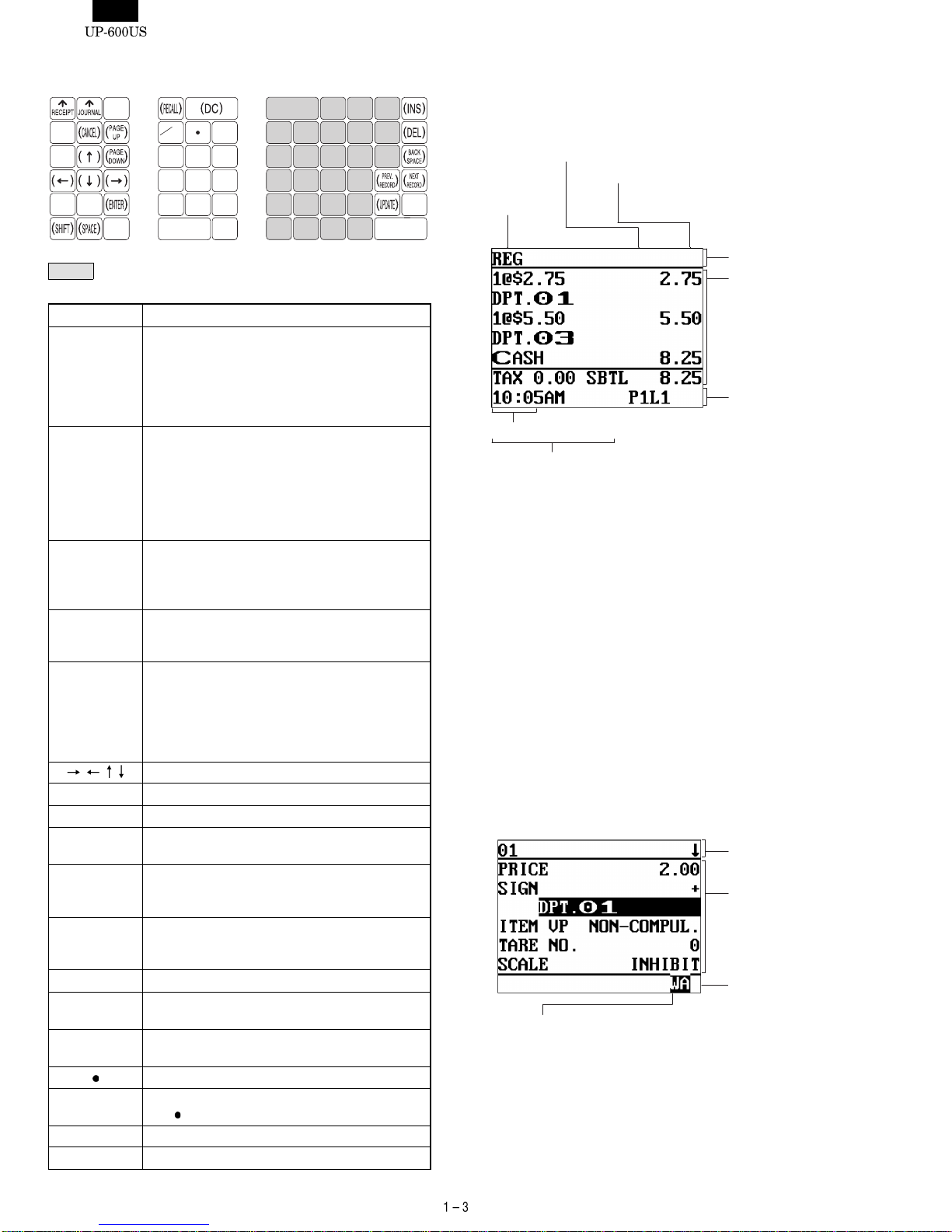
3. DISPLAY
1) OPERATOR DISPLAY
•Screen example 1 (REG mode)
Price level shift indicator
(P1-P6) : Shows the PLU/UPC price level
currently selected.
PLU level shift indicator
(L1-L5) : Shows the PLU level currently se-
lected.
Receipt shift indicator (r) : Shows the receipt shift status.
Stock alarm indicator ( ! ) : Appears when the stock of the PLU
which you entered is zero, negative
or reaches the minimum stock.
Electronic message indi-
cator (M) : Appears when an electronic mail is
received. (Status 1 area)
Receipt ON/OFF status in-
dicator (R) : Appears when the receipt ON-OFF
function signs OFF.
Sentinel mark (X) : Appears in the lower right corner of
the screen when the cash in drawer
exceeds a programmed sentinel
amount.
The sentinel check is performed for
the total cash in drawer.
•Screen example 2 (PGM mode)
SBTL
7
4
1
000
CA/AT
2
56
89
3
@
FOR
CL
E
D
C
B
A
J
I
H
G
FKQ
PV
U
Z
Y
X
O
N
M
L
T
S
R
W
Scroll guidance:
Server code
Mode name
Status area 1:
Time
Status area 2:
Numeric entry
When a transaction information
occupies more than 5 lines, scroll
key(s) appears to indicate you can
scroll to the direction.
Sales information
area:
Sales information
you have just entered
such as items and
prices will appear
between 2nd line and
6th line.
Total is always appear
at 7th line.
Programming item
information area
Programming area:
Programmable items
are listed.
Double-size character mode
indicator (W):
Appears when the double-size
character mode is
selected during text programming.
Caps lock indicator
(A/a):
The upper-case letter “A”
appears when caps lock is on,
and the lower-case letter “a”
appears when caps lock is off
during text programming.

Screen save mode
When you want to save the electric power or save the display’s life,
use the screen save function. This function can turn the LCD off when
a server does not operate the POS terminal for an extended period of
time. You can program the time for which your POS terminal should
keep the normal status (in which the backlight is "ON") before it goes
into the screen save mode.
To go back to the normal mode, press any key.
Device type LCD display
Dot format 320(W) x 240(H) Full dot
Dot size 0.24 (W) x 0.21 (H) mm
Dot space 0.02 mm
Dot color White
Back color Dark blue
2) DISPLAY ADJUSTMENT (OPERATION DISPLAY)
You can adjust the contrast of the display by using the contrast
control, and also you can adjust the display angle. Pull up the tab, the
display will head up.
The backlight in the display is a consumable part.
When the LCD display may no longer be adjusted and becomes
darker, you should change the backlight.
3) CUSTOMER DISPLAY (Pop-up-type)
4. KEYS AND SWITCHES
1) MODE SWITCH AND MODE KEYS
The mode switch has these settings:
OFF: This mode locks all register operations.
No change occurs to register data.
OP X/Z: This setting allows cashiers/clerks to take X or Z reports for
their sales information. (This setting may be used only
when your register has been programmed for "OP X/Z
mode available" in the PGM2 mode.)
REG: For entering sales
PGM1: To program those items that need to be changed often:
e.g., unit prices of departments, PLUs or UPCs, and per-
centages
PGM2: To program all PGM1 items and those items that do not
require frequent changes: e.g., date, time, or a variety of
register functions
MGR: For manager’s and submanager’s entries
The manager can use this mode to make entries that are
not permitted to be made by cashiers/servers -for example,
after-transaction voiding and override entry.
X1/Z1: To take the X/Z report for various daily totals
X2/Z2: To take the X/Z report for various periodic (weekly or
monthly) consolidation
2) DRAWER LOCK KEY
This key locks and unlocks the drawer. To lock it, turn 90 degrees
counterclockwise. To unlock it, turn 90 degrees clockwise.
4) PRINTER COVER LOCK KEY
This key locks and unlocks the printer cover. To lock it, turn 90
degrees counterclockwise. To unlock, turn 90 degrees clockwise.
Tab
Contrast control
Turning the control backwards
darkens the display and
turning it forwards lightens the
display.
REG
OP
X / Z
MGR
X
1
/Z
1
X
2
/Z
2
PGM
1
PGM
2
MA
SM
OFF
MA
SM
SRV
• Manager key (MA) • Submanager key (SM)
• Service key (SRV)
OP
• Operator key (OP)
SK1-2

5. PRINTER (DP-750)
1) SPECIFICATIONS
•Part number: DP-750
•No. of stations: 2
•Printing system: Mechanical serial dot
•Direction of printing: Bidirectional
•Printing capacity: Receipt – 24 characters
Journal – 24 characters
Validation – 55 characters (one line only)
•Character size: 1.36 (W) 2.75 (H) mm at 7 7 dots
Print pitch:
Column distance 1.59 mm
Row distance 4.23 mm
•Total number of dots: Receipt – 108 dots/216 positions
Journal – 108 dots/216 positions
Validation – 248 dots/495 positions
•Font: 7 7 dots (including half dot)
Space between characters – 1 dot (2 po-
sitions)
•Distance between dots: 0.353 mm (H) 0.353 mm (W)
•Print speed: Approx. 3.0 lines/sec.
•Paper feed speed: Receipt – Approx. 30 lines/sec.
Journal – Approx. 30 lines/sec.
•Reliability: MCBF – 4 million lines (excluding the
print head)
Head life – 50 million characters (at 4
dots/1 character/1 pin)
•Validation form sensor: Not available
2) PRINTING AREA
Receipt/journal
Validation form
3) PAPER
•Paper roll dimensions: 44.5 0.5mm in width, 83mm in diameter
•Paper quality: Journal/ Receipt
Bond paper (paper thickness: 0.06 to
0.09mm, paper weight: 52.3 to 64g/m2)
Validation form
Thickness: 0.07 to 0.14mm
Size:130mm or more (W)
70mm or more (H)
4) INKING
•Ink supply system: Ink ribbon
•Form: Cartridge/Endless ribbon
•Specification: Material – Nylon
•Ribbon life: Approx. 6 million characters
•Print color: Purple
5) LOGO STAMP : None
6) CUTTER
•Method: Manual
6. DRAWER
1) SPECIFICATION
(1) Drawer box and drawer
Model name SK-460
Size 445 (W) x 464 (L) x 118 (H)
Color GRAY 368
Material Metal
Bell —
Release lever Standard equipment; Front key
Drawer open sensor Standard equipment
2) MONEY CASE
U version A version
Separation from the drawer
Allowed Allowed Allowed
Separation of the coin
compartments from the money case Disallowed Disallowed
Bill separator No Standard (1 pcs)
Number of compartments 7B/5C 4B/8C
3) LOCK
Location of the lock Front
Method of locking
and unlocking Locking: Insert the drawer lock key into
the lock and turn it 90 degrees
counterclockwise.
Unlocking: Insert the drawer lock key into
the lock and turn it 90 degrees
clockwise.
Key No. SK1-2
87.08
44.5± 0.5
RECEIPT JOURNAL
Unit : mm
37.87
44.5± 0.5
3.56 3.56 3.56 37.87
4.2
3.56
Fig. 5-1
70
130
87.0 (PRINT AREA)
20
22
Unit : mm
Fig. 5-2
Bill separator
A version : 4B/8CU version : 7B/5C

7. RS232 INTERFACE
This machine has two RS232 standard ports for communication to PC, Hand scanner (ER-A6HS1) and etc.
1) PORT 1 (CH1) (CN402)
Connector type: D-SUB 9pin
Data rate: max. 38,400 bps
2) PORT2 (CH2) (CN403)
Connector type: Modular jack RJ45 8pin
Data rate: max. 115,200 bps
3) OPTIONAL DEVICES THAT CAN BE CONNECTED
Standard port Option port (ER-A5RS)
Port No. Port1: CH1 Port2: CH2 Port3: Port4:
Type D-SUB 9pin Moduler RJ45 D-SUB 9pin D-SUB 9pin
CI/+5V selectable –––
ER-A6HS1 (+5V necessary) –––
Scanner (+5V not necessary)
Modem –
PC
Printer, Scale
POS utility, 02fd.exe – ––
The ER-A6HS1 cannot be connected to port 2, 3 and 4 because it
requires +5V.
The modem cannot be connected to port 2 because it uses a
different signal line.
For the modular RJ45 to D-Sub 9pin conversion cable, see the
following.
1
2
3
4
5
6
7
8
9
/CD
RD
SD
/ER
GND
/DR
/RS
/CS
/CI
VCC(+5V)
S401
1
2
3
4
5
6
7
8
/RS
/ER
SD
GND
RD
/DR
/CS
CI
CD
S404
S403
VCC
(+5V)
GND
CD CI
S404
7
4
3
1
5
2
6
8
9
/RS
/ER
SD
/CD
GND
RD
/RS
/CS
/CI
1
2
3
4
5
6
7
8
/RS
/ER
SD
GND
RD
/DR
/CS (Open)
Moduler RJ45 D-sub 9pin
VCC
(+5V)
S403
GND


2. SALES OPTIONS
No. CLASSIFICATION COMPONENT NAME MODEL NAME REMARK
1 Memory Expansion RAM board UP-S02MB 2M bytes PS-RAM board
UP-S04MB 4M bytes PS-RAM board
2 Display Remote display (Pole type) UP-P16DP 11-Dig.7-Seg. + 16-Dig.Dot
3 Drawer Remote drawer ER-03DW 7B/5C coin case
ER-04DW 5B/5C coin case
4 On-line function RS232 I/F board ER-A5RS 2 ports RS232 I/F
5 Card reader MCR (Magnetic Card Reader) UP-E13MR ISO Type 1 : 3 stripe card
6 Scanner Bar code hand scanner ER-A6HS1
7 Expansion key kit Key top kit ER-11KT7 1 1 Key top kit
ER-12KT7 1 2 Key top kit
ER-22KT7 2 2 Key top kit
Dummy key kit ER-11DK7G 1 1 Dummy key kit
ER-51DK7G 5 1 Dummy key kit
3. LOCAL PURCHASE OPTIONS
No. COMPONENT NAME MODEL NAME REMARK
1 External printers TM-T88/85, TM-T88 (2), TM-T80
TM-U200, TM-300
2 Slip printer TM-295
3ScaleI/F
4 Coin dispenser
5 Color kitchen monitor
6 CAT terminal
1: Please consult with your Sharp regional sales manager.
4. SERVICE OPTIONS
No. NAME PARTS CODE PRICE DESCRIPTION
1 Mode key grip cover AX For MA key only
2 Drip proof mode switch cover BA
3 Drip proof keyboard cover BF
4 Text preset keyboard cover BH
5. SERVICE TOOLS
No. NAME PARTS CODE PRICE DESCRIPTION
1 Service key AF
2 RS232 Loop Back Connector BC For RS232 D-SUB 9pin connector
3 RS232 modular Loop Back Connector BC For RS232 RJ45 Modular jack connector
4 Expansion PWB for option board BU For ER-A5RS
5 MCR test card BL For UP-E13MR
6 Key top remover AX
7 Key top inst. Jig BB For 2 2 key top
6. SUPPLIES
No. NAME PARTS CODE PRICE DESCRIPTION
1 Roll paper AR 5 roll/pack
2 Ink libbon AZ Purple
>>>>> USE FONT <<<<<
Helvetica/ Helvetica-Condensed/ Century-Schoolbook/ Symbol & OriginalFonts: (RingWorld2/RingFont2/Pa
Symbol/PartsCod)
- - - - - - - - - - - - - - - - - - - - - - - - - - - - - - - - - - - - - - - - - - - - - - - - - - - - - - -

7. HOW TO USE SERVICE TOOLS
1) EXPANSION PWB : CKOG-6708RCZZ
•External view
Purpose 1 : Used for servicing and repairing of options (such as the
ER-A5RS) which are connected with the main body op-
tion connector.
[Procedure 1]
Use an insulator base as shown in the shaded section when perform-
ing servicing.
To check the option I/F PWB from the solder side, connect the I/F
PWB to OPTCN2. To check from the parts side, connect to OPTCN3.
(Note) The option I/F PWB should be held horizontally so that no
excessive stress is applied to connecting section .
[Procedure 2]
Put a string between the pop up and the option PWB. Adjust the
length of the string so that the CKOG-6708RCZZ and the option PWB
are not binding. Once verified, then you may proceed with performing
service.
2) MCR TEST CARD : UKOG-2357RCZZ
•Used when executing the diagnostics of the UP-E13MR.
•External view
UP-600
Main PWB
Expansion PWB
(CKOG-6708RCZZ) ER-A5RS
PWB
Loop back connectors
UKOG-6705RCZZ
Base
A
UP-600
Main PWB
Expansion PWB
(CKOG-6708RCZZ)
ER-A5RS
PWB
Control ROM
Pop up
String
Loop back connectors
UKOG-6705RCZZ

CHAPTER 3. SERVICE PRECAUTION
1. IPL (Initial Program Loading) FUNCTION
1) INTRODUCTION
The application software of the UP-600 is written in the flash ROM.
In the following cases, writing of the application software into the flash
ROM is required.
•When the flash ROM is replaced with a new one. The service part
flash ROM does not include the application software in it.
•When IPL writing is required because of a change in the software.
The service part of the main PWB unit includes the flash ROM with
the application software written in it, and there is no need for
writing the application software when replacing the main PWB unit.
2) IPL PROCEDURE
There are two ways for the IPL procedures.
•IPL from P-ROM
•IPL from PC communication (Please refer to the next section)
The detailed descriptions on the above procedures are given below.
3) IPL FROM P-ROM
Master ROM-1 : VHI27801RAS1A
Master ROM-2 : VHI27801RAT1A
Before installation, turn off the power switch on the UP-600 and un-
plug the AC cord from the AC outlet.
1. Insert a screwdriver into the slit on the right side of the lower
cabinet to remove the option RAM case.
2. IPL switch (SW301) on the IPL ROM PWB: Set the IPL switch
(SW301) to the ON position.
3. Install the ROMs into the IC sockets on the IPL ROM PWB as
shown below.
4. Place the mode key to any position except OFF or SRV’.
5. Turn on the power switch of the UP-600.
6. The following display is shown and the IPL procedure is started.
When the procedure is completed, the message of "Completed"
is shown.
7. Turn off the power switch of UP-600.
8. Remove to the ROMs from the IPL ROM PWB.
9. IPL switch (SW301) on the IPL ROM PWB: Set the IPL switch
(SW301) to the OFF position.
10. Perform one of the master reset procedures.
ROM1 ROM2
ROM1 ROM2
on off
SW301
IPL from PROM
Version check…
Erase …
IPL write start
26 27 28 29 2A 2B
2C 2D 2E 2F 30 31
38 39 3A 3B 3C 3D
3E 3F
Verify … IPL write completed
32 33 34 35 36 37
Completed.

2. UP-600 UTILITY TOOLS
1) OUTLINE
This Specification document describes the explanation about "POSU-
TILITYTOOL.EXE and "02FD.EXE".
"POSUTILITYTOOL.EXE"and "02FD.EXE" works on Windows 95/98
of PC and they have the following
Functions by connecting UP-600 with RS232.
POSUTILITYTOOL.EXE : IPL of UP-600 Program Object
02FD.EXE : All RAM Data Upload/Download
(PC software tool instead of the cur-
rent ER-02FD.)
2) CONNECTION
PC and UP-600 are connected by RS232.
Connect the CH2 port of the UP-600 to the RS-232 interface of the
PC.
RS232 Cable Connecting:
3) PROCEDURE
3) -1. POS UTILITY
No Procedure on P.C. side No Procedure on UP-600 side
1 Install the "POSUTILITYTOOL.EXE" on the P.C.
2 Turn OFF the power.
3 Select "IPL Mode".
Set the "IPL Switch" (SW302) of the UP-600 to "ON".
4 Turn ON the power.
5 Starting of "IPL Mode".
The UP-600 displays
"IPL from Serial I/O"
6 Connect the P.C. and the UP-600 (CH2) via RS232. (Fig 1)
UP-600:CH2
PC
D-SUB 9pin - D-SUB 9pin
cable D-SUB 9pin - modular RJ-45
conversion cable
(Open)
CD
D-sub 9pin
1
2
3
4
5
6
7
8
9
/CD
RD
SD
/ER
GND
/DR
/RS
/CS
/CI
RD
SD
/ER
GND
/DR
/RS
/CS
1
2
3
4
5
6
7
8
1
2
3
4
5
6
7
8
9
1
2
3
4
5
6
7
8
9
RD
SD
GND
CI
GND
S404
VCC
(+5V)
[UP-600]
Moduler RJ45
[PC]
D-sub 9pin
S403
on off
SW302
on off
IPL from Serial I/O
>>>>> USE FONT <<<<<
Helvetica/ Helvetica-Condensed/ Century-Schoolbook/ Symbol & OriginalFonts: (RingWorld2/RingFont2/Pa
Symbol/PartsCod)
- - - - - - - - - - - - - - - - - - - - - - - - - - - - - - - - - - - - - - - - - - - - - - - - - - - - - - -

No Procedure on P.C. side No Procedure on UP-600 side
7 Execute the "POSUTILITUTOOL.EXE" on the P.C.
*Please close all other applications while using this utility.
8 Select the ROM object Files by clicking the "Add Files.." button.
9 Push the "SEND" button.
Program data is sent to the UP-600 automatically. 9Program data is received from the P.C. automatically.
The UP-600 displays.
10 When data sending is completed,
the initial Window is shown after "Complete" window. 10 The UP-600 displays
"Completed."
11 Turn OFF the power.
12 Select "Normal Mode".
Set the "IPL switch" to "OFF".
(Ref. Hardware manual)
13 Execute the "Service Reset" on UP-600.
IPL from Serial I/O
Connected IRDA 115200
21 22 23 24 25 26 27 28
IPL from Serial I/O
Connected IRDA 115200
21 22 23 24 25 26 27 28
29 2A 2B 2C 2D 2E 2F
Completed.
IPL from Serial I/O
Connected IRDA 115200
30 31 32 33 34 35 36 37
38 39 3A 3B 3C 3D 3E 3F
Completed.

3) -2. 02FD
No Procedure on P.C. side No Procedure on UP-600 side
1 Install the "02FD.EXE" on the P.C.
ALL RAM Data UpLoad : Go to "2"
ALL RAM Data DownLoad : Go to "9"
2 ALL RAM Data UpLoad
Connect the P.C. and the UP-600 (CH2) via RS232. (Fig 1) 2 Enter the SRV mode.
Select " 2 SETTING ".
Select " 14 BACKUP SEND"
3 The UP-600 displays
4 Execute the "02FD.EXE" on the P.C.
*Please close all other applications while using this utility.
5 Set the Communication method by pushing the "Setting" Button.
Push the "OK" Button.
6 Push the "Receive Start" Button.
And Select the Receiving File.
7 Communication starts. 7 Push CA/AT key. The UP-600 displays
8 The UpLoad is completed.
The initial Window is shown.
Push the "Exit" Button.
8 The UpLoad is completed.
The SETTING menu is shown.
9 ALL RAM Data UpLoad
Connect the P.C. and the UP-600 (CH2) via RS232. (Fig 1) 9 Enter the SRV mode.
Select " 2 SETTING".
Select " 15 BACKUP RECEIVE"
10 The UP-600 displays
Push the CA/AT key.
SEND DATA ALL RAM
SPEED PROGRAMMED SPEED
BACKUP SEND
SENDING 00000
BACKUP RECEIVE
SPEED PROGRAMMED SPEED

No Procedure on P.C. side No Procedure on UP-600 side
11 Execute the "02FD.EXE" on the P.C.
*Please close all other applications while using this utility.
12 Set the Communication method by pushing the "Setting" Button.
Push The "OK" Button.
13 Push the "Transmit Start" Button.
And Select the Sending File.
14 Communication starts. 14 The UP-600 displays
15 The DownLoad is completed.
The initial Window is shown.
Push the "Exit" Button.
15 The DownLoad is completed.
The SETTING menu is shown.
16 Execute the " Service Reset " on the UP-600
3. NOTE FOR HANDLING OF LCD
•The LCD elements are made of glass. Use extreme care when
handling the LCD.
Any strong shock applied to the LCD can cause damage.
•If the LCD element is broken and the liquid has leaked, do not
come in contact with it. If the liquid is attached to your skin or cloth,
immediately clean with soap.
•Use the unit under the rated conditions to prevent against damage.
•Be careful not to drop water or other liquids on the display surface.
•The reflection plate and the polarizing plate are easily scratched.
Be careful not to touch them with hard objects such as glass,
tweezers, etc. Never hit, push, or rub the surface with hard objects.
•When installing the unit, be careful not to apply stress to the LCD
module. If excessive stress is applied, abnormal display or uneven
color may result.
RECEIVING 00000

CHAPTER 4. SRV. RESET AND MASTER RESET
The SRV key is used for operating in the SRV mode.
1. SRV. RESET (Program Loop Reset)
Procedure
•Method 1
1) Turn off the AC switch.
2) Set the mode switch to (SRV’) position.
3) Turn on the AC switch.
4) Turn to (SRV) position from (SRV’) position.
•Method 2
1) Set the mode switch to PGM2 position.
2) Turn off the AC switch.
3) While holding down the JOURNAL FEED and RECEIPT FEED
keys, turn on the AC switch.
Note: When disassembling and reassembling always power up us-
ing method 1 only. Method 2 will not reset the CKDC9.
Note: SRV programming job#926-B must be set to a "4" to allow the
PGM program loop reset.
PRG. RESET
2. MASTER RESET (All memory clear)
There are three possible methods to perform a master reset.
MRS-1 (Master resetting 1)
Used to clear all memory contents and return the machine back to its
initial settings.
Returns the keyboard to the default layout.
Procedure
1) Turn off the AC switch.
2) Set the MODE switch to the (SRV’) position.
3) Turn on the AC switch.
4) While holding down the JOURNAL FEED key, turn to the
(SRV) position from the (SRV’) position.
MRS-2 (Master resetting 2)
Used to clear all memory and keyboard contents.
This reset returns all programming back to defaults. The keyboard
must be entered by hand.
This reset is used if an application needs a different keyboard layout
other than that supplied by a normal MRS-1.
Procedure
1) Turn off the AC switch.
2) Set the MODE switch to the (SRV’) position.
3) Turn on the AC switch.
4) While holding down the JOURNAL FEED and RECEIPT FEED
keys, turn to the (SRV) position from the (SRV’) position.
5) Key position assignment:
After the execution of a MRS-2, only the RECEIPT FEED and
JOURNAL FEED keys can remain effective on key assignment.
Any key can be assigned on any key position on the main key-
board.
[key setup procedure]
MASTER RESET
NOTES:
*1: When the 0 key is pressed, the key of the key number on the
display is disabled.
*2: Push the key on the position to be assigned. With this, the key of
the key number on the display is assigned to that key position.
*3: When relocating the keyboard, the PGM 1/2 modes use the
standard key layout.
Key
No. Key
name Key
No. Key
name Key
No. Key
name
001 011 021
002 012 022
003 013 023
004 014
005 015
006 016
007 017
008 018
009 019
010 020
MRS-2 executed Key position set Free key
Disable
Free key setup
complete.
*2
*1
0
0

MRS-3 (Master resetting 3)
Master resetting 3 requires the entry of Serial No. data in addition to
Master resetting 2.
After completion of the MRS-3, the following operations and program-
ming will be inhibited.
1. GT programming.
2. All memory download via RS-232.
3. GT resets with Z report. (Z report can be made, but the GT will not
be reset.)
Procedure
1) Turn off the AC switch.
2) Set the reset switch to the "SRV" position.
3) Turn on the AC switch.
4) While holding down the JOURNAL FEED key and MRS-3 key,
turn to the (SRV) position from the (SRV’) position.
MRS-3 key : UP-600=[CANCEL] key
UP-700=[PLU72] key
5) The product serial No. input window is displayed as shown
below.
DISPLAY:
Enter the product serial No. of this POS and enter the [CA/AT]
key.
6) Key position assignment:
After the execution of MRS-3, only the RECEIPT FEED and
JOURNAL FEED keys can remain effective on key assignment.
Any key can be assigned on any key position on the main key-
board.
[key setup procedure]
MASTER RESET
NOTES:
*1: When the 0 key is pressed, the key of the key number on the
display is disabled.
*2: Push the key on the position to be assigned. With this, the key of
the key number on the display is assigned to that key position.
*3: When relocating the keyboard, the PGM 1/2 modes the use
standard key layout.
Key
No. Key
name Key
No. Key
name Key
No. Key
name
001 011 021
002 012 022
003 013 023
004 014
005 015
006 016
007 017
008 018
009 019
010 020
SERIAL No. 00000000
MRS-2 executed Key position set Free key
Disable
Free key setup
complete.
*2
*1
0
0
>>>>> USE FONT <<<<<
Helvetica/ Helvetica-Condensed/ Century-Schoolbook/ Symbol & OriginalFonts: (RingWorld2/RingFont2/Pa
Symbol/PartsCod)
- - - - - - - - - - - - - - - - - - - - - - - - - - - - - - - - - - - - - - - - - - - - - - - - - - - - - - -

CHAPTER 5. DIAGNOSTICS SPECIFICATIONS
1. GENERAL DESCRIPTION
This Diag Program consists of a number of Diag. programs for the
UP-600, which facilitate the PWB check, process check and the op-
eration check of the system during servicing.
The Service Diag. programs are all contained in the standard ROM.
2. SYSTEM COMPOSITION
UP-600 only
3. DIAG.
Starting the Diag. Program
The Diag. Program is written on the external ROM, which is executed
by the CPU (H8/510) and runs on the following conditions:
The logic power supply is normal.
(+5V, VCKDC, POFF, +24V)
Both the I/O pins of the CPU and the CPU internal logic are
normal, and the CKDC9 and MPCA9, system bus, and standard
ROM/RAM are normal.
1) EXECUTING DIAG PROGRAM
To start the Diag. Program, enter the SRV mode. Select the option
item DIAGNOSTICS from the MENU using the cursor keys and press
the ENTER key.
The DIAG. MAIN MENU appears on the screen as shown below. The
cursor is displayed in reverse video and can be moved using the
up/down arrow keys. Move the cursor to the menu item you want and
press the ENTER key to execute the corresponding Diag. program.
When each Diag. program is completed, the screen returns to the
DIAG. MAIN MENU. Press the CANCEL key to exit the Diag. Pro-
gram and the screen returns to the SRV mode menu screen.
2) RAM & ROM & SSP DIAGNOSITCS
This program tests the standard RAM, expanded RAM, standard and
service ROMs, and SSp circuit. RAM&ROM&SSP is selected on the
MAIN MENU, the following sub-menu screen appears. The cursor
shown in reverse video can be moved using the up/down arrow keys.
Move the cursor to the menu item you want and press the ENTER
key to execute the corresponding program. Press the CANCEL key to
return the screen to this submenu.
2)-1. Standard RAM check
Checking
The program performs the following checks on the standard
512KB of RAM. Data in memory remains unchanged before and
after the checks.
The following operations are performed for the memory addresses
to be checked (780000H - 7FFFFFH).
PASS1 : Save data in memory
PASS2 : Write data "0000H"
PASS3 : Read and compare data "0000H" and write data "5555H".
PASS4 : Read and compare data "5555H" and write data "AAAAH"
PASS5 : Read and compare data "AAAAH"
PASS6 : Return data into memory
If any comparison is not normal during the check sequence from
PASS 1 through 6, the error message appears.
If any error is not found up to the final address, the sequence
ends normally.
Then, another round of address checks is carried out using the
above check sequence
If an error occurs, the error message appears and the check
stops. The read/write of the address where the error occurs is
repeated.
Check point address = 780000H, 780001H
780002H, 780004H
780008H, 780010H
780020H, 780040H
780080H, 780100H
780200H, 780400H
780800H, 781000H
782000H, 784000H
788000H, 790000H
7A0000H, 7C0000H
UP-600
Fig 2-1. Service
UP-600 DIAG V1.0A
PRODUCT&TEST
RAM&ROM&SSP
CLOCK&KEY&SWITCH
SERIAL I/O
DISPLAY&PRINTER
MCR&DRAWER
TCP/IP
SSP Check
Service ROM Check
Standard ROM Check
UP-S02MB Check
UP-S04MB Check
Standard RAM Check
RAM&ROM&SSP DIAG

Display
The capacity checked is displayed in units of 64KB.
The error address and bit are displayed only when an error occurs
(They are not displayed if there is no error.)
How to exit the program
You can exit the program by pressing the CANCEL key after the
results are displayed.
2)-2. UP-S02MB Check
Checking
The program checks for the presence of the UP-S02MB in the
following procedure.
Data in memory remains unchanged before and after checking.
i. Write 55AAH in 9FFFFEH.
ii. Read 9FFFFEH and compare the data with 55AAH. If both
data are correct and BFFFFEH is the same as 55AAH, the
following tests are performed. If not correct, the message
"0KB: ERROR!!" appears and checking ends.
The following checks are performed on the UP-S02MB.
The following operations are performed for the address space to
be checked (800000H - 9FFFFFH).
PASS1 : Save data in memory.
PASS2 : Write data "0000H".
PASS3 : Read and compare data "0000H" and write data "5555H".
PASS4 : Read and compare data "5555H" and write data "AAAAH".
PASS5 : Read and compare data "AAAAH".
PASS6 : Return data into memory.
If any comparison is not normal during the check sequence from
PASS 1 through 6, the error message appears.
If any error is not found up to the final address, the sequence
ends normally.
Then, another round of address checks is carried out using the
above check sequence.
If an error occurs, the error message appears and the checking
stops. The read/write of the address where the error occurs is
repeated.
Check point address = 800000H, 800001H
800002H, 800004H
800008H, 800010H
800020H, 800040H
800080H, 800100H
800200H, 800400H
800800H, 801000H
802000H, 804000H
808000H, 810000H
820000H, 840000H
880000H, 900000H
Display
The capacity checked is displayed in units of 64KB.
The error address and bit are displayed only when an error occurs
(They are not displayed if there is no error.)
How to exit the program
You can exit the program by pressing the CANCEL key after the
results are displayed..
2)-3. UP-S04MB Check
Checking
The program checks for the presence of the UP-S04MB in the
following procedure. Data in memory remains unchanged before
and after checking.
i. After writing 55AAH in BFFFFEH, write AA55H in 9FFFFEH.
ii. Read BFFFFEH and compare the data with 55AAH. Data in
BFFFEH is correct, the following checks are performed. Data
read is AA55H, the message "UP-S02MB!!" appears and the
check ends. If the data read is not either 55AAH or AA55H, the
message "0KB:ERROR!!" appears and the check ends.
The following checks are performed on the UP-S04MB.
The following operations are performed for the address space to
be checked (800000H - BFFFFFH).
PASS1 : Save data in memory.
PASS2 : Write data "0000H".
PASS3 : Read and compare data "0000H" and write data "5555H".
PASS4 : Read and compare data "5555H" and write data "AAAAH".
PASS5 : Read and compare data "AAAAH".
PASS6 : Return data into memory.
If any comparison is not normal during the check sequence from
PASS 1 through 6, the error message appears.
If any error is not found up to the final address, the sequence
ends normally.
Then, another round of address checks is carried out in the above
check sequence.
If an error occurs, the error message appears and the checking
stops. The read/write of the address where the error occurs is
repeated.
Check point address = 800000H, 800001H
800002H, 800004H
800008H, 800010H
800020H, 800040H
800080H, 800100H
800200H, 800400H
800800H, 801000H
802000H, 804000H
808000H, 810000H
820000H, 840000H
880000H, 900000H
A00000H
Read:XXXXH
Write:XXXXH
Error:XXXXXXH
512KB:PASS!!(or ERROR!!)
Standard RAM Check
Read:XXXXH
Write:XXXXH
Error:XXXXXXH
2048KB:PASS!!(or ERROR!!)
UP-S02MB Check
>>>>> USE FONT <<<<<
Helvetica/ Helvetica-Condensed/ Century-Schoolbook/ Symbol & OriginalFonts: (RingWorld2/RingFont2/Pa
Symbol/PartsCod)
- - - - - - - - - - - - - - - - - - - - - - - - - - - - - - - - - - - - - - - - - - - - - - - - - - - - - - -

Display
The capacity checked is displayed in units of 64KB.
The error address and bit are displayed only when an error occurs
(They are not displayed if there is no error.)
How to exit the program
You can exit the program by pressing the CANCEL key after the
results are displayed.
2)-4. Standard ROM Check
Checking
The standard ROM area (200000H - 3FFFFFH) is added in units
of bytes. When the lowest 2 digits of the result is 20H, it is re-
garded as normal.
In addition, the ROM version and model name code stored in the
addresses 31FFE0H - 31FFFFH where the ROM version and
checksum correction data are stored are displayed. Data (ASCII)
is stored in the following formats:
31FFE0H~31FFEFH : Model name CODE (Example: "UP-600",
to be displayed until DATA becomes 00H.)
31FFF0H~31FFF9H : 27801R****(****=PROGRAM VERSION)
31FFFAH~31FFFBH : BLOCK NO.("20"~"3F")
31FFFCH : TERMINATOR ("=")
31FFFDH~31FFFEH : BLOCK VERSION (Example: "00")
31FFFFH : CHECK SUM correction DATA
FLASH ROM used as the standard ROM has 64K-byte-unit re-
write BLOCKs. To perform VERSION management in the BLOCK
unit, these BLOCKs have the same 16 byte organization as those
after the previous 31FFF0H and arranged every 64KBYTE. At this
time, the checksum for each BLOCK is corrected to be 01H so
that the entire 2MBYTE become a total of 20H.
Regarding the display of the PROGRAM VERSION, the FLASH
write MASTER EPROM has 8Mbits chips to allow management of
the block units of the chip. The PROGRAM VERSION stored in
blocks at 21H and 31H are displayed.
0 PAGE (BLOCK) where the IPL is stored, displays the PRO-
GRAM VERSION of the IPL to make it possible to manage individ-
ual programs.
Display
The capacity checked is displayed in units of 64KB.
JOURNAL print
How to exit the program
You can exit the program by pressing the CANCEL key after the
result of checking is displayed.
2)-5. SERVICE ROM Check
Checking
The SERVICE ROM area composed of two EPROMs (D00000H -
EFFFFFH) is added in units of bytes for each chip. If the lowest 2
digits are 10H, it is regarded as normal.
In addition, the ROM version and model name code stored in the
addresses D1FFE0H - D1FFFFH where the ROM version and
checksum correction data are stored are displayed. Data (ASCII)
is stored in the following formats:
D1FFE0H~D1FFEFH : Model name CODE(Example: "UP-600",
to be displayed until data is 00H.)
D1FFF0H~D1FFF9H : 27801R****(****=PROGRAM VERSION)
D1FFFAH~D1FFFBH : BLOCK NO.("20"~"2F")
D1FFFCH : TERMINATOR("=")
D1FFFDH~D1FFFEH : BLOCK VERSION(Example:"00")
D1FFFFH : CHECK SUM correction DATA
This SERVICE ROM is used to write data into FLASH ROM and if
any error occurs during rewriting of the FLASH ROM, it is not
possible to resume operations. Its configuration is the same as the
standard ROM.
0 PAGE (BLOCK) where the IPL is stored displays the PRO-
GRAM VERSION of the IPL to make it possible to manage individ-
ual programs.
Display
The capacity checked is displayed in units of 64KB.
JOURNAL print
How to exit the program
You can exit the program by pressing the CANCEL key after the
result of checking is displayed.
Read:XXXXH
Write:XXXXH
Error:XXXXXXH
4096KB:PASS!!(or ERROR!!)
UP-S04MB Check
IPL:**
27801R****
APL: 27801R****
PASS!!(or ERROR!!)
Service ROM Check
3C=** 3D=** 3E=** 3F=**
. . . . . . . . . . .
24=** 25=** 26=** 27=**
20=** 21=** 22=** 23=**
BLOCK Version.
IPL:**
27801R****
APL: 27801R****
ROM2:PASS!!(or ERROR!!)
ROM1:PASS!!(or ERROR!!)
Service ROM Check
3C=** 3D=** 3E=** 3F=**
. . . . . . . . . . .
24=** 25=** 26=** 27=**
20=** 21=** 22=** 23=**
BLOCK Version.
Other manuals for UP-600
9
This manual suits for next models
2
Table of contents
Other Sharp Cash Register manuals

Sharp
Sharp XE-A303 User manual

Sharp
Sharp ER-A310 User manual

Sharp
Sharp XE-A101 User manual

Sharp
Sharp XE-A307 User manual

Sharp
Sharp XE-A201 Parts list manual

Sharp
Sharp XEA102 - Cash Register User manual

Sharp
Sharp ER-A247 User manual

Sharp
Sharp XE-A407 User manual

Sharp
Sharp ER-A247 User manual

Sharp
Sharp ER-A610 Owner's manual

Sharp
Sharp ER-A570 User manual

Sharp
Sharp ER-2386S User manual

Sharp
Sharp ER-3550 User manual

Sharp
Sharp XE-A101 User manual

Sharp
Sharp er-3100 User manual

Sharp
Sharp UP-600 User manual

Sharp
Sharp XE-A406 Parts list manual

Sharp
Sharp UP-600 User manual

Sharp
Sharp UP-820N User manual

Sharp
Sharp ER-A170 User manual