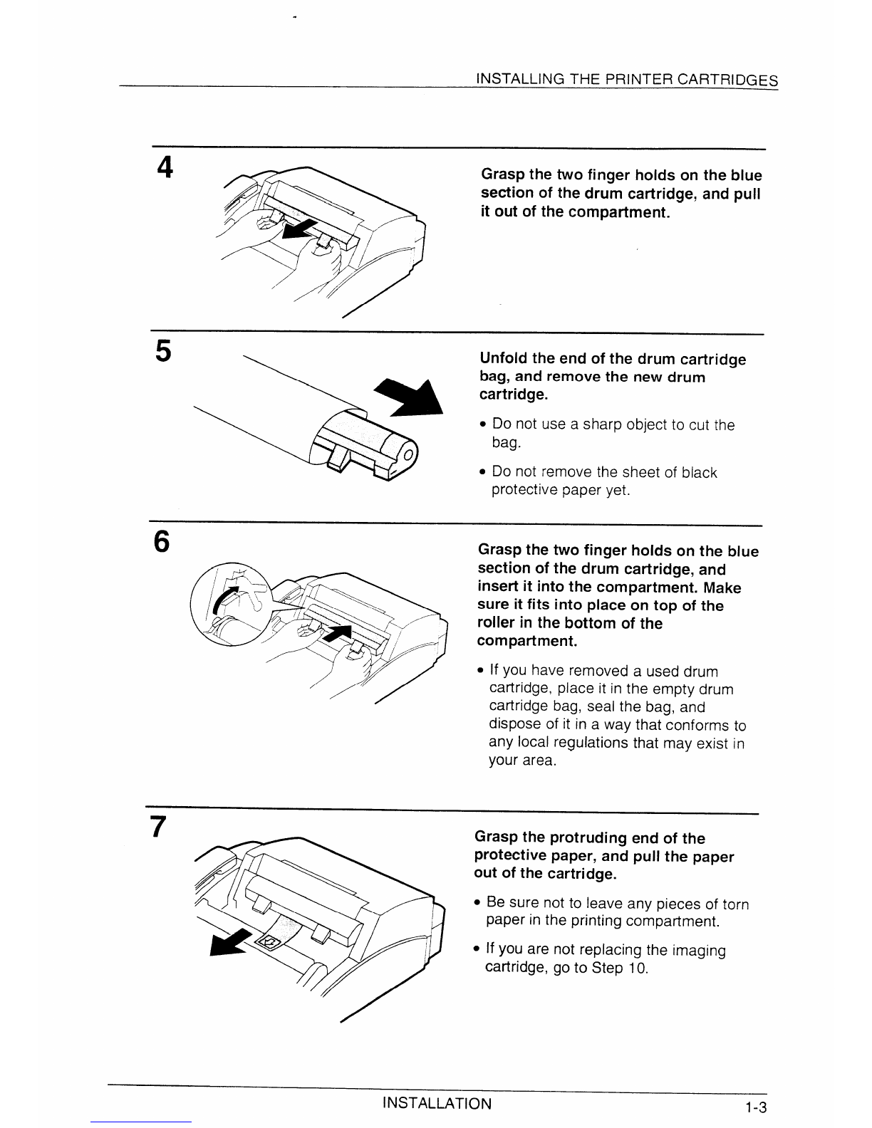
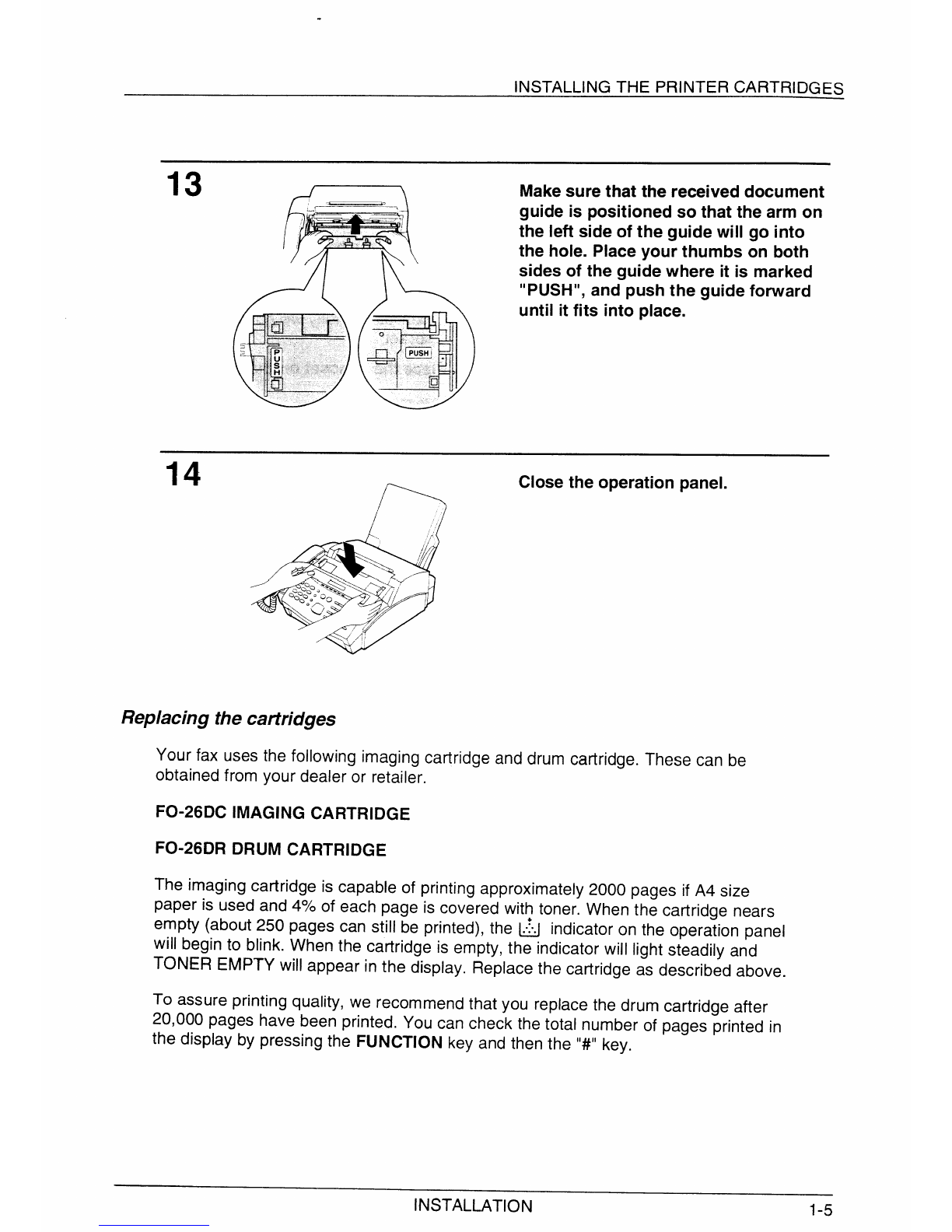
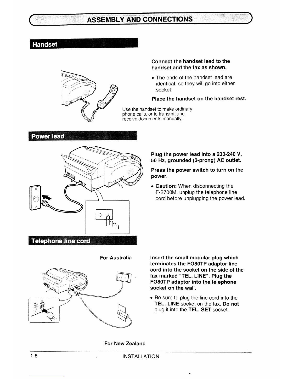
Sharp F-2700M User manual

MFACSIMILE
OPERATION MANUAL
1. INSTALLATION
2. INITIAL SETTINGS
3. PRINTING SETUP
4. BASIC OPERATIONS
5. ANSWERING MACHINE HOOK-UP
6. SPECIAL FUNCTIONS
7. OPTIONAL SETTINGS
8. PRINTING OUT REPORTS AND LISTS
9. MAINTENANCE
10. TROUBLESHOOTING
SPECIFICATIONS
QUICK REFERENCE GUIDE
INDEX

WARNING —AUSTEL Regulations state that no unauthorised changes or modifications to this
equipment are permitted.
Note: Complies with the AUSTEL standards TS 002-1990 regarding Emission of Electro-
magnetic interference.
These limits are designed to provide reasonable protection against interference in an
installation. This equipment generates, uses and can radiate radio frequency energy and, if
not installed and used inaccordance with the instructions, may cause interference. However,
there is no guarantee that interference will not occur in aparticular installation. If this
equipment does cause interference to radio or television reception, which can be determined
by turning the equipment off and on, the user is encouraged to try to correct the interference
by one or more of the following measures:
—Reorient or relocate the receiving antenna.
—Increase the separation between the equipment and the receiver.
—Connect the equipment into an outlet on a circuit different from that to which the receiver
is connected.
—Consult the dealer or an experienced radio/TV technician for help.
FOR YOUR RECORDS
Please record the model number and serial number below, for easy reference, in
caseof loss or theft. These numbers are located on the rear side of the unit.
Space is also provided for other relevant information.
Model Number
Serial Number
Dateof Purchase
Place of Purchase

‘..
.\
Welcome to the F-2700M, arid thank you for choosing Sharp!
The F-2700M is acombination facsimile and laser printer. In addition to afull range of
fax functions designed to increase the scope and power of your communications, the
F-2700M features fast, high-quality printing of documents created with your computer
software applications.
All printing functions are controlled from easy-to-use graphical controls on your
computer screen. All fax and copying functions are controlled from the operation panel
of the F-2700M. Faxes can be sent while printing is in progress, and if afax is
received during aprinting job, it will be printed immediately, after which the printing job
will resume.
This manual gives you instructions for installing the F-2700M, installing the printer
software in your computer, and performing fax and copying operations. For detailed
information about printing functions, see the Help file on your computer screen which
is included in your printer software.
The F-2700M is designed to operate in Australia and New Zealand only.
If YOUhave any questions or problems which cannot be solved by reading this manual,
please contact your Sharp dealer.
Trademarkacknowledgements
Microsoft, Windows, MS-DOS, Windows NT, Windows 95, and Windows Printing
System are trademarks of Microsoft Corporation in the U.S.A. and other countries.
TrueType is atrademark of Apple Computer, Inc.
IBM, PC/AT, and 0S/2 are trademarks of International Business Machines
Corporation.
Hewlett-Packard, HP, LaserJet, and PCL are trademarks of Hewlett-Packard
Company.
All other trademarks and copyrights are the property of their respective owners.
+Importantsafety information
●
●
●
●
●
●
Never install telephone wiring during alightning storm.
Never install telephone jacks in wet locations unless the jack is specifically designed for
wet locations.
Never touch uninsulated telephone wires or terminals unless the telephone line has
been disconnected at the network interface.
Installing or modifying telephone lines should only be done by an Austel licensed
serviceman.
Do not use atelephone to report agas leak in the vicinity of the leak.
Your fax machine and the telephone system
The Austel Registration Number and Ringer Equivalence Number (REN) for this
equipment are shown on the label on the back of the machine. The telephone
company may require these numbers.
The sum of all Ringer Equivalence Numbers on your telephone line should be three or
less in order to assure proper service from the telephone company.
For your safety, if any of your equipment is not operating properly or should any
physical damage occur to the equipment where internal parts may become exposed,
the equipment should be immediately disconnected from the phone line and then the
power line and returned to aSHARP authorised Service Centre for inspection, repair,
or disposal.
i

1INSTALLATION
UNPACKING . . . . . . . . . . . . . . . . , . “s~. . ~-0. . -~~E•Œ••˜•ìS˜•ØS˜•~“ “ o““-0~. . “’-’
INSTALLING THE PRINTER CARTRIDGES . . . . . , . . . . . ~. , . . ~. . . . . . . , .1-2
ASSEMBLY AND CONNECTIONS . . . . . . . . . . . . . -. . . . . , . . . . -. . . . . . , 1-6
CONNECTING THE INTERFACE CABLE . . . . , . . . , . . . . -.-, . . . . . . . . . . l-lo
LOADING PRINTING PAPER . . . . . . . . . . -. . . , . . . . . . . . . . . , . . . . . -1-1I
2INITIALSE~lNGS
ALOOK AT THE OPERATION PANEL .......
ENTERING YOUR NAME AND FAX NUMBER . . .
ENTERING LE~ERS FOR NAMES . . . . . . . . .
SETTING THE DATE AND TIME . . . . . . . . . . .
SELECTING THE RECEPTION MODE . . . . . . .
DISTINCTIVE RINGING . . . . . . . . . . . . . . .
STORING NUMBERS FOR AUTOMATIC DIALLING
3PRINTINGSETUP
.
—
. . .
.
.
.
.2-1
.2-2
.2-3
.2-5
.2-6
.2-7
.2-8
WINDOWS PRINTING SYSTEM . . . . . . . . . . . . . . . . . . . . . . . . . -. . . . . . .3-1
INSTALLING WINDOWSPRINTING SYSTEM .........................3-2
CHANGING VIRTUAL MEMORY S~lNGS . . . . . . . . . . . . . . . . . . . . . . . . . .3-5
CHANGING PRINTER PORT SEnlNGS . . . . . . . . . . . . . . . . . . . . . . . . . . . .3-7
PRINTING FROM MS-DOS APPLICATIONS . . . . . . . . . . . . . . . . . . . . . . . . . .3-8
4BASICOPERATIONS
SENDING DOCUMENTS . . . . . . . . . . . . . . . . . . . -. . . . . . . . . . . . -. . -.Q-1
RECEIVING DOCUMENTS . . . . . . . . . . . . . . . . . . . . . . . . . . . . . . . . . . Q-1I
MAKING COPIES . . . . . . . . . . . . . . . . . . . . . . . . . . . . -. . . . . . . . . ~E•Œœ¡—•$ë••$õ••.4-14
MAKING TELEPHONE CALLS . . . . . . . . . . . . . . . . . . . . . . . . -. . . . . . . . 4-16
5ANSWERINGMACHINECONNECTION
USING THE CONNECTION . . . . . . . . . . . . . . . . . . . . . . . . . . . . . . . . . . .5-1
OPTIONAL A.M. CONNECTION SE~lNGS . . . . . . . . . . . . . . . . . . . . . . . . . .5-5
6SPECIALFUNCTIONS
MEMORY . . . . . . . . . . . . . . . .
TRANSMISSION RESERVATION ...
BROADCASTING . . . . . . . . . . . .
CONFIDENTIAL TRANSMISSION ...
POLLING . . . . . . . . . . . . . . . .
RELAY REQUEST ...........
TIMER OPERATIONS . . . . . . . . .
ENTERING AND USING PROGRAMS .
ANTI JUNK FAX . . . . . . . . . . . .
. . .
.
.6-1
.6-3
.6-4
.6-6
6-7
6-10
6-13
6-16
6-22
7OPTIONALSETTINGS
8PRINTINGOUT REPORTSAND LISTS
9MAINTENANCE
10 TROUBLESHOOTING
PROBLEMS AND SOLUTIONS . . . . . . . . . . . . . . . . . . . . . . . . . . . . . . . . 10-1
MESSAGES AND SIGNALS .............a, . , . . . . . . . . . . . ~E•Œ•×—•4ê••••••à¶]•¨G•Œi, . , . 10-3
CLEARING PAPER JAMS . . . . . . . . . . . . . . . . . . . . . . . . . . . . . . . . . . . 10-5
SPECIFICATIONS
QUICKREFERENCEGUIDE
INDEX
ii

“
Take the fax machine out of the box carefully, and remove all packing material. Make
sure you have all the items listed below. If any are missing, contact your dealer.
Original document
‘up’”” -
Received document
support
Paper tray cover
o
Paper tray
*.
H/
/’
/“
Rapid key labels
Imaging cartridge
I=Warran’card
&
minstal,ationr
Business products dealer
\*Operation manual
-. .
Handset lead
‘andSet %
Drum cartridge
/@
WPS Driver
software v
+In addition to the above items, you should have an F080TP adaptor (fax line cord).
This is supplied separately by your dealer.
Precautionsbeforesetting up
The printing unit in the fax generates asmall amount of ozone during operation. The
amount is not large enough to be harmful; however, the fax should only be installed
in awell-ventilated room.
The fax must be installed on a level surface.
Keep the fax away from air conditioners, heaters, direct sunlight, and dust.
Provide easy access to the front, back, and sides of the fax. In particular, keep the
area in front of the fax clear, or the original document may jam as it comes out after
scanning.
Keep liquids away from the fax. Liquids spilled on the fax can damage the internal
circuitry.
If the fax is moved from acold to awarm place, it is possible that condensation may
form on the reading glass, preventing proper scanning of documents for
transmission. To remove the condensation, turn on the power and wait
approximately 2hours before using the fax.
INSTALLATION 1-1

The laser printer in your fax creates printed text and images by applying toner to the
page with aphotoconductive drum. Follow the steps below to install or replace the
imaging cartridge (which contains the toner) and the drum cartridge.
2Grasp the top of the received
document guide and pull it so that it
rotates toward you. Lift the guide
straight up and out of the printing
compartment.
●If you are installing the cartridges for
the first time, go to Step 5.
3If you are replacing the cartridges,
grasp the finger hold on the imaging
cartridge handle (marked “PUSH”)
and pull the handle out. Rehold the
handle, and pull the imaging cartridge
out of the compartment.
●
●
●
Caution! The fusing unit (the black unit
with ribs extending across the bottom
of the compartment) becomes very hot
during printing. Be careful not to touch
it.
If you are only replacing the drum
cartridge, place the imaging cartridge
on a piece of paper on a horizontal
surface. Make sure that the cartridge
lies flat.
If you are only replacing the imaging
cartridge, go to Step 8.
1-2 INSTALLATION
‘\ .

.
INSTALLING THE PRINTER CARTRIDGES
4Grasp the two finger holds on
section of the drum cartridge,
it out of the compartment.
/
the blue
and pull
5Unfold the end of the drum cafiridge
bag, and remove the new drum
cartridge.
●
●
Do not use asharp object to cut the
bag.
Do not remove the sheet of black
protective paper yet.
6Grasp the two finger holds on the blue
section of the drum cartridge, and
insert it into the compartment. Make
sure it fits into place on top of the
:::;;::::ottom of the
.
●if you have removed aused drum
cartridge, place it in the empty drum
catiridge bag, seal the bag, and
dispose of it in away that conforms to
any local regulations that may exist in
your area.
7Grasp the protruding end of the
protective paper, and pull the paper
out of the cartridge.
●Be sure not to leave any pieces of torn
paper in the printing compatiment.
. If you are not replacing the imaging
cartridge, go to Step 10.
INSTALLATION 1-3

INSTALLING THE PRINTER CARTRIDGES
8Remove the imaging cartridge from its
*+
n*bag, and shake it 4or 5times in a
,/ ““”% horizontal direction.
/’.-’ #“~ ●This ensures that the toner is well
~/“ /’” distributed inside the cartridge.
/
9Remove the white cover.
●Remove the white cover and pull out
the black rubber strip which is attached
to the white cover
10 Grasp the handle of the imaging
cartridge so that the stamped
markings are facing upwards, and
inseti the cartridge into the printing
compartment.
11 Place your thumb on the centre of the
handle where it is marked “PUSH”,
and push the handle slightly up and in
so that the cartridge fits into place.
●If you have removed aused imaging
cartridge, place it in the empty imaging
cartridge bag, seal the bag, and
dispose of it in away that conforms to
any local regulations that may exist in
your area.
12 Hold the received document guide
vertically, and insert it into its
compartment so that the tabs on each
side of the guide go into the slots on
the sides of the compartment.
1-4 INSTALLATION

INSTALLING THE PRINTER CARTRIDGES
13 Make sure that the received document
guide is positioned so that the arm on
the left side of the guide will go into
the hole. Place your thumbs on both
sides of the guide where it is marked
“PUSH”, and push the guide forward
until it fits into place.
14 /Close the operation panel.
Replacingthecartridges
Your fax uses the following imaging cartridge and drum cartridge. These can be
obtained from your dealer or retailer.
FO-26DC IMAGING CARTRIDGE
FO-26DR DRUM CARTRIDGE
The imaging cartridge is capable of printing approximately 2000 pages if A4 size
paper is used and 470of each page is covered wit! toner. When the cartridge nears
empty (about 250 pages can still be printed), the ~indicator on the operation panel
will begin to blink. When the cartridge is empty, the indicator will light steadily and
TONER EMPTY will appear in the display. Replace the cartridge as described above.
To assure printing quality, we recommend that you replace the drum cartridge after
20,000 pages have been printed. YOU can check the total number of pages printed in
the display by pressing the FUNCTION key and then the “#” key.
INSTALLATION 1-5

...,,...*-.,.,.. . . .. .,.. ASSEMBLY~ND CONNECTIONS ‘“‘“...-...m”.&..... .
Rd.<$
.. ..,,
,. .,,,
,. .,,,
,. ..,,
!<*”:””’
>b-.,.,
/
*
Connect the handset lead to the
handset and the fax as shown.
oThe ends of the handset lead are
identical, so they will go into either
socket.
Place the handset
Use the handset to make ordinary
phone calls, or to transmit and
receive documents manually.
on the handset rest.
%
u
For Australia
For New Zealand
Plug the power lead into a
50 Hz, grounded (3-prong)
Press the power switch to
power.
230-240 V,
AC outlet.
turn on the
.Caution: When disconnecting the
F-2700M, unplug the telephone line
cord before unplugging the power lead.
Insert the small modular plug which
terminates the F080TP adaptor line
cord into the socket on the side of the
fax marked “TEL. LINE”. Plug the
F080TP adaptor into the telephone
socket on the wall.
*Be sure to plug the line cord into the
TEL. LINE socket on the fax. Do not
plug it into the TEL. SET socket,
1-6 INSTALLATION

.
ASSEMBLY AND CONNECTIONS
Comments:
●
●
●
Your fax is set for tone diailing. If you are on apulse only dialline,you mustresetit for pulse
dialling by changing Option Setting 16. Thisprocedureis describedin Chapter 7, “Optional
Settings”.
if you intend to use acomputer fax modem on the same phone line, you must reset Option
Setting 10 to OFFin order to prevent transmission and reception errors. This procedure is
describedin Chapter 7, “Optional Settings
If your area experiences ahigh incidence of lightning or power surges, we recommend that
you install surge protectors for the power and telephone lines. Surge protectors can be
purchased from your dealer or at most telephone specialty stores.
WARNING NOTICE: For all units installed in New Zealand, only the Tsetting for tone dialling is
permitted. The Psetting for pulse dialling does not operate properly and must not be used.
Movingyour fax and reconnecting
Should it be necessary to move your fax to anew location, first disconnect the
telephone line cord before disconnecting the power lead. When reconnecting, it is
necessary to connect the power lead before connecting the telephone line cord.
Adjust the volume of the speaker for on-hook dialling as follows:
1SPEAKER
FUNCTION Press the FUNCTION key and then the
(oSPEAKER key.
2mor o
*Press the “#” key to turn the volume
up, or the “*” key to turn it down.
3START
o0I
Press the START key.
To adjust the volume of the ringer, reset Option Setting 19 as described in Chapter 7,
“Optional Settings”. (Note that the volume of the handset receiver is adjusted
automatically.)
INSTALMTlON 1-7

ASSEMBLY AND CONNECTIONS
Attach the paper tray by inserting the
tabs into the holes at the rear of the
fax.
Place the paper cover on the paper
tray so that the notches on each side
of the cover fit onto the catches on
each side of the tray.
Attach the original document support
and the received document support to
the top of the fax as shown.
1-8 INSTALLATION

ASSEMBLY AND CONNECTIONS
if desired, you can connect either an answering machine or an extension phone to
your fax.
Connecting an answering machine to the fax will allow you to receive both voice and
fax messages on the same line while you are out. For details on using this feature,
see Chapter 5.
You can connect an extension phone to the fax to make and receive calls like any
other extension phone on your line. For details on receiving faxes from an extension
phone, see “Receiving Documents” in Chapter 4.
Insert one end of the answering
machine or extension phone line
either into the socket on the back side
of the F080TP adaptor, or into the
socket marked “TEL. SET” on the fax
(first remove the seal from the socket).
or
Important:Ifyou are connecting an
answering machine, make sure the line
plugis insertedintothe answering
machine’stelephone linesocket, not its
telephonesocket.
Important:
●In New Zealand, not all standard telephones and answering machines will respond
to incoming ringing when connected to the extension socket of the equipment.
INSTALLATION 1-9

,-. ,...~,CONNECTINGTHEINTERFACECABLE
To use your fax as aprinter, you must connect it to your computer with aproper
parallel interface cable. The cable can be purchased from your dealer (it is not
provided with your fax).
The cable connector must be a female 36-pin DDK 57LE-40360-730B (D29)
connector or equivalent.
The cable should be a high-quality shielded cable which is IEEE-1284 compliant,
and it should be less than 3meters long.
Follow the steps below to connect the cable.
1Make sure that the power switches of
both the computer and the fax are
turned off.
2~,
Plug the cable into the parallel
a%
interface port on the rear side of
fax.
%
B
\q~
your
3Fasten the bail clips at each end of
the parallel interface port over the
ends of the cable connector to hold
the connector in place.
r‘.:.\,
“\ \, ~,
‘ ,.
*
ql ,,, ‘“=-
Ky. .
\- k“,
A
4Plug the other end of the cable into
the parallel interFace port on your
computer. (See your computer manual
for details.)
Note: The F-2700hhsends and receives data bidirectionally athigh speed. Some switch
boxes cannot suppoti high-speed, bidirectional transfer of data, and using them may
cause printing errors to occur.
1-10 INSTALLATION
‘,-
\
‘\

.
LOADINGPRINTINGPAPER
The paper tray holds the paper on which received documents and copies are printed.
Up to 100 sheets of A4 size paper from 60 to 90 glm2 can be loaded in the tray.
Comments:
●
●
●
Plain paper has a‘print” side which should be used to obtain the bestprint quality. me print
side is not visible to the naked eye, so check the label on the end of the package before
removing the paper. Theprint side will be indicated by an arrow,,symbol, or wording. Load
the paper in the tray print side up as described below.
Best printing results can be obtained from using clean, unused paper. We do not recommend
that you use paper that has already been printed on one side, as print quality problems or
paper jams may result. Some photocopier machines use toner that fuses at alower
temperature than that used in your printer. If you run these through the printer, the toner
which is already on the paper may fuse onto the roller in the fusing unit.
Some pre-printed sheets also use inks or coatings that maybe atiected by the heat from the
fusing unit. If possible, check with the suppiierbefore using such papers. Moreover, print
quality cannot be guaranteed for paper with aparticularly rough texture or embossing.
1Remove the paper tray cover.
2Fan the paper, and then tap the edge
against aflat surface to even the
stack.
3Pull the lever on the right side of the
paper tray (marked “PULL”) toward
you.
Ai!
INSTALLATION 1-11

4Insert the paper into the tray, print
side up.
5// Make sure that the right edge of the
paper is aligned against the right
paper guide, and then move the left
paper guide until it fits into the
position marked “A4”.
.To move the guide, pinch the lever
against the guide.
6Push the lever on the right side of the
paper tray down to set the paper.
7Replace the paper tray cover.
Note: When adding paper to the paper tray, you must first take outanyremaining paper,
combine it into one stack with the new paper, and then put the stack in the tray. If you
do not remove the remaining paper and simply place new paper on top of it, double
feeding may result.
1-12 INSTALLATION
.

Before you can begin using your fax, there are some settings which must be made
using the keys on the operation panel. First take amoment to familiarize yourself with
the operation panel, and then make the settings as described on the following pages.
PAPERCHECK light RESOLUTIONkey
This light comes on Press this key to adjust the
resolution and contrast BROADCASTkey
when you are out of before sending or copying Press this key to send a
paper or when the paper adocument document to agroup of
size setting is incorrect.
II
receiving fax machines.
Toner emptyindicator MEMORYkey
This blinks when the Press this key to scan a/
imag~g cartridge-is-near document into memory
the end of its life, and before transmitting it.
lights steadily when it /
must be replaced.
Service indicator
This lights when a
problem occurs which
must be fixed by a
service engineer.
(
COPY key
Pressthis
key to _AUTO MANUAL ANS
make a000
copy of a
document.
Display /SEARCH DIALkev
This displays various
/
Press this key to sgarch
messages during ‘uNcTiON ‘ey for an automatic dialling
operation and Press this key to number
programming. select various
Ispecial functions./
000000
Numberkeys
Use these keys to dial
numbers, and enter
numbers and letters
during number/name
storing procedures.
HOLDkey
Press this key to put
the other party on hold
during atelephone
conversation.
SPEAKERkey /
Press this key to dial a
number without picking
up the handset.
RED
,II!J
f1I I i \
\
RECEPTIONMODEkev
Press this key to select -
the mode of reception.
Receptionmode ~ights
One of these lights will
come on to indicate
which reception mode
has been selected.
-STOP key
Press this key to stop
operations before they
are completed.
\Rapid DialKeys
STARTkey Press one of these keys to
Press this key to dial afax or voice number
send or receive aautomatically. (Note that
document. you must attach the Rapid
Key labels.)
SPEED key
Press this key to dial
a2-digit Speed Dial
number.
Lkev
Press this k;y to
automatically rediai the
last number dialled.
INITIAL SETTINGS 2-1

,. ;;,,
.,,,,, ENTERINGYOURNAMEANDFAX:NUIVIBER ~‘-
TO have your name and fatitelephone number (called the “Sender’s name” and
“Sender’s number”) printed at the top of evew page YOUtransmit, program them by
pressing the panel keys as shown below.
+If you enter an incorrect number or letter press the HOLD key to move the cursor
back to the mistake, then enter the correct number or letter. (To move the cursor
forward, press the SPEAKER key.)
Step ~Press these keys: Comments
,
1FUNCTION
(}m“ENTRYMODE” will appear inthe display.
2W@ “OWNNUMBER SET” will appear in the display.
START
30@
Enter
your fax number (max. of 20 digits)by
4@ @ @ @ m@ @ Pressin9the numerickeYs.(To inse~asPace
betweendigits,press the “#” key. To insert a“+”,
(Example) press the “*” key.)
START
50@
55m55
GH1 GH’ GH’
‘a @ @ Enter your name by pressing the appropriate
ABC ABC
am
numeric keys as shown on the following page.
Press each key repeatedly until the desired letter
6,amaa appears in the display.
SPEAKER (Max. of 24 characters.)
o
BB (Example: “SHARP”)
START
70@
STOP
,/-
8Q
(@ Exit.
2-2 INITIAL SE~iNGS

“
ENTERINGLEITERS FORNAMES -,,,.,,,,-,+y,.~
Names are programmed by pressing Thenumeric keys. You will notice that letters are
indicated above each of the number keys “2” through “9”. To enter aletter (or
number), press the appropriate key one or more times until the letter appears in the
display (the number will appear first, foilowed by the letters in the order indicated
above the key). The keys used for entering letters and editing are shown below.
Lettersand numbers
To enter aletter or number, press
the appropriate key repeatedly until
Space the desired number/letter appears
Press this key twice to in the display (the number appears
enter aspace. first. then the letters in the order
4
shown above the key).
I
Delete
letter highlighted by the cursor
(if the cursor is to the right of
i6-rEY(3?i ‘ti;i~~~~~:~:~ast
~(7] CQ (9]j ‘~—.urs.r,e.
-—---- 1 1
-- ----
Symb’ols
Press either key repeatedly until
the desired symbol appears (see
the symbol list below).
Press this key to move the
cursor to the left.
Cursorright
Press this key to move the
cursor to the right.
Comments:
.To enter two letters in succession which require using the same key, press the SPEAKER
key once after entering the first letter, then enter the second letter.
To change one individual letter to another, move the cursor to that Ietterand enter the
desired letter. The new letter will simply replace the old one.
Symbollist
To enterasymbol from the list below, press the “#” key or the “*” key repeatedly
until the desired symbol appears.
I
INITIAL SETTINGS 2-3

ENTERING LETTERS FOR NAMES
Example
The following is an example of entering the name “ABC Co. #l”.
+The cursor in the display is indicated below by arectangle:
I
Step ~Press these keys: Display
I
1
1 ~ A
21 SPEAKER
oA
ABC ABC ABC
3mB@ AB
ABC co .
ABC co.
ABC CO. #1
2-4 INITIAL SETTINGS
Table of contents
Other Sharp Fax Machine manuals