Sharp FO-780A User manual

1 - 1
FO-780A
No. 00ZFO780A/SME
CHAPTER 1. GENERAL DESCRIPTION
[1] Specifications ............................................ 1-1
[2] Operation panel......................................... 1-2
[3] Transmittable documents .......................... 1-3
[4] Installation ................................................. 1-4
[5] Quick reference guide ............................... 1-9
[6] Option imaging film specifications............1-10
CHAPTER 2. ADJUSTMENTS
[1] Adjustments............................................... 2-1
[2] Diagnostics and service soft switch .......... 2-2
[3] Troubleshooting...................................... 2-17
[4] Error code table....................................... 2-18
CHAPTER 3. MECHANISM BLOCKS
[1] General description .................................. 3-1
[2] Disassembly and assembly
procedures ....................................... 3-3
CHAPTER 4. DIAGRAMS
[1] Block diagram ............................................4-1
[2] Wiring diagram .......................................... 4-2
[3] Point-to-point diagram............................... 4-3
CHAPTER 5. CIRCUIT DESCRIPTION
[1] Circuit description...................................... 5-1
[2] Circuit description of control PWB..............5-2
[3] Circuit description of TEL/LIU PWB .......... 5-8
[4] Circuit description of
power supply PWB............................5-11
[5] Circuit description of CIS unit...................5-11
CHAPTER 6. CIRCUIT SCHEMATICS AND
PARTS LAYOUT
[1] Control PWB circuit ................................... 6-1
[2] TEL/LIU PWB circuit ................................. 6-9
[3] Power supply PWB circuit ....................... 6-11
[4] Operation panel PWB circuit ................... 6-13
CHAPTER 7. OPERATION FLOWCHART
[1] Protocol ..................................................... 7-1
[2] Power on sequence .................................. 7-2
CHAPTER 8. OTHERS
[1] Service tools.............................................. 8-1
[2] IC signal name .......................................... 8-4
PARTS GUIDE
CONTENTS
FACSIMILE
UX-300
MODEL FO-780
Parts marked with " " is important for maintaining the safety of the set. Be sure to replace these parts with specified ones for
maintaining the safety and performance of the set.
This document has been published to be used
for after sales service only.
The contents are subject to change without notice.
SHARP CORPORATION
SERVICE MANUAL

1 –2
FO-780A
(Danish) ADVARSEL!
Lithiumbatteri-Eksplosionsfare ved fejlagtig håndtering.
Udskiftning må kun ske med batteri af samme fabrikat og type.
Levér det brugte batteri tilbage til leverandoren.
(English) Caution !
Danger of explosion if battery is incorrectly replaced.
Replace only with the same or equivalent type
recommended by the equipment manufacturer.
Discard used batteries according to manufacturer’s
instructions.
(Finnish) VAROITUS
Paristo voi räjähtää, jos se on virheellisesti asennettu.
Vaihda paristo ainoastaan laitevalmistajan suosittelemaan
tyyppiin. Hävitä käytetty paristo valmistajan ohjeiden
mukaisesti.
(French) ATTENTION
Il y a danger d’explosion s’ il y a remplacement incorrect
de la batterie. Remplacer uniquement avec une batterie du
même type ou d’un type recommandé par le constructeur.
Mettre au rébut les batteries usagées conformément aux
instructions du fabricant.
(Swedish) VARNING
Explosionsfare vid felaktigt batteribyte.
Använd samma batterityp eller en ekvivalent
typ som rekommenderas av apparattillverkaren.
Kassera använt batteri enligt fabrikantens
instruktion.
(German) Achtung
Explosionsgefahr bei Verwendung inkorrekter Batterien.
Als Ersatzbatterien dürfen nur Batterien vom gleichen Typ oder
vom Hersteller empfohlene Batterien verwendet werden.
Entsorgung der gebrauchten Batterien nur nach den vom
Hersteller angegebenen Anweisungen.
CAUTION FOR BATTERY REPLACEMENT

1 – 1
FO-780A
CHAPTER 1. GENERAL DESCRIPTION
[1] Specifications
Automatic dialing: Rapid Key Dialing: 8 numbers
Speed Dialing: 80 numbers
Imaging film: Initial starter roll (included with fax
machine): 10 m roll (approx. 30 A4
pages)
Replacement roll:
FO-3CR 30 m roll (two rolls in
package, one roll yields approx.
95 A4 pages)
Automatic document feeder: 10 sheets max.
Memory size* : 512 MB (approx. 30 average pages)
Modem speed: 9600 bps with automatic fallback to
7200, 4800, or 2400 bps
Transmission time* : Approx. 15 seconds (Sharp special mode)
Reception modes: FAX, TEL, TEL/FAX,A.M.
Resolution: Horizontal:
8 dots/mm
Vertical:
Standard: 3.85 lines/mm
Fine/Halftone: 7.7 lines/mm
Super fine: 15.4 lines/mm
Display: 16-digit LCD display
Recording system: Thermal transfer recording
Halftone (grayscale): 64 levels
Applicable telephone line: Public switched telephone network
Compatibility: ITU-T (CCITT) G3 mode
Compression scheme: MH, MR, Sharp
Scanning method: Sheet-feeder CIS (Contact Image Sensor)
Effective recording width: 204 max.
Input document size: Automatic feeding:
Width 148 to 210 mm
Length 140 to 297 mm
Manual feeding:
Width 148 to 210 mm
Length 140 to 600 mm
Effective scanning width: 210 mm max.
Contrast control: Automatic/Dark selectable
Copy function: Standard
Telephone function: Standard
(cannot be used for incoming/
outgoing if power fails)
Power requirements: 230-240 V AC, 50 Hz
Operating temperature: 5 to 35°C
Humidity: Maximum: 85 %
Power consumption: Stand-by: 2.3 W
Maximum: 115 W
Dimensions: Width: 343 mm
Depth: 313 mm
Height: 312 mm
Weight: Approx. 3.4 kg
* Basedon ITU-T(CCITT)Test Chart #1at standard resolutionin Sharp
special mode, excluding time for protocol signals (i.e., ITU-T phase C
time only).
Note: The facsimile machine is Year 2000 compliant.
As a part of our policy of continuous improvement, SHARP reserves the right to make design and specification changes for procduct
improvement without prior notice. The performance specifications figures indicated are nominal values of production units. There may be some
deviation from these values in individual units.

1 – 2
FO-780A
[2] Operation panel
11 12 13 14
10
8
9
1 4 5 62 3
15
7
1. SPEED DIAL key
Press this key to dial a 2-digit Speed Dial number.
2. REDIAL key
Press this key to automatically redial the last number dialed.
3. Display
This displays messages and prompts during operation and
programming.
4. RECEPTION MODE key
Press this key to select the reception mode. An arrow in the
display will point to the currently selected reception mode.
5. RESOLUTION key
Press this key to adjust the resolution and contrast before
sending or copying a document.
6. VOLUME keys
Press these keys to adjust the volume of the speaker when the
SPEAKER key has been pressed, or the volume of the ringer
at all other times.
7. FUNCTION key
Press this key to select various special function.
8. Panel release
Grasp this finger hold and pull toward you to open the operation
panel.
9. Number keys
Use these keys to dial numbers, and enter numbers and letters
during number/name storing procedures.
10. HOLD/SEARCH key
Press this key to search for an automatic dialing number,
or, during a phone conversation, press this key to put the
other party on hold.
11. SPEAKER key
Press this key to hear the line and fax tones through the
speaker before sending a document, or dialing a voice
number.
Note: This is not a speakerphone. You must pick up the
handset to talk with the other party.
12. Rapid Dial keys
Press one of these keys to dial a fax or voice number
automatically. (Note that you must attach the Rapid Key
labels.)
13. STOP key
Press this key to cancel operations before they are
completed.
14. START/MEMORY key
Press this key to send or receive a document, or to scan a
document into memory before sending it.
15. COPY/HELP key
When a document is in the feeder, press this key to make
a copy. At any other time, press this key to print out the
Help List, a quick refernce guide to the opeation of your
fax.
JKL
SPEED
DIAL
REDIAL
SPEAKER
HOLD/
SEARCH
STOP
COPY/HELP
START
/
MEMORY
VOLUME
DOWN UP
RECEPTION
MODE
RESOLUTION FUNCTION
TEL FAX
A.M.
ABC
2
1
DEF
3
WXYZ
9
GHI
45
MNO
6
PQRS
7
TUV
8
0
TEL/FAX
08/POLL07060504
03
0201

1 – 3
FO-780A
[3] Transmittable documents
1. Document Sizes
* With special sizes, only one sheet can be fed into the machine at a
time. Insert next page into feeder as current page is being scanned.
2. Paper Thickness & Weight
Normal size width 148 – 216 mm
length 128 – 297 mm
5. Automatic Document Feeder Capacity
Number of pages that can be placed into the feeder at anytime is as
follows:
Normal size: max. ADF 10 sheets
Special size: single sheet only (manual feed)
NOTES: •Whenyouneed to sendorcopymorepages than the feeder
limit, place additional pages in feeder when last page in
feeder is being scanned.
•Place additional pages carefully and gently in feeder.
If force is used, double-feeding or a document jam may
result.
6. Readable Width & Length
The readable width and length of a document are slightly smaller than
the actual document size.
Note that characters or graphics outside the effective document scan-
ning range will not be read.
•Readable width
210mm, max.
•Readable length
This is the length of the document sent minus 5mm from the top and
bottom edges.
Use document carrier sheet for smaller documents.
Normal size ADF 10
sheets
2.4×10⁻³–3.4×10⁻³inch
(0.06–0.09 mm)
Thickness
Weight 0.15×10⁻³lbs/inch2
(52–80g/m2)
(14–20lbs)
Special size Thickness 2.4×10⁻³–7.9×10⁻³inch
(0.06–0.20 mm)
0.15×10⁻³–0.20×10⁻³lbs/inch2
(52–157g/m2)
Weight
Readable width
3. Document Types
• Normal paper
Documents handwritten in pencil (No. 2 lead or softer), fountain
pen, ball-point pen, or felt-tipped pen can be transmitted.
Documents of normal contrast duplicated by a copying machine
can also be transmitted.
• Diazo copy (blue print)
Diazo copy documents of a normal contrast may be transmitted.
• Carbon copy
A carbon copy may be transmitted if its contrast is normal.
4. Cautions on Transmitting Documents
• Documentswrittenin yellow,greenishyellow,or light blueinkcannot
be transmitted.
• Ink, glue, and correcting fluid on documents must be dry before
the documents can be transmitted.
• All clips, staples and pins must be removed from documents be-
fore transmission.
• Patched (taped) documents should be copied first on a copier and
then the copies used for transmission.
• All documents should be fanned before insertion into the feeder to
prevent possible double feeds.
5mm
5mm
Readable length
(Min.) (Max.)
A4 size
(Max.)
128mm
297mm 1000mm
148mm 210mm
[
Normal size
]
210mm
[
Special size
]

1 – 4
FO-780A
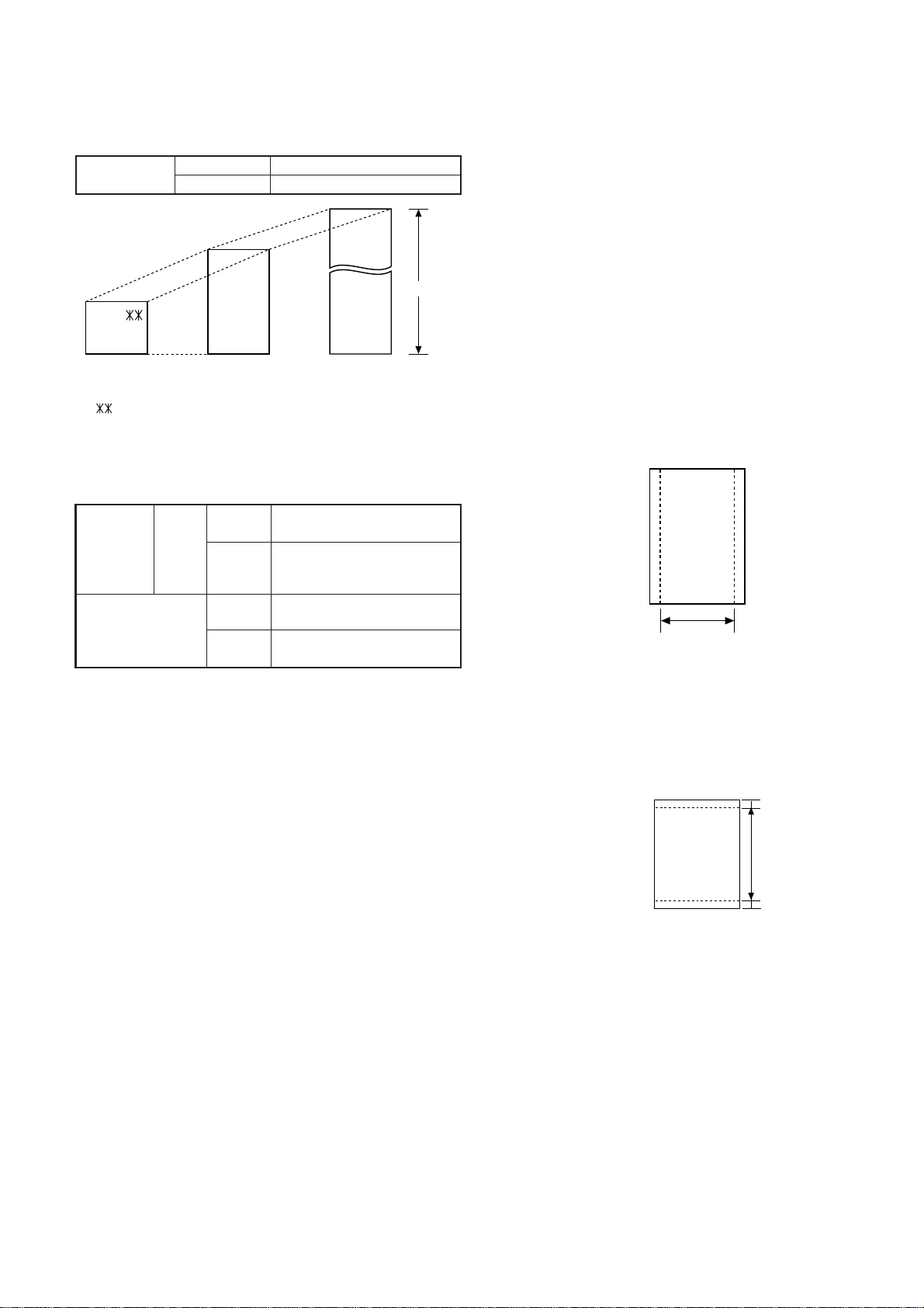
7. Use of Document Carrier Sheet
A document carrier sheet must be used for the following documents.
•Those with tears.
•Those smaller than size 148mm (W) x 128mm (L) .
•Carbon-backed documents
NOTE: To transmit a carbon-backed document, insert a white sheet of
paper between the carbon back of the document and the docu-
ment carrier.
•Those containing an easily separable writing substance (e.g., trac-
ing paper written on with a soft, heavy lead pencil).
NOTES: •When using the document carrier, carefully read the in-
structions written on the back.
•If the document carrier is dirty, clean it with a soft, moist
cloth, and then dry it before using for transmission.
•Do not place more than one document in the carrier at a
time.
[4] Installation
1. Site selection
Take the following points intoconsideration whenselecting a site for this
model.
ENVIRONMENT
•The machine must be installed on a level surface.
•Keep the machine away from air conditioners, heaters, direct sun-
light, and dust.
•Provide easy access to the front, back, and sides of the machine. In
particular, keep the area in front of the machine clear, or the original
document may jam as it comes out after scanning.
•The temperature should be between 5°and 35°C.
•The humidity should be between 30% and 85% (without conden-
sation).
ELECTRICITY
AC 230-240V, 50Hz, earthed (3-prong) AC outlet is required.
Caution!
•Connection to a power source other than that specified will cause
damage to the equipment and is not covered under the warranty.
•Ifyourarea experiences ahighincidenceof lightning orpowersurges,
we recommend that you install a surge protector for the power and
telephonelines.Surgeprotectors can be purchasedatmosttelephone
specialty stores.
If the machine is moved from a cold to a warm place...
If the machine is moved from a cold to a warm place, it is possible that
thereading glassmay fog up, preventing properscanning ofdocuments
for transmission. To remove the fog, turn on the power and wait approxi-
mately 2 hours before using the machine.
TELEPHONE JACK
A standard telephone jack must be located near the machine.
This is the telephone jack commonly used in most homes and offices.
•Plugging the fax machine into a jack which is not an jack may result
in damage to the machine or your telephone system. If you do not
know what kind of jack you have, or needed to have one installed,
contact the telephone company.
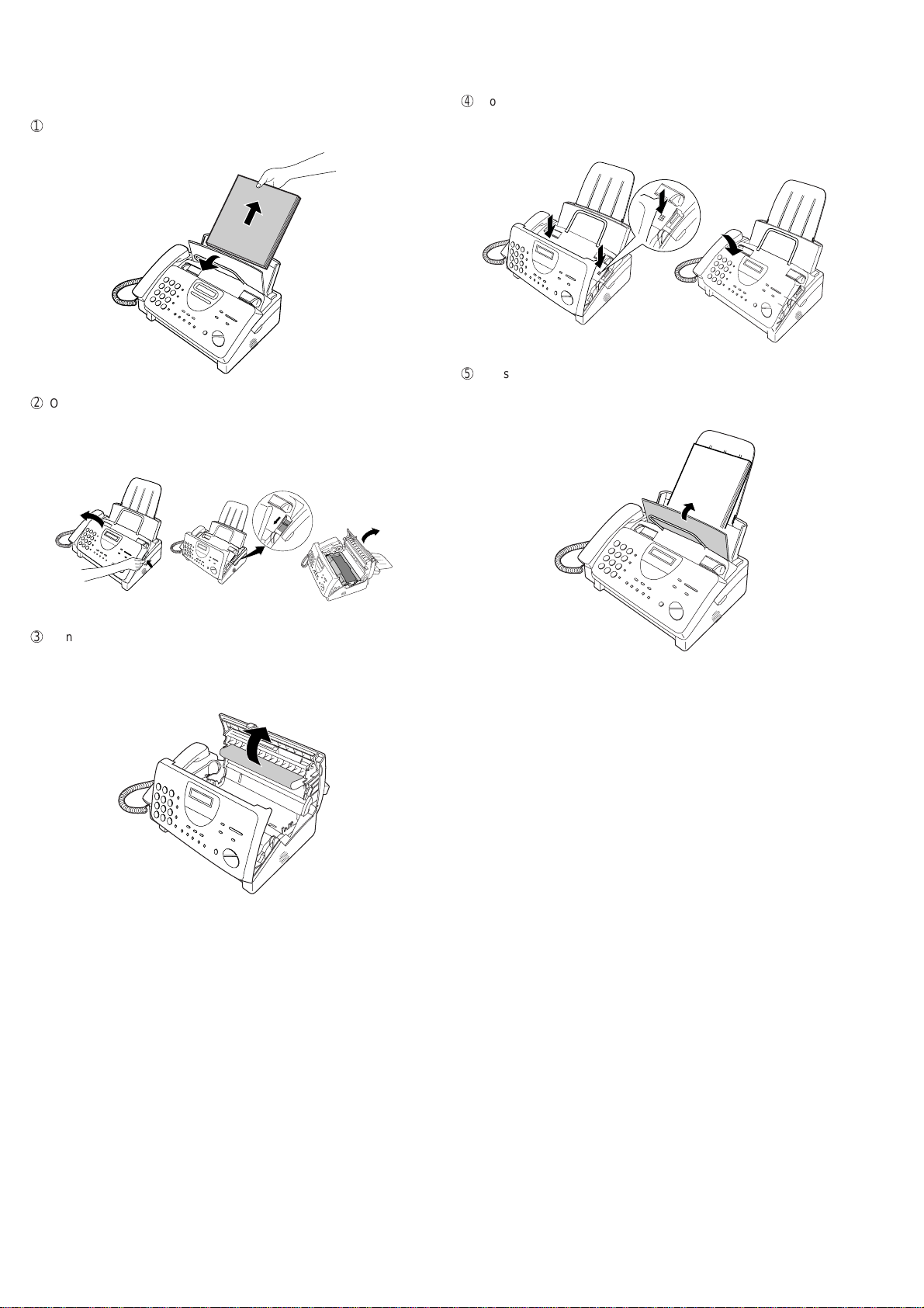
2. Loading the imaging film (FO-3CR)
Your fax uses a roll of imaging film to create printed text and images.
The print head in the fax applies heat to the imaging film to transfer ink
to the paper. Follow the steps below to load or replace the film.
•The initial starter roll of imaging film included with your fax can print
about 30A4 pages.
•When replacing the film, use a roll of Sharp FO-3CR imaging film.
One roll can print about 95A4 pages.
Note: If there is paper in the paper tray, pull the paper release plate
forward and remove the paper before loading the imaging film.
1
Open the operation panel by grasping the finger hold and pulling up.
Direction of insertion
Make print straight
across paper
E.G.
Place the document
carrier in the document
feeder with the clear film
side down
If you are installing the imaging film for the first
time, go to Step 6.
2
Pull the green release on the right side of the machine forward, and
open the print compartment cover.
3
Removethe imagingfilmcartridge fromtheprint compartment(grasp
the handle at the front of the cartridge) and turn it over.

1 – 5
FO-780A
4
Remove the used film from the cartridge.
5
Remove the four green gears from the used film.
DO NOT DISCARD THE FOUR GREEN GEARS!
6
Remove the new roll of imaging film from its packaging.
• Do not yet remove the band that holds the rolls together.
7
Insert the large gear into the green end of the empty spool. Make
sure the two protrusions on the large gear fit firmly into the slots in
the end of the spool.
Insert the remaining three gears into the spools, making sure the
protrusion on each gear fits firmly into one of the slots in the end of
each spool.
• If needed, pull the spools apart slightly to allow the gears to fit
(the band will stretch).
9
Cutthe band thatholdsthe twospoolstogether.Unrollthefilm slightly
and insert the small gears into their holders.
F
Turn the cartridge over, grasp the handle, and insert the cartridge
into the print compartment.
Slot
Protrusion
Large gear
8
Insertthe large gearintothe largeholderon the imagingfilmcartridge
(make sure it clicks into place), and then insert the small gear on the
other end of the spool into its holder.
G
Rotate the large gear toward you until the film is taut.
H
Closethe print compartmentcover(pressdown on bothsidesto make
sure it clicks into place), and then close the operation panel.
I
Load paper in the paper tray and then press the following keys to
initialize the film.
Note: Paper must be loaded before the film can be initialized. To
load paper, see the following section,
Loading the Printing Paper.
FUNCTION
6
START/MEMORY
INITIALIZE FILM
Display shows:
When to replace the imaging film.
Replace the imaging film when the display shows:
Use the following imaging film, which is available from your dealer
or retailer: Sharp FO-3CR Imaging Film
FILM END
Clik!

1 – 6
FO-780A
3. Assembly and connections
1
Plug the power Lead into a 230-240 V, 50 Hz, earthed (3-prong)AC
outlet.
•Caution: When disconnecting the fax, unplug the telephone line
cord before unplugging the power lead.
•Caution:Themainsoutlet (socketoutlet)should beinstallednear
the equipment and be easily accessable.
• The machine does not have a power on/off switch, so the power
isturned onand off by simplyplugging inor unplugging thepower
lead.
2
Connect the handset as shown and place it on the handset rest.
♦ The ends of the handset cord are identical, so they will go into
either jack.
3
Insert one end of the telephone line cord into the adapter. Insert the
otherend of thelinecordinto the socketonthe back ofthefaxmarked
TEL.LINE. Plug the adapter into the telephone socket on the wall.
Be sure to insert the telephone line cord into the TEL.LINE socket.
Do not Insert into the TEL.SET socket.
5
Attach the original document support.
Note: The original document support has a top side and a bottom
side.If youcannot insert thetabs on thesupport intotheholes,
turn the support over.
Make sure the handset cord
goes into the socket marked
withahandsetsymbol on the
side of the machine!
Use the handset to make ordinary
phonecalls,or to transmitandreceive
documents manually.
4
Attach the paper tray extension.
• Pullthe paper releaseplateforward. Insert thepapertray extension
horizontally into the notches in the paper tray. Rotate the paper
tray extension up until it snaps into place.
4. Loading printing paper
You can load A4 size paper in the paper tray. The maximum number of
sheets is:
♦60 for paper from 60 to 75 g/m2
♦50 for paper from 75 to 90 g/m2
1
Fan the paper, and then tap the edge against a flat surface to even
the stack.
TEL.
SET
TEL.
LINE
For Australia
For New Zealand
2
Pull the paper release plate toward you.

1 – 7
FO-780A
3
Insert the stack of paper into the tray, print side down.
• If paper remains in the tray, take it out and combine it into a single
stack with the new paper before adding the new paper.
• Be sure to load the paper so that printing takes place on the print
side of the paper. Printing on the reverse side may result in poor
print quality.
4
Push the paper release plate back down.
• If the paper release plate is not pushed down, paper feed errors will
result.
Note: When receiving faxes or copying documents, do not allow a
large number of pages to accumulate in the output tray. This may
obstruct the outlet and cause paper jams.
5
Your fax has been set at the factory to print at normal contrast.
Depending on the type of paper you have loaded, you may find that
you obtain better print quality by changing the setting to LIGHT.
Press these keys:
5. Clearing a jammed document
If the original document doesn’t feed properly during transmission or
copying, or DOCUMENT JAMMED appears in the display, first try
pressing the START/MEMORY key. If it doesn’t feed out, remove it as
follows:
Important:
Do not tryto remove adocument without openingthe operation panel.
This may damage the feeder mechanism.
1
Open the operation panel by grasping the finger hold and pulling up.
2
Remove the document.
3
Close the operation panel, making sure it clicks into place.
FUNCTION
6
The display will show: PRINT CONTRAST
Press 1to select NORMAL or 2to select LIGHT.
The display will show: COPY CUT-OFF
Press the STOP key to return to the date and time display.
1
or
2
NORMAL LIGHT
STOP
Click!

1 – 8
FO-780A
6. Clearing jammed printing paper
1
Pull the paper release plate forward and remove the paper.
2
Open the operation panel (grasp the finger hold and pull up), and
then pull the release on the right side of the machine forward to open
the print compartment cover.
4
Closethe print compartmentcover(pressdown on bothsidesto make
sure it clicks into place), and then close the operation panel.
3
Gently pull the jammed paper out of the machine, making sure no
torn pieces of paper remain in the print compartment or rollers.
5
Reinsert the paper in the paper tray and push the paper release plate
back down.
Clik!

1 – 9
FO-780A
[5] Quick reference guide
INSTALLATION
1. Connect the handset as shown.
2. Plug the power cord into a grounded, 230-240 V outlet.
3. Plug one end of the telephone line into the TEL. LINE socket on the rear of the
fax and the other end into the adapter. Plug the adapter into a telephone wall
socket.
CONNECTING ANANSWERING MACHINEAND/OR EXTENSION TELEPHONE
SETTING THE DATE AND TIME
Note: Imaging film and paper must be loaded to perform the following operation.
Press:
Display shows: DATE & TIME SET
Press the START/MEMORY key:
Enter two digits for the Day (01 through 31).
Enter two digits for the Month (01 through 12).
Enter four digits for the Year (Ex: 1999).
Enter two digits for the Hour (01 through 23).
Enter two digits for the Minute (00 through 59).
When finished, press:
STORING AND CLEARING NUMBERS FOR AUTOMATIC DIALING
Note: Imaging film and paper must be loaded to perform the following operation.
1. Press:
Display shows: FAX/TEL # MODE
2. Press 1to store a number or 2to clear a number.
3. Enter a 2-digit Speed Dial number (from 01 to 08 for Rapid Key Dialing, or 09
to 88 for Speed Dialing). (If you are clearing a number, go to Step 7.)
4. Enter the full telephone/fax number.
5. Press:
6. Enter the name of the location by pressing number keys (max. of 20 charac-
ters). (Refer to the letter entry table in ENTERING YOUR NAME AND
NUMBER.)
7. Press:
SENDING DOCUMENTS
Placeyourdocument(up to 10pages)
face down in the document feeder.
Normal Dialing
1. Lift the handset or press
2. Dial the fax number.
3. Wait for the reception tone (if a person answers, ask them to press their Start
key).
4. Press:
Rapid Key Dialing
Press the appropriate Rapid Key. Transmission will begin automatically.
Speed Dialing
1. Press:
2. Enter 2-digit Speed Dial number.
3. Press:
RECEIVING DOCUMENTS
Press:
FAX mode: Thefaxautomaticallyanswersonfourrings and receives the incoming
document.
TEL mode:
TEL/FAX mode:Thefaxmachineautomatically answers on two rings and receives
faxes. Voice calls (including manually dialed fax transmissions) are signalled by a
special ringing sound.
A.M. mode: Select this mode when an answering machine is connected to the fax
and the answering machine is turned on.
1. Remove the seal covering the TEL. SET socket on the rear of the fax. Connect
an extension telephone or answering machine to the TEL. SET socket.
2. If desired, connect an extension phone to the answering machine.
ENTERING YOUR NAME AND NUMBER
Note: Imaging film and paper must be loaded to perform the following operation.
1. Press:
FUNCTION
3
Display shows: OWN NUMBER SET
2. Press:
3. Enter your fax number (max. of 20 digits) by pressing the number keys.
♦If you make a mistake, press the HOLD/SEARCH key to move the cursor
back to the mistake, then enter the correct number or letter.
4. Press:
5. Enter your name by pressing the appropriate number keys as shown below.
♦To entertwo lettersin succession thatrequire thesame key,press the SPEAKER
key after entering the first letter.
6. When finished, press:
START/MEMORY
A =
B =
C =
D =
E =
F =
G =
H =
I =
J =
K =
L =
M =
N =
O =
P =
Q =
R =
S =
T =
U =
V =
W =
X =
Y =
Z =
SPACE =
START/MEMORY
STOP
FUNCTION
3
SPEAKER
SPEED DIAL
START/MEMORY
START/MEMORY
START/MEMORY
STOP
START/MEMORY
START/MEMORY
STOP
START/MEMORY
START/MEMORY
TEL.
SET TEL.
LINE
1
2
3
TEL.
SET TEL.
LINE
FUNCTION
3
FAX
TEL
A.M.
14 FEB 10:30
TEL/FAX
FAX
TEL
A.M.
14 FEB 10:30
TEL/FAX
FAX
TEL
A.M.
14 FEB 10:30
TEL/FAX
FAX
TEL
14 FEB 10:30
A.M.TEL/FAX
RECEPTION
MODE
Fax
tone
RECEIVING
START/MEMORY
SPEED
DIAL
REDIAL
HOLD/
SEARCH
SPEAKER
ABC DEF
JKL MNO
GHI
TUV WXYZ
PQRS
Deletes high-
lighted letter
Upper/lower
case shift key
Moves cursor
to the left
Moves cursor
to the right
Press either key one or more times to select
and enter a symbol.

1 – 10
FO-780A
[6] Option imaging film specifications
(FO-3CR)
1. Structure
Thisarticle is composedofpolyester film coatedwith heat-resistantlayer,
matt layer and hot melt ink layer, leader film and paper core. Ink film
specification is "DNP standard ink film HC".
Heading Requirements Measuring method
Material Polyethylene-
terephthalate –
Heading Requirements Measuring method
Grade HR Mixer P-5 –
Heading Requirements Measuring method
Grade ML Sumi –
Heading Requirements Measuring method
Grade #507W –
2. Details of compositions
2-1. Base film
2-2. Heat resistant layer
2-3. Matt layer
2-4. Hot melt ink layer
,,,,
,,,,
1
2
3
4
1
2
3
4
Heat Resistant Layer
Base Film
Matt Layer
Hot melt Ink Layer

FO-780A
CHAPTER 2. ADJUSTMENTS
[1] Adjustments
General
Sincethe following adjustmentsand settings areprovided for thismodel,
make adjustments and/or setup as necessary.
1. Adjustments
Adjustments of output voltage (FACTORY ONLY)
1. Install the power supply unit in the machine.
2. Set the recording paper and document.
3. When the document is loaded, power is supplied to the output lines.
Confirm that outputs are within the limits below.
Output voltage settings
(1)FU100 (ICP-S07) is installed in order to protect IC’s from an over-
current generated in the motor drive circuit. If FU100 is open, replace
it with a new one.
3. Settings
(1) Dial mode selector
DIAL mode (Soft Switch No. SWB4 DATA No. 3)
Output Voltage limits
+5V 4.75V ∼ 5.25V
+24V 23.3V ∼ 24.7V
2. IC protectors replacement
ICPs (IC Protectors) are installed to protect the motor driver circuit.
ICPsprotect variousICsand electroniccircuitsfrom anovercurrent con-
dition.
The location of ICPs are shown below:
1MG
2MG
3 +24V
4 +24V
5 +24V
6DG
7 +5V
8DG
9 PSAVE
Connector
No. CNPW
Pin No.
2 – 1
TEL/LIU PWB
POWER
SUPPLY
PWB
CONTROL
PWB
CNLIUA
CNLIUA CN1
CNPW
CNTH
CNPN
CNCIS
CNSP
CNMT
CNCSW
CNLIUB
CNLIUB
CONTROL PWB
(BOTTOM SIDE)
CNPW CNLIUA
FU100
CNLIUB
(step 1) Select "OPTION SETTING".
KEY : FUNCTION 4
DISPLAY: OPTION SETTING PRESS OR #
(step 2) Select "DIAL MODE".
KEY: Push # until " DAIL MODE " is
indicated because the number of
# s changes by the model.
DISPLAY: DIAL MODE
(step 3) Select, using "1" or "2".
KEY: 1
DISPLAY: TONE SELECTED
KEY: 2
DISPLAY: PULSE SELECTED
(step 4) End, using the "STOP" key.
KEY:
Cursor
When initially registering,
the mode shows 1=TONE.
When registering again, the
mode which was registered
formerly is shown.
STOP
1=TONE, 2=PULSE

FO-780A
[2] Diagnostics and service soft switch
1. Operating procedure
(1) Entering the diagnostic mode
Press FUNC →9 →→ 8 →# →7 , and the following display will appear.
ROM Ver. FMU0 After 2 sec: DIAG MODE
FMU0
Then press the START key. Select the desired item with the key or the # key or select with the rapid key. Enter the mode with the START key.
(Diag•specifications)
If the diag mode cannot be set, repeat the diag mode operation, per-
forming the following operation.
After the power is turned on and "WAITAMOMENT" is indicated, press
the STOP key.
2 – 2
In relation with the process response (request from Production
Engineering)"WAITAMOMENT"clock indication mayappeardepending
onSTOPkey timing.If the STOPkey ishelddown, "MEMORY CLEAR?"
appears.
2. Diagnostic items
ITEM DIRECT
No. key
1 1 SOFT SWITCH MODE Soft switches are displayed and changed. List can be output.
2 2 ROM & RAM CHECK ROM is sum-checked, and RAM is matched. Result list is output.
3 3 AGING MODE 10 sheets of check patterns are output every 5 minutes per sheet.
4 4 PANEL KEY TEST Panel keys are tested. Result list is output.
5 5 CHECK PATTERN Check pattern is output.
6 6 SIGNAL SEND MODE Various signals of FAX communication are output.
7 7 MEMORY CLEAR Back-up memory is cleared, and is set at delivery.
8 8 SHADING MODE Shading compensation is performed in this mode.
9 — ALL BLACK PRINT To check the print head, whole dots are printed over the interval of 2 m.
10 — AUTO FEEDER MODE Insertion and discharge of document are tested.
11 — ENTRY DATA SEND Registered content is sent.
12 — ENTRY DATARECEIVE Registered content is received, and its list is output.
Contents Function
FUNC DIAG MODE
9 8 7
START 1Soft switch mode
START 2ROM & RAM check
START 3Aging mode
START 4Panel key test
START 5Check pattern
START 6Signal send mode
Shading mode
START
START
All black mode
START Auto feeder mode
START
Entry data send
Entry data receive
START
START8
START
KEY
STOP
KEY +
+
"Power ON"
Memory clear
(Work + Backup)
FMU0
Memory clear
START
7

FO-780A
3. Diagnostic items description
3. 1. Soft switch mode
Used to change the soft switch settings.
The soft switch which is stored internally is set by using the keys.
The available soft switches are SW-A1 to SW-M2.
The content of soft switches is shown in page 2-5 to 2-16.
The contents are set to factory default settings.
3. 2. ROM & RAM check
ROM executes the sum check, and RAM executes the matching test.
The result will be notified with the number of short sounds of the buzzer
as well as by printing the ROM & RAM check list.
Number of short sounds of buzzer 0 →No error
1 → ROM error
2 → RAM error (32Kbyte)
3. 3. Aging mode
Ifany documentisfirst present,copyingwill beexecuted sheet bysheet.
If no document is present, the check pattern will be printed sheet by
sheet. This operation will be executed at a rate of one sheet per 5min-
utes, and will be ended at a total of 10 sheets.
3. 4. Panel key test
This mode is used to check whether each key operates properly or not.
Press the key on the operation panel, and the key will be displayed on
thedisplay.Therefore, pressall keys.At thistime,finally press the STOP
key.
When the STOP key is pressed, the keys which are not judged as
"pressed" will be printed on the result list.
• LED port of the contact image sensor (CIS) is kept on during the term
from when start of the panel test mode to end with the STOP key.
3. 5. Check pattern
This mode is used to check the state of the printing head. It is ended
with the following pattern printed on one printing sheet.
1
Longitudinal stripe 2 Approx. 30 mm
2 black dots and 2 white dots are repeatedly progressed on one
line.
2
Full black Approx. 30 mm
3. 6. Signal send mode
This mode is used to send various signals to the circuit during FAX com-
munication. Every push of START key sends a signal in the following
sequence.Moreover, thesignal soundisalso outputto thespeakerwhen
the line monitor of the soft switch is on.
[1] No signal (CML signal turned on)
[2] 9600bps
[3] 7200bps
[4] 4800bps
[5] 2400bps
[6] 300bps (FLAG)
[7] 2100Hz (CED)
[8] 1100Hz (CNG)
[9] END
3. 7. Memory clear
This mode is used to clear the backup memory and reset to the default
settings.
3. 8. Shading mode
The mode is used for the shooting compensation. For reading, set up
the special original paper.
The shooting compensation memorizes the reference data of white and
black for reading.
Moreover, the memorized data is not erased even if memory clear mode
is executed.
3. 9. All black print
This mode is used to check the state of the printing head and inten-
tionally overheat it. Whole dots are printed over the interval of 2 m. If it is
overheatedor theprinting sheet isjammed, press STOPkey fortheend.
3. 10. Auto feeder mode
In this mode, a document is inserted and discharged to check the auto
feed function.
After this mode is started, set a document, and the document feed will
be automatically tested.
3. 11. Entry data send
This mode is used to send the registered data to the other machine and
make the other machine copy the registered content.
Before sending in this mode, it is necessary to set the other machine at
the entry data receive mode.
The following, information will be sent to the remote machine:
1. Telephone list data
2. Sender register data
3. Optional setting content
4. Soft switch content
5. Junk fax number list
6. Timer reservation data (only on the model which timer reserva-
tion is possible)
7. Recording setting list data
2 – 3
1
2

FO-780A
3. 12. Entry data receive
In this mode, the registered data sent from the other machine is receiv-
ed and the received data is registered in the machine. When this mode
is used for receiving, the other machine must be in the entry data send
mode.
After receiving is completed, the following lists are printed.
1. Telephone list data
2. Senderregisterdata (The passcodeNo.isalso printed ifthepoling
function is provided.)
3. Optional setting list
4. Soft switch content
5. Junk fax number list
6. Timer reservation list (only model which timer communication is
possible)
7. Recording setting list data
4. How to make soft switch setting
To enter the soft switch mode, make the following key entries in se-
quence.
2 – 4
Press FUNCTION 9 8 7 STARTSTART
Press FUNCTION key.
Press key.
Press key.
Bit1 - 8 are set.
Soft SW-A2 - SW-M2 are set.
S F T SW-A1 = 1 0 0 0 0 0 0 0
S F T SW-A2 = 0 0 0 0 0 0 0 0
S F T SW-M2 = 0 0 0 0 0 0 0 0
Press key during setting.
To finish the settings halfway between
SW-A1 and SW-M2, press the STOP
key. In this case, the setting being done
to the SW No. on display will be nullified
while settings done to the preceding
SW Nos. remain in effect.
The soft switch mode is terminated.
S F T SW-A1 = 0 0 0 0 0 0 0 0
START
DATA No. 1 2 3 4 5 6 7 8
When the COPY key is pressed, the
contents of soft switches are printed.

FO-780A
1 Protect from echo No Yes 0
2 Forced 4800 BPS reception Yes No 0
3 Footer print Yes No 0
4 Length limitation of copy/send/receive No limit Copy/send: 1m 0
Receive: 1.5m
5 CSI transmission No transmitted Transmitted 0
6 DIS receive acknowledgement during G3 Twice NSF: Once 0
transmission DIS: Twice
7 Non-modulated carrier for V29 transmission Yes No 0
modem
8 EOL detect timer 25 s 13 s 0
Modem speed V.29 V.27 ter
9600bps 7200bps 4800bps 2400bps
1 No. 1 0 0 0 0 0
2 No. 2 0 0 0 0 0
3 No. 3 0 1 1 0 0
4 No.4 1 1 0 0 1
5 Sender’s information transmit No Yes 0
6 H2 mode No Yes 0
7 Communication error treatment in RTN No communication error Communication error 0
sending mode (reception)
8 CNG transmission No Yes 0
CED tone signal interval 1000ms 750ms 500ms 75ms
1 No. 1 1 1 0 0 0
2 No. 2 1 0 1 0 0
3 MR coding No Yes 0
4 Reserved 0
5 Reserved 0
6 Reserved 0
7 Reserved 0
8 Reserved 0
1 Signal transmission level Binary input 0
2 No. = 16 8 4 2 1 1
3 1 2 3 4 5 1
4 0 1 1 1 1 1
5 1
6 Protocol monitor (error print) Printed at com. err Not printed 0
7 Protocol monitor Yes No 0
8 Line monitor Yes No 0
Digital line equalization setting (Reception) 7.2km 0km
1 No. 1 1 0 1
2 No. 2 1 0 1
3 Reserved 0
4 Reserved 0
Digital cable equalizer setting (Reception 7.2km 0km
5 for Caller ID) No. 5 1 0 0
6 No. 6 1 0 0
7 Error criterion 10 ~ 20 % 5 ~ 10 % 0
8 Anti junk fax check Yes No 0 OPTION
5. Soft switch description
• Soft switch
SW
NO. DATA
NO. ITEM Switch setting and function
10
Remarks
Initial
setting
SW
l
A1
SW
l
A2
SW
l
A3
SW
l
A5
SW
l
A4
2 – 5

FO-780A
1 Auto gain control (MODEM) Enable Disable 1
2 End Buzzer Yes No 1
3 Disconnect the line when DIS is received in No Yes 1
RX mode
4 Equalizer freeze control (MODEM) On Off 0
5 Equalizer freeze control 7200 BPS only No Yes 0
6 CNG transmission in manual TX mode Yes No 1
7 Initial compression scheme for sharp fax in MR mode H2 mode 0
TX mode
8 Reserved 0
1 Recall interval Binary input 0
2 No. = 8 4 2 1 1
3 1 2 3 4 0
4 0 1 0 1 1
5 Recall times Binary input 0
6 No. = 8 4 2 1 0
7 5 6 7 8 1
8 0 0 1 0 0
1 Dial pausing (sec/pause) 4 sec 2 sec 0
2 Reserved 0
3 Reserved 0
4 Reserved 0
5 Waiting time after dialing 90 sec 45 sec 0
6 Reserved 0
7 Reserved 0
8 Reserved 0
1 Reserved 0
2 Reserved 0
3 Reserved 0
4 Reserved 0
5 Reserved 0
6 Reserved 0
7 Reserved 0
8 Reserved 0
1 Auto Dial Mode Delay timer of before line 3 sec 0 sec 1
connect
2 Auto Dial Mode Delay timer of after line 3.6 sec 3 sec 0
connect
3 Dial mode Tone Pulse 1 OPTION
4 Pulse →Tone change function by key Enable Disable 1
5 Dial pulse make/break ratio(%) 40/60 33/67 0
6 Reserved 0
7 Reserved 0
8 Reserved 0
1 DTMF signal transmission level (Low) Binary input 1
2 No. = 16 8 4 2 1 0
3 1 2 3 4 5 1
4 1 0 1 0 1 0
5 1
6 Reserved 0
7 Reserved 0
8 Reserved 0
SW
NO. DATA
NO. ITEM Switch setting and function
10Remarks
Initial
setting
SW
l
B5
SW
l
B4
SW
l
B3
SW
l
B2
SW
l
B1
SW
l
A6
2 – 6

FO-780A
1 DTMF signal transmission level (High) Binary input 1
2 No. = 16 8 4 2 1 0
3 1 2 3 4 5 0
4 1 0 0 1 0 1
5 0
6 Reserved 0
7 Reserved 0
8 Reserved 0
Reading slice (Binary) Factory Light Dark Darker in
setting dark mode
1 No. 1 0 1 0 1 0
2 No. 2 0 0 1 1 0
Reading slice (Half tone) Factory Light Dark Darker in
setting dark mode
3 No. 3 0 1 0 1 0
4 No. 4 0 0 1 1 0
5 Line density selection Fine Standard 0 OPTION
6 Reserved 0
7 MTF correction in half tone mode No Yes 0
8 Reserved 0
1 Number of rings for auto receive Binary input 0 OPTION
2 No. = 8 4 2 1 0
3 1 2 3 4 1
4 0 0 1 0 0
5 Automatic switching manual to auto receive Reception after 4 rings No reception 0 OPTION
mode
6 Reserved 0
7 Reserved 0
8 Reserved 0
1 Reserved 0
2 Reserved 0
3 Reserved 0
4 Distinctive ringing detection Yes No 0 OPTION
5 Caller ID function Yes No 0 OPTION
CI off detection timer (Distinctive ring 1200ms 1000ms 700ms 350ms
6 setting off only) No. 6 0 1 0 1 0
7 No. 7 0 0 1 1 1
8 Caller ID detect during CI off All times Only first 1
1 Tel/Fax Automatic switching mode Tel/Fax auto switch Switch to Fax 1
Pseudo ringing time at phone/fax 15sec 60sec 30sec 120sec OPTION
2 automatic switching mode No. 2 0 0 1 1 0
3 No. 3 0 1 0 1 0
4 Number of CNG signal detection at the Twice Once 1
tel/fax automatic switching mode
5 CNG detection when TEL/FAX mode 3sec 5sec 0
6 Reserved 0
7 Post answer tone (transmit in Tel/Fax mode) No Yes 0
8 Country select for Caller ID New Zealand Australia 0 OPTION
2 – 7
SW
NO. DATA
NO. ITEM Switch setting and function
10Remarks
Initial
setting
SW
l
B6
SW
l
C1
SW
l
D2
SW
l
D1
SW
l
E1

FO-780A
1 Pseudo ringer sound volume Binary input 0
2 No. = 8 4 2 1 1
3 1 2 3 4 0
4 0 1 0 1 1
5 Reserved 0
6 Reserved 0
7 Reserved 0
8 Reserved 0
DTMF detection time 50ms 80ms 100ms 120ms
1 No. 1 0 0 1 1 0
2 No. 2 0 1 0 1 0
3 Protection of remote reception (5 ) detect Yes No 0 OPTION
4 Remote reception with GE telephone Compatible Not compatible 1
5 Remote operation code figure by external Binary input 0 OPTION
6 TEL (0~9) No. = 8 4 2 1 1
7 5 6 7 8 0
8 0 1 0 1 1
1 CNG detection in STAND-BY mode Yes No 1 OPTION
Number of CNG detect (AM mode) 1pulse 2pulses 3pulses 4pulses
2 No. 2 0 0 1 1 0
3 No. 3 0 1 0 1 1
Number of CNG (STAND-BY mode) 1pulse 2pulses 3pulses 4pulses
4 No. 4 0 0 1 1 0
5 No. 5 0 1 0 1 1
6 Reserved 0
7 Reserved 0
8 Reserved 0
1 Quiet detect time Binary input 0 OPTION
2 No. = 8 4 2 1 1
3 1 2 3 4 0
4 0 1 0 0 0
5 Quiet detect start timing Binary input 0
6 No. = 8 4 2 1 1
7 5 6 7 8 0
8 0 1 0 1 1
1 Reserved 0
2 Reserved 0
3 Reserved 0
4 Reserved 0
5 Reserved 0
6 Reserved 0
7 Reserved 0
8 Reserved 0
OGM detect timer Not 100ms 200ms 300ms
Work
1 No. 1 0 0 1 1 0
2 No. 2 0 1 0 1 1
3 Reserved 0
4 Reserved 0
Section time of quiet detection 30s 40s 50s 60s
5 No. 5 0 0 1 1 0
6 No. 6 0 1 0 1 1
7 Reserved 0
8 Reserved 0
SW
l
F1
SW
l
E2
SW
l
F2
SW
l
G1
SW
l
G2
SW
l
G3
SW
NO. DATA
NO. ITEM Switch setting and function
10Remarks
Initial
setting
2 – 8
Table of contents
Other Sharp Fax Machine manuals

Sharp
Sharp FO-4650 User manual

Sharp
Sharp UX-510 User manual

Sharp
Sharp FO-A760 User manual

Sharp
Sharp AL-2060 User manual

Sharp
Sharp FO-2950M - B/W Laser - All-in-One User manual

Sharp
Sharp FO-781 User manual

Sharp
Sharp UX-310 User manual

Sharp
Sharp UX-P200 User manual

Sharp
Sharp FO IS125N - B/W Laser - All-in-One User manual

Sharp
Sharp UX-465L User manual