Sharp UX-A1000 User manual

UX-A1000U
No. 00ZUA1000USME
Parts marked with " " are important for maintaining the safety of the set. Be sure to replace these parts with specified ones for
maintaining the safety and performance of the set.
This document has been published to be used
for after sales service only.
The contents are subject to change without notice.
SHARP CORPORATION
SERVICE MANUAL
FACSIMILE
UX-A1000
MODEL SELECTION CODE DESTINATION
UX-A1000 U
U.S.A.
MODEL
CHAPTER 1. GENERAL DESCRIPTION
[1] Specifications ............................................ 1-1
[2] Operation panel......................................... 1-2
[3] Transmittable documents .......................... 1-3
[4] Installation ................................................. 1-4
[5] Quick setup guide ..................................... 1-9
[6] Quick reference guide ..............................1-10
CHAPTER 2. ADJUSTMENTS
[1] Adjustments............................................... 2-1
[2] Diagnostics and service soft switch .......... 2-3
[3] Troubleshooting....................................... 2-25
[4] Error code table....................................... 2-26
CHAPTER 3. MECHANISM BLOCKS
[1] General description .................................. 3-1
[2] Ink jet printer ............................................ 3-3
[3] Disassembly and assembly
procedures ....................................... 3-6
CHAPTER 4. DIAGRAMS
[1] Block diagram ............................................4-1
[2] Wiring diagram .......................................... 4-2
[3] Point-to-point diagram............................... 4-3
CHAPTER 5. CIRCUIT DESCRIPTION
[1] Circuit description...................................... 5-1
[2] Circuit description of control PWB..............5-2
[3] Circuit description of TEL/LIU PWB ........ 5-13
[4] Circuit description of printer PWB ............5-15
[5] Circuit description of
power supply PWB............................5-18
[6] Circuit description of CIS unit...................5-18
CHAPTER 6. CIRCUIT SCHEMATICS AND
PARTS LAYOUT
[1] Control PWB circuit ................................... 6-1
[2] TEL/LIU PWB circuit ............................... 6-10
[3] Printer PWB circuit ...................................6-14
[4] Power supply PWB circuit ...................... 6-20
[5] Operation panel PWB circuit ................... 6-22
[6] Ink PWB circuit........................................ 6-24
CHAPTER 7. OPERATION FLOWCHART
[1] Protocol ..................................................... 7-1
[2] Power on sequence .................................. 7-2
CHAPTER 8. OTHERS
[1] Service tools.............................................. 8-1
[2] Changing the record paper size ................ 8-6
[3] Rewriting version up the FLASH ROM
Refer to the Service Manual of UX-B700U
PARTS GUIDE
CONTENTS

UX-A1000U
(Danish) ADVARSEL!
Lithiumbatteri-Eksplosionsfare ved fejlagtig håndtering.
Udskiftning må kun ske med batteri af samme fabrikat og type.
Levér det brugte batteri tilbage til leverandoren.
(English) Caution !
Danger of explosion if battery is incorrectly replaced.
Replace only with the same or equivalent type
recommended by the equipment manufacturer.
Discard used batteries according to manufacturer’s
instructions.
(Finnish) VAROITUS
Paristo voi räjähtää, jos se on virheellisesti asennettu.
Vaihda paristo ainoastaan laitevalmistajan suosittelemaan
tyyppiin. Hävitä käytetty paristo valmistajan ohjeiden
mukaisesti.
(French) ATTENTION
Il y a danger d’explosion s’ il y a remplacement incorrect
de la batterie. Remplacer uniquement avec une batterie du
même type ou d’un type recommandé par le constructeur.
Mettre au rébut les batteries usagées conformément aux
instructions du fabricant.
(Swedish) VARNING
Explosionsfare vid felaktigt batteribyte.
Använd samma batterityp eller en ekvivalent
typ som rekommenderas av apparattillverkaren.
Kassera använt batteri enligt fabrikantens
instruktion.
(German) Achtung
Explosionsgefahr bei Verwendung inkorrekter Batterien.
Als Ersatzbatterien dürfen nur Batterien vom gleichen Typ oder
vom Hersteller empfohlene Batterien verwendet werden.
Entsorgung der gebrauchten Batterien nur nach den vom
Hersteller angegebenen Anweisungen.
CAUTION FOR BATTERY REPLACEMENT

1 – 1
UX-A1000U
As a part of our policy of continuous improvement, SHARP reserves the right to make design and specification changes for product
improvement without prior notice. The performance specification figures indicated are nominal values of production units. There may be some
deviation from these values in individual units.
[1] Specifications
Automatic dialing Rapid Key Dialing: 18 numbers
Speed Dialing: 81 numbers
Print cartridge yield* Initial cartridge
(at 4% coverage**)
Ink save mode ON:Approx. 300 letter pages
Ink save mode OFF:Approx. 200 letter pages
Replacement cartridge: SHARP UX-C70B
Ink save mode ON:Approx. 600 letter pages
Ink save mode OFF:Approx. 400 letter pages
Memory size**
1.8 MB (approx. 100 average pages;20 minutes
of voice messages (including OGMS))
Modem speed
14,400 bps with auto fallback to lower speeds.
Transmission time** Approx. 6 seconds (only when ECM is on)
Scanning Resolution Horizontal:
203 lines/inch (8 lines/mm)
Vertical:
Standard: 98 lines/inch
(3.85 lines/mm)
Fine /Halftone: 196 lines/inch
(7.7 lines/mm)
Super fine: 391 lines/inch
(15.4 lines/mm)
Print resolution 600 x 600 dpi
Automatic document Letter/A4: 20 pages max. (20-lb. paper)
feeder Legal: 5 pages max.
Recording system Thermal inkjet
Halftone (grayscale) 64 levels
Paper tray capacity Letter:Approx. 200 sheets (20-lb. copier
paper at room temperature; maximum stack
height should not be higher than the line on
the tray)
Legal: 100 sheets
Recommended paper weight:
20-lb. Copy Bond
Compression scheme MR, MH, MMR
Compatibility ITU-T (CCITT) G3 mode
Input document size Automatic feeding:
Width: 5.8 to 8.5" (148 to 216 mm)
Length (20 pages): 5.5 to 11" (140 to 279 mm)
Length (5 pages): 5.5 to 14" (140 to 356 mm)
Manual feeding:
Width: 5.8 to 8.5" (148 to 216 mm)
Length: 5.5 to 23.6" (140 to 600 mm)
Effective scanning width
8.3" (210 mm) max.
Effective printing width
8.0" (203 mm) max.
Contrast control Automatic/Dark selectable
Reception modes TEL/FAX/TAD
Copy function Single/Multi/Sort (99 copies/page)
Telephone function Yes (cannot be used if power fails)
Applicable telephone Public switched telephone network
line
Display 16-digit LCD display
Power requirements 120 V AC, 60 Hz
Operating temperature
60 - 90°F (15 - 32°C)
Humidity 25 - 80% RH
Power consumption Standby: 5.0 W
Maximum: 30 W
Dimensions (without Width: 14.6" (372 mm)
attachments) Depth: 10.2" (259 mm)
Height: 8.0" (203 mm)
Weight (without Approx. 11 lbs. (5.0 kg)
attachments)
* Ink Save mode is initially turned off.
** Based on Sharp Standard No. 1 Chart at standard resolution,
excluding time for protocol signals (i.e., ITU-T phase C time only).
CHAPTER 1. GENERAL DESCRIPTION

1 – 2
UX-A1000U
[2] Operation panel
DEF
TAD
1 2 3
4 5 6
7 8 9
0
TEL FAX
MNO
WXYZ
ABC
JKL
TUV
GHI
01 02 03 04 05 06
07 08 09 10 11 12
13 14 15 16/POLL 17/G1 18/G2
PQRS
RESOLUTION
/
REC/MEMO
PLAY
HOLD
SPEED DIAL
FUNCTION
COPY/HELP
STOP
REDIAL
Z
UP
PLAIN PAPER INKJET FAX
DOWN
START/
MEMORY
SPEAKER
RECEPTION MODE
PANEL RELEASE
DELETEREPEAT SKIP
7
1 2 34 5 6
8910 1112 13 14 15 16 17 18
A
Display
This displays messages and prompts to help you operate the machine.
REC/MEMO key
Press this key to record an outgoing message, phone conversation, or
memo.
PLAY key
Press this key to play recorded messages.
FUNCTION key
Press this key followed by the arrow keys to select special functions
and settings.
RESOLUTION / RECEPTION MODE key
When a document is in the feeder, press this key to adjust the resolution
for faxing or copying. At any other time, press this key to select the
reception mode (an arrow in the display will point to the currently selected
reception mode).
Rapid Dial Keys
Press one of these keys to dial a fax number automatically
Number keys
Use these keys to dial numbers, and enter numbers and letters when
storing auto-dial numbers.
2
3
4
5
6
7
1
REPEAT key
Press this key while listening to a message to play it again.
SKIP key
Press this key while listening to a message to skip to the next message.
8
9
DELETE key
Press this key to erase recorded messages.
10
SPEED DIAL key
Press this key to dial a fax or voice number using an abbreviated 2-
digit Speed Dial number.
SPEAKER key
Press this key to listen to the line and fax tones through the speaker
when faxing a document.
Note: This is not a speakerphone. You must pick up the handset
to talk with the other party.
HOLD key
Press this key to put the other party on hold during a phone
conversation.
PANEL RELEASE
Grasp here and pull up to open the operation panel.
COPY/HELP key
When a document is in the feeder, press this key to make a copy of
a document. At any other time, press this key to print out the Help List,
a quick reference guide to the operation of your fax machine.
STOP key
Press this key to cancel an operation before it is completed.
START/MEMORY key
Press this key after dialing to begin fax transmission. Press this key
before dialing to send a fax through memory. The key can also be
pressed in the date and time display to show the percentage of
memory currently used.
Arrow keys
Use these keys to scroll through and select settings, and to search
for auto-dial numbers.
11
12
13
14
15
16
17
18

1 – 3
UX-A1000U
[3] Transmittable documents
1. Document Sizes
* With special sizes, only one sheet can be fed into the machine at a
time. Insert next page into feeder as current page is being scanned.
2. Paper Thickness & Weight
Normal size width 5.8" - 8.5" (148 – 216 mm)
length 5.5" - 11" (140 – 279 mm)
5. Automatic Document Feeder Capacity
Number of pages that can be placed into the feeder at anytime is as
follows:
Normal size: max. ADF 20 pages
Special size: Single sheet only (manual feeding)
NOTES: •Whenyouneedtosendorcopymorepagesthanthefeeder
limit, place additional pages in feeder when last page in
feeder is being scanned.
•Place additional pages carefully and gently in feeder.
If force is used, double-feeding or a document jam may
result.
6. Readable Width & Length
The readable width and length of a document are slightly smaller than
the actual document size.
Note that characters or graphics outside the effective document scan-
ning range will not be read.
•Readable width
8.3" (210mm), max.
•Readable length
This is the length of the document sent minus 0.16" (4mm) from the top
and bottom edges.
Use document carrier sheet for smaller documents.
Readable width
(Min.) (Max.)
Letter
size
(Max.)
140mm
279mm 600mm
148mm 216mm
[
Normal size
]
216mm
[
Special size
]
3. Document Types
• Normal paper
Documents handwritten in pencil (No. 2 lead or softer), fountain pen,
ball-point pen, or felt-tipped pen can be transmitted.
Documents of normal contrast duplicated by a copying machine can
also be transmitted.
• Diazo copy (blue print)
Diazo copy documents of a normal contrast may be transmitted.
• Carbon copy
A carbon copy may be transmitted if its contrast is normal.
4. Cautions on Transmitting Documents
• Documents written in yellow, greenish yellow, or light blue ink cannot
be transmitted.
• Ink, glue, and correcting fluid on documents must be dry before the
documents can be transmitted.
• All clips, staples and pins must be removed from documents before
transmission.
• Patched (taped) documents should be copied first on a copier and
then the copies used for transmission.
• All documents should be fanned before insertion into the feeder to
prevent possible double feeds.
4mm
4mm
Readable length
20 sheets 1sheet(Manual)
Paper weight 70 kg 70 kg ~ 135 kg
21.5 lbs. 14 lbs. ~ 42 lbs.
(80 g/m2) (52 g/m2
~ 157g/
m2)
Paper thickness (ref.)
0.1 mm 0.1 mm ~ 0.18mm
Paper size LGL (216 mm x 355.6 mm)
A4 (210 mm x 297 mm)
LTR (216 mm x 279 mm)
Feeder capacity A4/LTR: 20 sheets
LGL : 5 sheet

1 – 4
UX-A1000U
[4] Installation
1. Site selection
Takethefollowing points into considerationwhenselectinga site forthis
model.
ENVIRONMENT
•The machine must be installed on a level surface.
•Keep the machine away from air conditioners, heaters, direct sun-
light, and dust.
•Provide easy access to the front, back, and sides of the machine. In
particular, keep the area in front of the machine clear, or the original
document may jam as it comes out after scanning.
•The temperature should be between 41 - 95°F(5 - 35°C).
•The humidity should be between 25% and 85% (without conden-
sation).
ELECTRICITY
AC 120V, 60Hz, grounded(3-prong) AC outlet is required.
Caution!
•Connection to a power source other than that specified will cause
damage to the equipment and is not covered under the warranty.
•Ifyourareaexperiencesahighincidenceoflightningorpower surges,
we recommend that you install a surge protector for the power and
telephonelines.Surgeprotectorscanbepurchasedatmosttelephone
speciality stores.
If the machine is moved from a cold to a warm place...
Condensation may form on the reading glass if machine is moved from
a cold to a warm place, this will prevent proper scanning of documents
for transmission. Turn on the power and wait approximately 2 hours be-
fore using machine.
TELEPHONE JACK
A standard RJ11C single-line wall telephone jack must be located near
the machine. This is the telephone jack commonly used in most homes
and offices.
•Plugging the fax machine into a jack which is not RJ11C single-line
wall telephone jack may result in damage to the machine or your
telephone system. If you do not know what kind of jack you have, or
need to have one installed, contact the telephone company.
2. Assembly and connections
1
Connect the handset as shown and place it on the handset rest.
The ends of the handset cord are identical, so they will go into
either jack.
Make sure the handset cord
goes into the jack marked
withahandsetsymbolonthe
side of the machine!
Use the handset to make ordinary phone calls,
or to transmit and receive faxes manually.
2
Attach the paper trays.
Attach the paper tray.
Pull the paper plate
toward you and attach
the paper tray cover.
Attach the document tray.
Pull out the received
document tray.
Attach the document exit support.
Paper plate
1
2

1 – 5
UX-A1000U
4
Insert one end of the line cord into the jack on the back of the ma-
chinemarkedTEL. LINE.Inserttheotherendinto a standard (RJ11C)
single-line wall telephone jack.
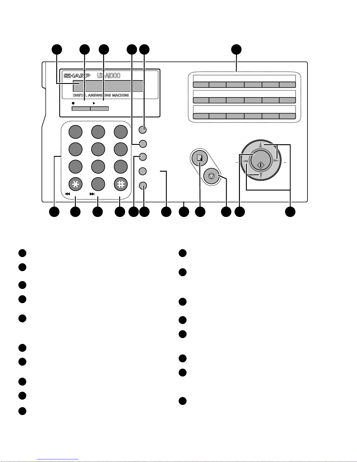
Setting the dial mode
The fax machine is set for tone dialing. If you are on a pulse dial line, you must
set the fax machine for pulse dialing. Press the panel keys as follows:
1Press once and 3 times.
2Press once and 4 times.
3Press once.
4Select the dial mode:
TONE: PULSE:
5Press to exit.
FUNCTION
12
STOP
Display:
The display briefly shows
your selection, then:
OPTION SETTING
DIAL MODE
DISTINCTIVE
1=TONE, 2=PULSE
TEL.LINE
L.SET
3
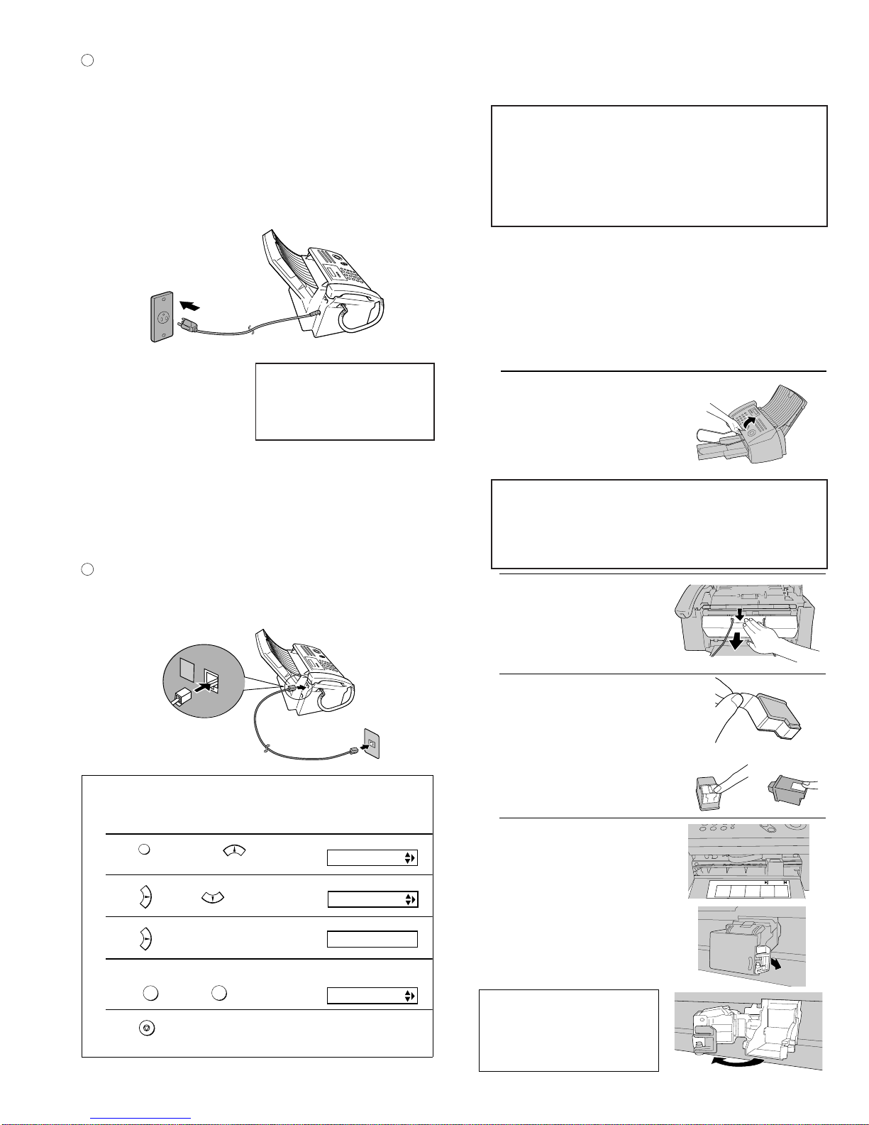
Plug the power cord into a 120 V, 60 Hz, grounded AC (3-prong)
outlet.
Caution!
• Do not plug the power cord into any other kind of outlet. This will
damage the machine and is not covered under the warranty.
•Make sure you have removed all of the packing tape before
plugging in the power cord. Plugging in the power cord
without doing so may damage the machine.
• The machine does not have a power on/off switch, so the power
is turned on and off by simply plugging in or unplugging the power
cord.
Note: If your area experiences a high incidence of lightning or
power surges, we recommend that you install surge protectors for
the power and telephonelines. Surge protectors can be purchased
at most telephone specialty stores.
“CHECK CARTRIDGE” normally
appears in the display the first
time you plug in the machine.
This message appears until you
install the print cartridge.
1Open the operation panel.
3. Installing the Print Cartridge
•
When replacing the print cartridge, be sure to use a SHARP UX-C70B
cartridge.
2Open the print compartment cover.
•Press as shown and pull the cover
toward you.
3Remove only the tape from the the new
cartridge.
•Important: Make sure you remove all
of the tape.
•CAUTION! DO NOT touch the gold
contact area of the cartridge.
4Make sure the cartridge holder is
between the "CARTRIDGE EXCHANGE
AREA" arrows on the label, and then
pull the green lever and open the
cartridge holder cover.
•If you are replacing the cartridge,
remove the old cartridge. If you are
going to use the old cartridge again,
place it in an air-tight container.
•CAUTION! DO NOT touch the contact
area inside the carriage carrier.
Note: If the print compartment cover is left
open for approximately 30 minutes with a
cartridge installed, the cartridge will
automatically return to its home position. To
make the cartridge return to the CARTRIDGE
EXCHANGE AREA when this has happened,
close the cover and then open it again.
NO GOOD NO GOOD
Caution!
Do not open the print compartment cover of the machine while it is
printing. If opened while printing, printing will stop.
Note: Keep ink cartridges sealed in their packages until you are ready
to install them. It is recommended that you do not use a cartridge that
has been left unused for a long time after opening, as the print quality
may be considerably degraded.
•Make sure the power cord of the machine is plugged in and paper is
loaded before installing or replacing the print cartridge.
If PRINTER ERROR or PRINTER ERROR/CHECK PAPER
appears...
In the event that the display shows either of the above mes-
sages, you must clear the error before installing the print
cartridge. The error can usually be cleared by opening and
closing the print compartment cover (see Step 2), or if a paper
jam has occurred, by removing the paper jam.
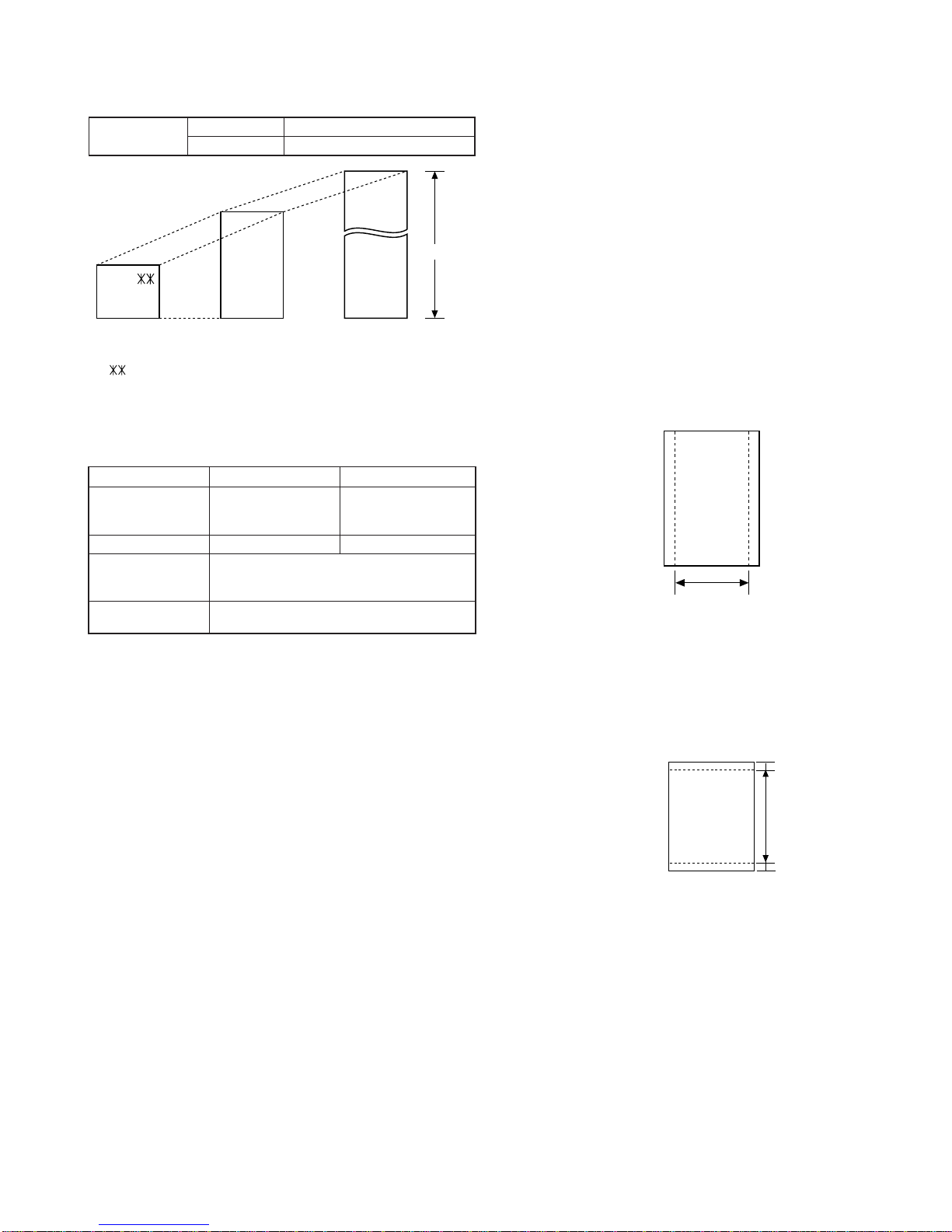
Print cartridge yield (at 4% coverage)
Initial cartridge
Ink save mode ON:Approx. 300 letter pages
Ink save mode OFF:Approx. 200 letter pages
Replacement cartridge (SHARP UX-C70B)
Ink save mode ON:Approx. 600 letter pages
Ink save mode OFF:Approx. 400 letter pages
Ink Save mode is initially turned off.

1 – 6
UX-A1000U
5Insert the new print cartridge into the
cartridge holder.
6Place your index finger on the tab as
shown and close the cartridge holder
cover with your thumb. Make sure the
cover clicks into place.
7Close the print compartment cover.
8Close the operation panel, pressing
down firmly on both front corners to
make sure it clicks into place.
Display:
1=NEW, 2=OLD
CHANGE CARTRIDGE
9Press (NEW) if the cartridge you
installed is new.
Press (OLD) if the cartridge you
installed is old.
10 Press .
If you selected "OLD" in the previous
step, this completes the installation
procedure. (Note: If you find that print
quality is not satisfactory after
reinstalling the old cartridge, align the
cartridge.)
If you selected "NEW", the display will
show the alternating messages at
right. Continue with the following steps
to align the print cartridge.
11 Press to print an alignment page. (To enter an alignment value
without printing an alignment page, press .)
1
2
1
2
1=PRINT,2=SET
ALIGN CARTRIDGE
Display when "NEW" is
selected:
OK: PRESS START
NEW CART.: OK?
Display when "1" is selected:
If you select the wrong number by mistake,
press and repeat the selection.
STOP
START/
MEMORY
12 In the alignment page that the machine prints,locate the line that comes
closest toformingacompletelystraight line.
13Press the numberkeystoenterthe numberofthe straightest line.
Example:
•If youmakeamistake,press andthenrepeattheentry.
14Press
15
STOP
Inthisexample,"15"comes
closesttoformingastraightline.ENTER(0-30)15
Afterthealignmentpageis
printed,thedisplay shows:
START/
MEMORY
.
Note: If at any time the display shows the
alternating messages at right, check the printing
paper. If the tray is empty, add paper. If there is
paper in the tray, take it out and then reinsert it.
When you are finished, press .
ADD PAPER &
PRESS START KEY
START/
MEMORY

1 – 7
UX-A1000U
4. Loading printing paper
1Pull the paper plate toward you, and
remove the paper tray cover from the
paper tray.
2If you are going to load legal paper, flip
up the paper tray extension.
3Pull the paper plate toward you and insert the stack of paper into the
tray,
PRINT SIDE UP
.
•
If paper remains in the tray, take it out and combine it into a single stack
with the new paper.
You can load letter or legal size paper in the paper tray. Recommended paper
weight is 20-lb. Copy Bond. The maximum number of sheets is as follows:
Letter size:
Approx.
200 sheets (20-Ib. copier paper at room temperature;
maximum stack height should not exceed line on tray)
Legal size: Approx. 100 sheets (20-Ib. copier paper at room temperature)
The stack
should not
be higher
than this line
Be sure to load the paper so that
printing takes place on the print side
of the paper. Printing on the reverse
side may result in poor print quality.
4Pull the paper plate toward you and
replace the paper tray cover.
Place the
coverusingthe
appropriate
notch for the
size of paper
loaded
LEGAL
LETTER
1Press once and twice.
2Press once and once.
3Press once.
4Select the paper size:
LETTER: LEGAL:
5Press to return to the date and time display.
FUNCTION
12
STOP
The display briefly shows
your selection, then:
PAPER SIZE SET
COPY CUT-OFF
1=LETTER,2=LEGAL
Display: PRINT SET-UP
The fax has been set at the factory to scale received faxes to letter size paper.
If you loaded legal paper, you must change the paper size setting to LEGAL.
1
Setting the paper size
AUTO Use AUTO for normal documents.
DARK Use DARK for faint documents.
Note: In order to transmit in SUPER FINE resolution, the receiving fax machine
must also have that resolution. If it doesn't, your machine will automatically step
down to the next best available settin
g
.
1Load the document(s).
•The document must be loaded before
the resolution and contrast can be
adjusted.
2Press one or more times
until the desired resolution and
contrast settings appear in the display.
•The first time you move through the list
of resolution settings, the contrast
setting AUTO will appear next to each
resolution setting. The second time you
move through the list, the contrast
setting DARK will appear.
RESOLUTION/
RECEPTION MODE
Display:
STANDARD :AUTO
FINE :AUTO
SUPER FINE :AUTO
HALF TONE :AUTO
STANDARD :DARK
HALF TONE :DARK
FINE :DARK
SUPER FINE :DARK
2
Contrast settings

1 – 8
UX-A1000U
1Open the operation panel.
2Open the print compartment cover.
•Press as shown and pull the cover
toward you.
3Gently pull the jammed paper out of the
machine, making sure no torn pieces
of paper remain in the print
compartment or rollers.
4Close the print compartment cover.
5Close the operation panel, pressing
down firmly on both front corners to
make sure it clicks into place.
6. Clearing jammed printing paper
If the original document doesn't feed properly during transmission or copying,
or DOCUMENT JAMMED appears in the display, first try pressing . If
the document doesn't feed out, remove it as explained below.
Important:
Do not try to remove a jammed document without releasing it as explained
below. This may damage the feeder mechanism.
1Slowly open the operation panel until it
is half open.
2Flip up the green levers on each side of
the white roller.
3Gently remove the document.
•Be careful not to tear the document.
START/
MEMORY
4Flip down the green levers on each
side of the white roller.
5Close the operation panel, pressing
down on both sides to make sure it
clicks into place.
5. Clearing a jammed document

1 – 9
UX-A1000U
[5] Quick setup guide
Plug thepowercordintoa
120-V groundedoutlet.
2.Connect thephonelinecordtothe
TEL. LINEjackandawall jack.
Attachthetrays.
1.Connect thehandset.
TEL.LINE
L.SET
1
2
Loadpaper.
Note:If you areloading legalpaper,see
page22 oftheoperationmanualto
changethepapersizesetting toLEGAL.
Pull thepaperplate
towardyou andattach
thepapertraycover.
Paperplate
1.Press asshownand
pull toopentheprint
compartment cover.
2.Removethepacking tape.3.Closetheprint
compartment cover.
Insert thepaper
printsideup.
Thestackshould
not behigher
thanthisline
Flipupifloading
legalpaper
Install thePrintCartridge.
1.Opentheoperation
panel.3.Removeonlythetape fromthenew
cartridge.
IMPORTANT:Makesureyou remove
all ofthetape.
2.Press asshownandpull toopen
theprint compartment cover.4.Makesurethecartridgeholderisbetweenthe
"CARTRIDGE EXCHANGE AREA"arrowsonthelabel,
andthenpull thegreenleverandopenthecartridge
holdercover.
6.Placeyourindexfingeronthetabandclose
thecartridgeholdercoverwith yourthumb.
Cau
NOGOOD
ART/ART/
tion!Donot touch
thegoldcontact area.
7.Closetheprint compartment cover
andthentheoperationpanel.
8.a.Press toselect NEW.
b.Press
c.Press
toprint analignment page.
1
START/
MEMORY
1
9.Inthealignment pagethat themachine
prints,locatethelinethat comesclosest
toforming acompletelystraight line.
Enterthenumberofthat line.
Example:
(If you makeamistake,press and
thenrepeat theentry.)
15
STOP
10.Press
andthen
toexit.
START/
MEMORY
STOP
1=PRINT,2=SET
ALIGNCARTRIDGE
5.Insert thenewprint cartridge
intothecartridgeholder.
Display:
1=NEW,2=OLD
CHANGE CARTRIDGE
1
2
4
6
3
5
Note: To enter your name and fax number
and set the data and time so that they
appear at the top of each fax you send, see
pages 26-29 of your operation manual.

1 – 10
UX-A1000U
[6] Quick reference guide
Place your document
(up to 20 pages) face
down in the document
feeder.
Normal
Sending Faxes Receiving Faxes
Storing Auto Dial Numbers
Recording an OGM
Dialing
1.Lift the handset or press .
2.Dial the fax number.
3.Wait for the reception tone (if a person
answers, ask them to press their Start
key).
4.Press .
Rapid Key Dialing
Press the appropriate Rapid Key.
Transmission will begin automatically.
Speed Dialing
1.Press .
2.Enter the 2-digit Speed Dial number.
3. Press .
1. Press , , and .
2. Lift the handset, press , and
speak into the handset.
3. When finished, press .
SPEAKER
START/
MEMORY
SPEED DIAL
START/
MEMORY
REC/MEMO
START/
MEMORY
STOP
Press until the arrow in the
display points to the desired reception
mode.
FAX mode: The fax machine automatically
answers and receives faxes.
TEL mode: Answer all calls (even faxes)
by picking up the handset. To begin fax
reception, press .
TAD mode: Select this mode when you go
out to receive both voice messages and
faxes.
1.Press once and once.
2.Enter a 2-digit Speed Dial number (01 to
99; 01 to 18 for Rapid Key Dialing).
3.Enter the fax number and press .
4.Enter a name by pressing number keys.
(To enter two letters in succession that
require the same key, press after
entering the first letter.)
5. Press and then .
RESOLUTION/
RECEPTION MODE
START/
MEMORY
FUNCTION
START/
MEMORY
START/
MEMORY
STOP
FAX
TEL
FAX
TEL
FAX
TAD
TAD
TAD
TEL
JAN-03 10:30
JAN-03 10:30
JAN-03 10:30
A =
B =
C =
D =
E =
F =
G =
H =
I =
J =
K =
L =
M =
N =
O =
P =
Q =
R =
S =
T =
U =
V =
W =
X =
Y =
Z =
SPACE =
RESOLUTION/
RECEPTION MODE

UX-A1000U
2 – 1
CHAPTER 2. ADJUSTMENTS
[1] Adjustments
General
Sincethefollowing adjustments and settings areprovided for this model,
make adjustments and/or setup as necessary.
1. Adjustments of output voltage (FACTORY ONLY)
1. Install the power supply unit in the machine.
2. Set the recording paper and document.
3. When the document is loaded, power is supplied to the output lines.
Confirm that outputs are within the limits below.
Output voltage settings
CNLIUA
TEL/LIU PWB CONTROL PWB
PRINTER PWB
POWER SUPPLY
PWB
PANEL PWB
1
18
18
12
11
1
1
2
1
2
27
28
27
28
12
12
12
CNLIUA CNPRT
CNPRINT
CNPN
CNPN
CNPW
CNPW
1 +24V
2DG
3 MICMUTE
4 TELIN
5 TELMUTE
6 RXIN
7 TELOUT
8 TXOUT
9 CML
10 CI–
11 HS–
12 RHS–
Connector
No. CNLIUA
Pin No.
1 +30V
2 +30V
3MG
4MG
5DG
6DG
7 +5V
8 +5V
Connector
No. CNPW
Pin No.
Output Voltage limits
+5V 4.75V ~ 5.25V
+30V 27.0V ~ 33.0V
1 KEN4A
2 KEN3A
3 KEN2A
4 KEN1A
5DG
6 +3.3V
7E
8 SEN0
9 SEN1
10 SEN2
11 SEN3
12 SEN4
Connector
No. CNPN
Pin No. 1 +30V
3 +30V
5 +3.3VP
7 +3.3VP
9 PD0
11 PD1
13 PD2
15 PD3
17 PD4
19 PD5
21 PD6
23 PD7
25 nSTROBE
27 PRTRES
Connector
No.
Pin No. 2MG
4MG
6DG
8DG
10 nACK
12 BUSY
14 PERROR
16 nFAULT
18 SELECT
20 nSELECTIN
22 nINIT
24 nAUTOFD
26 PIN
28 SN_Cover
2 – 1
CNPRINT CNPRT

UX-A1000U
2 – 2
4. Volume adjustment
You can adjust the volume of the speaker, handset, and ringer using the
UP and DOWN keys.
(1) Speaker
1. Press the SPEAKER key.
2. Press the UP or DOWN key until the display shows the desired vol-
ume level.
• Press SPEAKER key again to turn off the speaker.
(2) Handset
1. When talking through the handset, press UP or DOWN until the
display shows the desired volume level.
Display:
RECEIVER: HIGH
RECEIVER: MIDDLE
RECEIVER: LOW
(3) Ringer
1. Press the UP or DOWN key. (Make sure SPEAKER key has not been
pressed, the handset is not lifted, and a document is not loaded in the
feeder.)
Display:
RINGER: HIGH
RINGER: MIDDLE
RINGER: LOW
RINGER OFF: OK?
2.Ifyouselected RINGER OFF: OK?, to turnofftheringer, press START/
MEMORY key.
3. Settings
(1) Dial mode selector
DIAL mode (Soft Switch No. SW-B4 DATA No. 3)
(step 1) Select "OPTION SETTING".
KEY : FUNCTION
DISPLAY: OPTION SETTING FINE PRIORITY
(step 2) Select "DIAL MODE".
KEY: Push until DIAL MODE is
indicated because the number of
's changes by the model.
DISPLAY: DIAL MODE 1=TONE, 2=PULSE
(step 3) Select, using "1" or "2".
KEY: 1
DISPLAY: TONE SELECTED
KEY: 2
DISPLAY: PULSE SELECTED
(step 4) End, using the "STOP" key.
KEY:
STOP
2. IC protectors replacement
ICPs (IC Protectors) are installed to protect the motor driver circuit.
ICPsprotect various ICs andelectronic circuits from anovercurrent con-
dition.
The location of ICPs are shown below:
CONTROL PWB
PRINTER PWB
CNPRT CNPRINT
FU1
FU101
CNPN CNPW
CNMT
FU100
(BOTTOM SIDE)
(TOP SIDE)
(1)FU100 (QFS-L1026YCZZ) is installed in order to protect IC’s from
anover-current generated in the motordrive circuit. If FU100is open,
replace it with a new one.
(2)FU101 (QFS-L2016XHZZ) is installed in order to protect IC’s from
an over-current generated in the LIU or CIS control circuit. If FU101
is open, replace it with a new one.
(3)FU1 (QFS-L1027YCZZ) is installed in order to protect IC’s from an
over-current generated in the motor drive circuit. If FU1 is open, re-
place it with a new one.
2 – 2
↔
↔
• Note: The volume reverts to
MIDDLE each time you
replace the handset.
↔
↔
↔
• Theringer will ring once at the
selected level.

UX-A1000U
2 – 3
2. Diagnostic items
1 Rapid 1 SOFT SWITCH MODE Soft switches are displayed and changed. List can be output.
2 Rapid 2 ROM & RAM CHECK ROM is sum-checked, and RAM is matched. Result list is output.
3 Rapid 3 AGING MODE 10 sheets of check patterns are output every 5 minutes per sheet.
4 Rapid 4 PANEL KEY TEST Panel keys are tested. Result list is output.
5 Rapid 5 CHECK PATTERN Check pattern is output.
6 Rapid 6 SIGNALS SEND MODE Various signals of FAX communication are output.
7 Rapid 7 MEMORY CLEAR Back-up memory is cleared, and is set at delivery.
8 Rapid 8 SHADING MODE Shading compensation is performed in this mode.
9 Rapid 9 AUTO FEEDER MODE Insertion and discharge of document are tested.
10 Rapid 10 ENTRY DATA SEND Registered content is sent.
11 Rapid 11 ENTRY DATA RECEIVE Registered content is received, and its list is output.
12 Rapid 12 FLASH MEMORY CHECK Checks flash memory write/read.
13 Rapid 13 FLASH MEMORY CLEAR Checks flash memory clearing.
[2] Diagnostics and service soft switch
1. Operating procedure
(1) Entering the diagnostic mode
Press FUNC →9 →→ 8 →# →7 , and the following display will appear.
TC02 / TA71 After 2 sec: DIAG MODE
contorol PWB ROM
TC02
printer PWB ROM
TA71
Then press the START key. Select the desired item with the up key or the down key or select with the rapid key. Enter the mode with the START key.
(Diag•specifications)
If the diag mode cannot be set, repeat the diag mode operation, per-
forming the following operation.
After the power is turned on and "WAITA MOMENT" is indicated, press
the STOP key. In relation with the process response (request from Production
Engineering)"WAITAMOMENT"clockindicationmay appear depending
onSTOPkeytiming.Ifthe STOPkeyishelddown, "MEMORYCLEAR?"
appears.
FUNC DIAG MODE
TC02 /TA71
9 8 7
STARTSoft switch mode
Rapid2
Rapid1
ROM & RAM check
Rapid3
Aging mode
Rapid4
Panel key test
Rapid5
Check pattern
Rapid6
Signals send mode Shading mode
Rapid11
Rapid10
Rapid9 Auto feeder mode
Entry data send
Entry data receive
START
Rapid8
START
KEY
STOP
KEY
+
"Power ON"
Memory clear
Rapid7
START
START
START
START
START
START
Rapid12 Flash memory check
START
Rapid13 Flash memory clear
START
START
START
START
START
START/
MEMORY
ITEM No. Contents Function
Rapid No.
2 – 3

UX-A1000U
2 – 4
3. Diagnostic items description
3. 1. Soft switch mode
Used to change the soft switch settings.
The soft switch which is stored internally is set by using the keys.
The available soft switches are SW-A1 to SW-P7.
The content of soft switches is shown in Soft switch description.
The contents are set to factory default settings.
3. 2. ROM & RAM check
ROM executes the sum check, and RAM executes the matching test.
The result will be notified with the number of short sounds of the buzzer
as well as by printing the ROM & RAM check list.
Number of short sounds of buzzer 0 →No error
1 → FAX engine ROM error
2 → Printer engine ROM error
3 → RAM error
(4Kbytes SRAM or 2Mbytes DRAM or Printer 512bytes NV-RAM)
3. 3. Aging mode
If any document is present, copying will be executed sheet by sheet. If
nodocument is present, thecheck pattern will beprinted sheet by sheet.
This operation will be executed at a rate of one sheet per 5 minutes, and
will be ended at a total of 10 sheets.
3. 4. Panel key test
This mode is used to check whether each key operates properly. Press
the key on the operation panel, and the key will be displayed on the
LCD. Therefore, press all keys.At this time, finally press the STOP key.
WhentheSTOPkeyispressed,thekeysthatarenotjudgedas"pressed"
will be printed on the result list.
• LED part of the contact image sensor (CIS) is kept on during the term
from when "START" of the panel test mode to end with the STOP key.
3. 5. Check pattern
Check patterns are printed on one sheet.
Printing performance:The following 4 items are checked.
• Print area:Checks that the print area is reserved.
• Nozzles:Whencheckingthenozzle,makesure at least 1
lineisprinted
in each block: all the blocks of horizontal black bars and the black line
patterns in
B
and
C
(
B
:16 patterns,
C
:13 patterns).
(Note: If the nozzle
A
is not spraying properly, checking the area
B
and
C
may be difficult (or may not be printed at all). In this case,
print again.
• Vertical align:Checks that the straight vertical line is drawn instead of
crooked line.
• Skew:Checks the skew of the recording paper.
Detailed of check patterns
1
Top skew
2
Nozzle test
3
Vertical lines
4
Bottom skew
5
Top margin
6
Left margin
7
Bottom margin
3. 6. Signals send mode
This mode is used to send various signals to the circuit during FAX com-
munication. Every push of START key sends a signal in the following
sequence.Moreover, thesignalsound is also output to the speakerwhen
the line monitor of the soft switch is on.
[1] No signals [8] 9600BPS (V.29)
[2] 14400BPS (V.33) [9] 7200BPS (V.29)
[3] 12000BPS (V.33) [10] 4800BPS (V.27ter)
[4] 14400BPS (V.17) [11] 2400BPS (V.27ter)
[5] 12000BPS (V.17) [12] 300BPS (FLAG)
[6] 9600BPS (V.17) [13] 2100Hz (CED)
[7] 7200BPS (V.17) [14] 1100Hz (CNG)
3. 7. Memory clear
This mode is used to clear the backup memory and reset to the default
settings.
3. 8. Shading mode
The mode is used for the shading com-pensation. For reading, set up
the special original paper. (Refer to page 8-6)
The compensation memorizes the reference data of white and black for
reading.Moreover, the memorized data is not erased even if memory
clear mode is executed.
3. 9. Auto feeder mode
In this mode, a document is inserted and discharged to check the auto
feed function. After this mode is started, set a document, and the docu-
ment feed will be automatically tested.
3. 10. Entry data send
This mode is used to send the registered data to another machine and
make the other machine copy the registered content.
Before sending in this mode, it is necessary to set the other machine at
the entry data receive mode.
The following, information will be send to the remote machine:
1. Telephone list data
2. Sender register data
3. Optional setting data
4. Soft switch content
5. Junk fax number
6. Recording setting list data
3. 11. Entry data receive
In this mode, the registered data sent from the other machine is receiv-
ed and the received data is registered in the machine. When this mode
is used for receiving, the other machine must be in the entry data send
mode.
After receiving is completed, the following lists are printed.
1. Telephone list data
2. Sender register list (*)
3. Optional setting list (*)
4. Soft switch content
5. Junk fax number list (*)
6. Recording setting list data (*)
(*): Refer to SETUP LIST
3. 12. Flash memory check
Data is written into and read from the flash memory to check data con-
formity. When the unit enters this mode, the check is started.
3. 13. Flash memory clear
Data in the flash memory is cleared (memory clear). When the unit en-
ters this mode, the check is started.
*Operation of hardware and signal in the flash memory check mode and
flash memory clear mode, and the result of check.
The result is announced by the buzzer beeps. The result of check is
printed.
Beeps
0 →No error
1 →Memory error
0 1 2 3 4 5 6 7 8 9 10 11 12 13 14 15 16 17 18 19 20 21 22 23 24 25 26 27 28 29 30
7
5
A
B
C
61
2
3
4
2 – 4

UX-A1000U
2 – 5
4. Entering the printer diagnostic mode
Press FUNC →9 →→ 8 →# →6 , and the following display will appear.
PRINT DIAG MODE
Then press the START key. Select the desired item with the up key or the down key or select with the rapid key. Enter the mode with the START key.
(Diag•specifications)
If the diagnostic mode cannot be set, repeat the diagnostic mode operation, performing the following operation.
After the power is turned on and "WAITA MOMENT" is indicated, press the STOP key.
In relation with the process response (request from Production
Engineering)"WAITAMOMENT"clockindicationmay appear depending
onSTOPkeytiming.Ifthe STOPkeyishelddown, "MEMORYCLEAR?"
appears.
FUNC
PRINT DIAG MODE
9 8 6
START4% DATA PRINT AGING
Rapid2
Rapid1
ASF AGING
Rapid3
ASF SKEW CHECK AGING
Rapid4
CROSS PATTERN
Rapid5
INITIAL CARTRIDGE DATA SETTING
Rapid6
Rapid7
PRINTER DOWNLOAD
START
START
KEY
STOP
KEY
+
"Power ON"
START
START
START
START
START
IJP LIST MODE START
Rapid8PRINTER ERROR CHECK MODE START
START/
MEMORY
6. Printer diagnostic items description
6. 1. 4% data print aging
This mode is the aging mode that prints the text pattern of 4%
6. 2. ASF aging (all white)
This mode is the aging mode that tests the performance of the ASF function.
6. 3. ASF skew check aging
This mode is the aging mode that tests the performance of the ASF function.
Detailed of check patterns
1. Top skew
2. Bottom skew
3. Top margin
4. Bottom margin
6. 4. Cross pattern
Thismodeprints the test pattern thattests the performance of theprinter.
6. 5. Initial cartridge data setting
This mode makes the dot counter the setting for initial cartridge,
And this mode resets the following counter.
1. Replacement counter of the cartridge
2. Paper jam counter
6. 6. Printer download
This mode rewrites the software of the printer engine.
5. Printer diagnostic items
1 Rapid 1 4% DATA PRINT AGING 4% of printing data continue to be printed.
2 Rapid 2 ASF AGING The feed of the paper is continued.
3 Rapid 3 ASF SKEW CHECK AGING The frame pattern continues to be printed to check the inclination performance.
4 Rapid 4 CROSS PATTERN The image data of the cross pattern to be printed.
5 Rapid 5
INITIAL CARTRIDGE DATA SETTING
It makes the dot counter the setting for the initial cartridge.
6 Rapid 6 PRINTER DOWNLOAD This mode rewrites the software of the printer engine.
7 Rapid 7 IJP LIST MODE The maintenance data is printed.
8 Rapid 8
PRINTER ERROR CHECK MODE
The cause of “PRINTER ERROR” message is displayed.
ITEM No. Contents Function
Rapid No.
2 – 5

UX-A1000U
2 – 6
6. 7. IJP list mode
Maintenance data of the printer is output.
[Details of maintenance data]
Item Clear timing Updata timing
Dot counter At the replacement cartidge After printing
Page counter At the replacement cartidge After printing
Number of head cleaning (Wiping of cartridge) At the initial cartridge setting At the maintenance
Replacement counter of the cartridge At the initial cartridge setting At the replacement of cartridge
Jam counter At the initial cartridge setting At every paper jam
6. 8. Printer error check mode
The cause of “PRINTER ERROR” message is displayed.
[Details of Display]
Display Cause of “PRINTER ERROR” message
PRINTER ERR 01 Power on reset response was not received from printer.
PRINTER ERR 02 Printer interface ASIC data buffer was full and not resume for 180sec.
PRINTER ERR 03 Carrier was not reached to cap position for 15sec after cover closed.
PRINTER ERR 04 NPA command was not forwarded to printer for 5sec.
PRINTER ERR 05 Printer interface ASIC command buffer error was occurred during NPA command forwarding.
PRINTER ERR 06 NPA response was not received for 5sec.
PRINTER ERR 07 Printer interface ASIC response buffer error was occurred during NPA response receiving.
PRINTER ERR 08 ESC* command was not forwarded to printer for 5sec.
PRINTER ERR 09 Printer interface ASIC command buffer error was occurred during ESC* command forwarding.
PRINTER ERR 10 Print data transfer from Printer interface ASIC to printer was not completed for 180sec.
PRINTER ERR 11 Last printed page was not exited for 60sec.
PRINTER ERR 12 Carrier was not reached to cap position for 60sec after last printed page was exited.
PRINTER ERR 13 Alignment pattern or Clean nozzles pattern printing was not completed for 60sec.
PRINTER ERR 14 Printer interface ASIC print data bit error was occurred.
PRINTER ERR 15 Printer interface ASIC print data DRAM writing error was occurred.
PRINTER ERR 21 Reserved
PRINTER ERR 22 Reserved
PRINTER ERR 23 Reserved
PRINTER ERR 24 Carrier stall error
PRINTER ERR 25 Printer PWB NVRAM error
PRINTER ERR 26 Printer could not output print data.
PRINTER ERR 27 Printer head short error
PRINTER ERR 31 Received NPA response was not for "Loop Back" command.
PRINTER ERR 32 Received NPA response was not for "Register For DSA" command.
PRINTER ERR 33 Received NPA response was not for "Print Head Information" command.
PRINTER ERR 34 Received NPA response was not for "Set Alignment Data" command.
PRINTER ERR 35 Received NPA response was not for "Get Printer Firmware Version" command.
PRINTER ERR 36 Received NPA response was not for "Printer ROM & RAM Check" command.
PRINTER ERR 37 Received NPA response was not for "Printer ROM Checksum" command.
PRINTER ERR 38 Received NPA response was not for "Cartridge Initial" command.
PRINTER ERR 39 Received NPA response was not for "Default Cartridge" command.
PRINTER ERR 40 Received NPA response was not for "Reset Wipe Count" command.
PRINTER ERR 41 Received NPA response was not for "Reset Page Count" command.
PRINTER ERR 51 Invalid command parameters was forwarded to printer.
PRINTER ERR 52 No supported command was forwarded to printer.
PRINTER ERR 53 Forwarded command was rejected by printer.
2 – 6

UX-A1000U
2 – 7
Press FUNCTION 9 8 7 STARTSTART
Press FUNCTION key.
Press key.
Press key.
Bit1 - 8 are set.
Soft SW-A2 - SW-P7 are set.
S F T SW-A1 = 1 0 0 0 0 0 0 0
S F T SW-A2 = 0 0 0 0 0 0 0 0
S F T SW-P7 = 0 0 0 0 0 0 0 0
Press key during setting.
To finish the settings halfway between
SW-A1 and SW-P7, press the STOP
key. In this case, the setting being done
to the SW No. on display will be nullified
while settings done to the preceding
SW No. remain in effect.
The soft switch mode is terminated.
S F T SW-A1 = 0 0 0 0 0 0 0 0
START
DATA No. 1 2 3 4 5 6 7 8
When the COPY key is pressed, the
contents of soft switches are printed.
7. How to make soft switch setting
To enter the soft switch mode, press the following key entries in se-
quence.
2 – 7

UX-A1000U
2 – 82 – 8
8. Soft switch description
• Soft switch
1 Protect from echo No Yes 0
2 Forced 4800 BPS reception Yes No 0
3 Footer print Yes No 0
4 Length limitation of copy/send/receive No limit Copy/send: 60cm 0
Receive: 1m
5 CSI transmission No transmitted Transmitted 0
6 DIS receive acknowledgement during G3 Twice NSF: Once 0
transmission DIS: Twice
7 Non-modulated carrier for V29 transmission Yes No 0
mode
8 EOL (End Of Line) detect timer 25 sec 13 sec 0
Modem speed V.33 V.17 V.29 V.27 ter
14400 12000 14400 12000 9600 7200 9600 7200 4800 2400
1 0011110000 1
2 1100000000 0
3 0101010110 0
4 0000111100 0
5 Sender’s information transmit No Yes 0
6 Reserved 0
7 Communication error treatment in RTN No communication error Communication error 0
sending mode (Reception)
8 CNG transmission No Yes 0
CED tone signal interval 1000ms 750ms 500ms 75ms
1 No. 1 1 1 0 0 0
2 No. 2 1 0 1 0 0
3 MR coding No Yes 0
4 ECM mode No Yes 0 OPTION
5 ECM MMR mode No Yes 0
6 Reserved 0
7 Reserved 0
8 Reserved 0
1 Signal transmission level Binary input 0
2 No. = 16 8 4 2 1 1
3 1 2 3 4 5 0
4 EX 0 1 0 0 0 0
5 eg. Signal transmission level is set to –8dBm. 0
6 Protocol monitor (Error print)
Printed at communication. error
Not printed 0
7 Protocol monitor Yes No 0
8 Line monitor Yes No 0
Digital line equalization setting (Reception) 7.2km 3.6km 1.8km 0km
1 No. 1 1 1 0 0 1
2 No. 2 1 0 1 0 1
Digital line equalization setting 7.2km 3.6km 1.8km 0km
3 (Transmission) No. 3 1 1 0 0 0
4 No. 4 1 0 1 0 0
Digital cable equalizer setting (Reception 7.2km 0km
5 for Caller ID) No. 5 1 0 0
6 No. 6 1 0 0
7 Error criterion 10 ~ 20 % 5 ~ 10 % 0
8 Anti junk fax check Yes No 1
SW
NO. DATA
NO. ITEM Switch setting and function
10Remarks
Initial
setting
SW
l
A1
SW
l
A2
SW
l
A3
SW
l
A5
SW
l
A4
Other manuals for UX-A1000
1
Table of contents
Other Sharp Fax Machine manuals