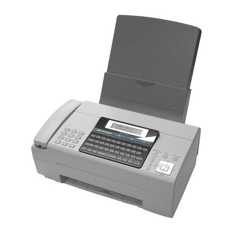
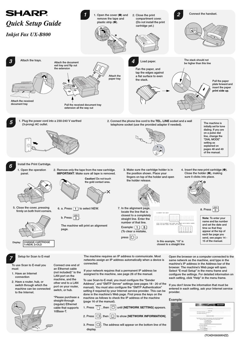
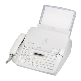
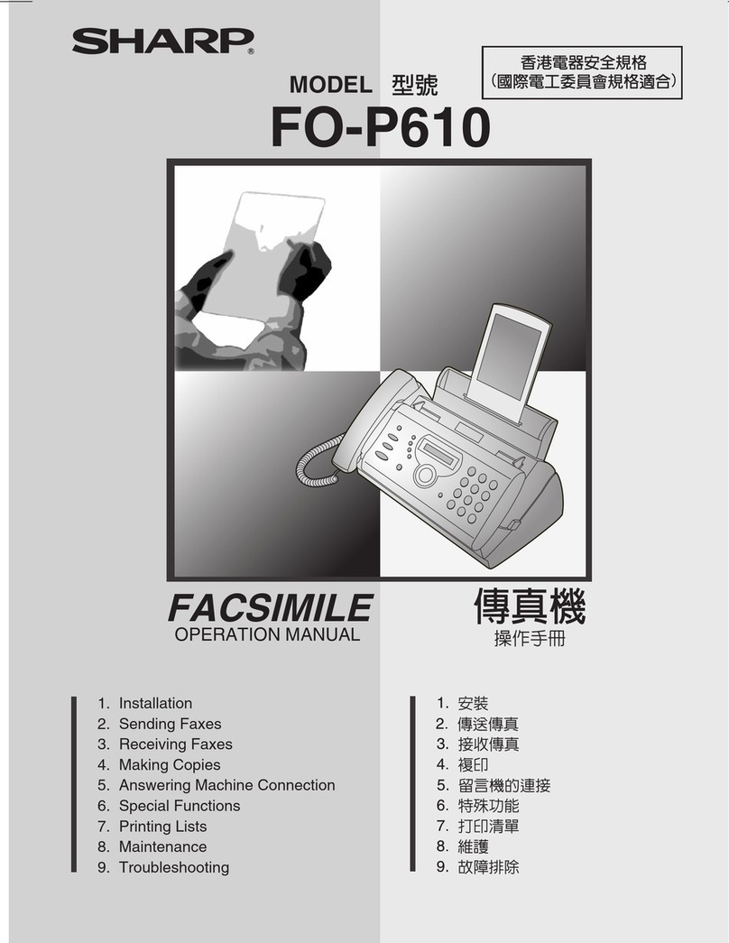
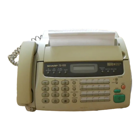
Sharp FO-2600 User manual

OPERATION MANUAL
FACSIMILE
MODEL
FO-2600
QUICK REFERENCE GUIDE
1. INSTALLATION
2. INITIAL SETTINGS
3. BASIC OPERATIONS
4. ANSWERING MACHINE CONNECTION
5. SPECIAL FUNCTIONS
6. OPTIONAL SETTINGS
7.
PRINTING OUT REPORTS AND LISTS
8. MAINTENANCE
9. TROUBLESHOOTING
SPECIFICATIONS

MAINS PLUG WIRING INSTRUCTIONS
This equipment is fitted with a moulded type mains plug which incorporates a detachable fuse cover,
under no circumstances should the plug be used without the fuse cover fitted.
In the unlikely event of the socket outlet inyour home not being compatible with the plug supplied, cut
off the mains plug and fit an appropriate type observing the wiring code below.
DANGER: The fuse from the cut-off plug should be removed and the plug should be disposed of in a
safe manner. Under no circumstances should the cut-off plug be inserted into a socket outlet as a
serious electric shock may occur.
If you are not sure how to do this, get help from a qualified electrician.
IMPORTANT
The wires in this mains lead are coloured in accordance with the following code:
GREEN-AND-YELLOW: Earth
BLUE: Neutral
BROWN: Live
As the colours of the wires in the mains lead of this apparatus may not correspond with the coloured
markings identifying the terminals in your plug, proceed as follows:
ThewirewhichiscolouredGREEN-AND-YELLOWmustbeconnectedtotheterminalintheplugwhich
is marked by the letter E, or by the safety earth symbol , or coloured green or green-and-yellow.
The wire which is coloured BLUE must be connected to the terminal which is marked with the letter N
or coloured black.
The wire which is coloured BROWN must be connectedto the terminal which is marked with the letter
Lor coloured red.
This apparatus must be protected by a 13A fuse in the mains plug or distribution board.
"WARNING: THIS APPARATUS MUST BE EARTHED"
This equipment complies with the requirements of Directives 89/336/EEC and 73/23/EEC as amended by 93/68/EEC.
Dieses Gerät entspricht den Anforderungen der EG-Richtlinien 89/336/EWG und 73/23/EWG mit Änderung 93/68/EWG.
Ce matériel répond aux exigences contenues dans les directives 89/336/CEE et 73/23/CEE modifiées par la directive
93/68/CEE.
Dit apparaat voldoet aan de eisen van de richtlijnen 89/336/EEG en 73/23/EEG, gewijzigd door 93/68/EEG.
Dette udstyr overholder kravene i direktiv nr. 89/336/EEC og 73/23/EEC med tillæg nr. 93/68/EEC.
Quest’ apparecchio è conforme ai requisiti delle direttive 89/336/EEC e 73/23/EEC, come emendata dalla direttiva
93/68/EEC.
Este equipamento obedece àsexigências dasdirectivas 89/336/CEE e 73/23/CEE, na sua versão corrigidapela directiva
93/68/CEE.
Este aparato satisface lasexigenciasdelas Directivas89/336/CEE y73/23/CEE,modificadas por medio de la 93/68/CEE.
Denna utrustning uppfyller kraven enligt riktlinjerna 89/336/EEC och 73/23/EEC så som kompletteras av 93/68/EEC.
Dette produktet oppfyller betingelsene i direktivene 89/336/EEC og 73/23/EEC i endringen 93/68/EEC.
Tämä laite täyttää direktiivien 89/336/EEC ja 73/23/EEC vaatimukset, joita on muutettu direktiivillä 93/68/EEC.
89/336/EEC : EMC directive 73/23/EEC : Low voltade directive 93/68/EEC : CE Mark regulation

QUICK REFERENCE GUIDE
Note:
Steps which are optional are enclosed in a dotted frame:
Transmitting documents
Normal Dialling
Direct Keypad
Dialling
Rapid Key Dialling
Speed Dialling
Redialling
RESOLUTION
SPEED
RESOLUTION
RESOLUTION
RESOLUTION
REDIAL
START
START
START
START
→→
→
→
→
→
→
→
→
→
→
→
→
→
→
→
→
→
→
Load
document
Lift handset
or
press SPEAKER Dial (press
numeric keys)
Wait for
reception tone Hang up
Load
document Dial (press
numeric keys)
Load
document Press Rapid
Key
Load
document Enter Speed Dial
number (press 2
numeric keys)
Load
document Wait for
reception tone
RESOLUTION
Making voice calls
Normal Dialling
Rapid Key Dialling
Speed Dialling
Redialling
SPEED
REDIAL
→→
→
→→
→→
→
Lift handset
or
press SPEAKER Dial (press
numeric keys) Lift handset if you
pressed SPEAKER
Press SPEAKER Press Rapid
Key Lift handset if you
pressed SPEAKER
Lift handset
or
press SPEAKER
Enter Speed Dial number
(press 2 numeric keys) Lift handset if you
pressed SPEAKER
Lift handset
Function Guidance List
To print out a guide to all of the functions which are accessed by pressing the
FUNCTION key, press the FUNCTION key and then the START key.
QUICK REFERENCE GUIDE Quick-i

ABOUT THE MERCURY RESIDENTIAL SERVICE
132 or Residential PIN Service
Residential 132 Service
Access code 132 is pre-programmed in the
Mercury key (Rapid key 01) at the factory
Simply prefix all numbers manually or auto-
matically dialled with this key. The key can
also be used to assign the Mercury access
code as a prefix to other autodial numbers
during programming (page 29).
Residential PIN Code Service
Clear access code 132 from the Mercury
key (Rapid key 01) (page 23).
Program the Mercury key (Rapid key 01)
withaccesscode131,apause,andMercury
PIN (page 27).
Simply prefix all numbers manually or auto-
matically dialled with this key. The key can
also be used to assign the Mercury PIN asa
prefix to other autodial numbers during pro-
gramming (page 29).
Tochange from the Residential PINCode Serviceto the Residential 132 Service, clearthe
Mercury key (Rapid key 01) and reprogram it with the access code 132. The machine will
automatically recognise the digits 132 and accept them without requiring a further pause
or Mercury PIN.
QUICK REFERENCE GUIDE
Quick-ii QUICK REFERENCE GUIDE

INTRODUCTION
Thank you for purchasing the FO-2600! In addition to providing you with the ease and
convenience of plain-paper printing, the FO-2600 features a variety of special
functions designed to increase the range and power of your communications.
This manual gives you easy-to-follow instructions for installing and using your new fax.
The Table of Contents will show you where instructions for using each feature are
located. Whilst you may not need to read every section in detail at first, we
recommend that you at least look over them briefly.
If you have any questions or problems which cannot be solved by reading this manual,
please contact your Sharp dealer.
♦Keys, switches, and labels on the machine are indicated in BOLD print.
♦Messages appearing in the display are indicated in CAPITAL LETTERS.
♦
Your fax machine and the telephone system
Your Sharp FO-2600 Facsimile Transceiver is approved for connection to the Public
Switched Telephone Network (PSTN), it is also approved for connection via a Private
Branch Exchange (PBX), and can be used with either Loop Disconnect (LD) or Dual
Tone Multi-Frequency (DTMF) signalling.
Your facsimile machine is not suitable as an extension to some payphones or for use
on shared service lines.
REN
The Ringer Equivalence Number (REN) of your fax machine is 1.
The total number of instruments that can be connected to an exclusive line is
determined by adding the REN values of each instrument. The total should not exceed
4.0. A telephone provided by BT is assumed to have a REN of 1 unless otherwise
marked.
Satisfactory ringer operation can not be guaranteed in installations consisting of mixed
apparatus types, even if the REN value does not exceed 4.
i

Emergency services
Emergency services (999) can be called from this apparatus. Please display on the
telephone the number required to access that service, together with the number of the
telephone, using the label provided.
♦
Private branch exchange (PBX) connection
Your facsimile machine is approved for connection to the Public Telephone Network
(PSTN) via compatible PBX systems. Consult your supplier for a list of suitable PBX
systems. It cannot be guaranteed that this facsimile machine will operate correctly
under all possible conditions of connection to compatible PBX systems.
This facsimile machine has been approved for use of the following facilities:
Simple telephone
Tone dialling (DTMF)
Loop disconnect (Pulse dialling)
Memory dialling
Loudspeaking (Call Progress Monitor)
On-hook dialling
Automatic answering
Automatic dialling
Automatic clearing
Last number redial
Time break or Earth recall
Series connection of extension telephone(s)
Any other usage will invalidate the approval of the facsimile if as a result it then ceases
to comply with the standards against which approval was granted.
Series connection
When connected via series apparatus, difficulties may occasionally be experienced
when making calls to the PSTN and by both parties during telephone conversations. If
difficulties are experienced, contact the supplieror maintainer of the series apparatus
in the first instance.
While operation may be possible initially, changes to or modernisation of the network
taking place in the normal course of events may result in the facsimile equipment being
connected to a network service with which it was not designed to be compatible.
Failure of the facsimile / series apparatus to work under these circumstances may not
be the fault of the network operator.
The voltage drop introduced by your facsimile between the PSTN and the associated
apparatus at a current of 40mA d.c. is 2 volts, therefore no additional series equipment
may be connected.
INTRODUCTION
ii

TABLE OF CONTENTS
QUICK REFERENCE GUIDE
1 INSTALLATION
UNPACKING . . . . . . . . . . . . . . . . . . . . . . . . . . . . . . . . . . . . . 1-1
INSTALLING THE PRINTER CARTRIDGES . . . . . . . . . . . . . . . . . . . . 1-2
ASSEMBLY AND CONNECTIONS . . . . . . . . . . . . . . . . . . . . . . . . . 1-6
LOADING PRINTING PAPER . . . . . . . . . . . . . . . . . . . . . . . . . . . . 1-10
2 INITIAL SETTINGS
A LOOK AT THE OPERATION PANEL . . . . . . . . . . . . . . . . . . . . . . . 2-1
ENTERING YOUR NAME AND FAX NUMBER . . . . . . . . . . . . . . . . . . . 2-2
ENTERING LETTERS FOR NAMES . . . . . . . . . . . . . . . . . . . . . . . . . 2-3
SETTING THE DATE AND TIME . . . . . . . . . . . . . . . . . . . . . . . . . . 2-5
SELECTING THE RECEPTION MODE . . . . . . . . . . . . . . . . . . . . . . . 2-6
STORING NUMBERS FOR AUTOMATIC DIALLING . . . . . . . . . . . . . . . . 2-7
USING THE MERCURY FUNCTION . . . . . . . . . . . . . . . . . . . . . . . . 2-11
3 BASIC OPERATIONS
SENDING DOCUMENTS . . . . . . . . . . . . . . . . . . . . . . . . . . . . . . 3-1
RECEIVING DOCUMENTS . . . . . . . . . . . . . . . . . . . . . . . . . . . . . 3-11
MAKING COPIES . . . . . . . . . . . . . . . . . . . . . . . . . . . . . . . . . . 3-14
MAKING TELEPHONE CALLS . . . . . . . . . . . . . . . . . . . . . . . . . . . 3-16
4 ANSWERING MACHINE CONNECTION
USING THE CONNECTION . . . . . . . . . . . . . . . . . . . . . . . . . . . . . 4-1
OPTIONAL A.M. MODE SETTINGS . . . . . . . . . . . . . . . . . . . . . . . . . 4-5
5 SPECIAL FUNCTIONS
MEMORY . . . . . . . . . . . . . . . . . . . . . . . . . . . . . . . . . . . . . . . 5-1
TRANSMISSION RESERVATION . . . . . . . . . . . . . . . . . . . . . . . . . . 5-3
BROADCASTING . . . . . . . . . . . . . . . . . . . . . . . . . . . . . . . . . . 5-4
CONFIDENTIAL TRANSMISSION . . . . . . . . . . . . . . . . . . . . . . . . . . 5-6
POLLING . . . . . . . . . . . . . . . . . . . . . . . . . . . . . . . . . . . . . . . 5-7
RELAY REQUEST . . . . . . . . . . . . . . . . . . . . . . . . . . . . . . . . . . 5-10
TIMER OPERATIONS . . . . . . . . . . . . . . . . . . . . . . . . . . . . . . . . 5-13
ENTERING AND USING PROGRAMS . . . . . . . . . . . . . . . . . . . . . . . 5-16
ANTI JUNK FAX . . . . . . . . . . . . . . . . . . . . . . . . . . . . . . . . . . . 5-22
6 OPTIONAL SETTINGS
7 PRINTING OUT REPORTS AND LISTS
8 MAINTENANCE
9 TROUBLESHOOTING
PROBLEMS AND SOLUTIONS . . . . . . . . . . . . . . . . . . . . . . . . . . . 9-1
MESSAGES AND SIGNALS . . . . . . . . . . . . . . . . . . . . . . . . . . . . . 9-3
CLEARING PAPER JAMS . . . . . . . . . . . . . . . . . . . . . . . . . . . . . . 9-5
SPECIFICATIONS
iii

Notes
TABLE OF CONTENTS
iv

1 INSTALLATION
UNPACKING
Take the fax machine out of the box carefully, and remove all packing material. Make
sure you have all the items listed below. If any are missing, contact your dealer.
Handset
Handset lead
Telephone line cord
Paper tray cover
Rapid key labels
Operation manual
Paper tray
Original document
support
Received document
support
Imaging cartridge
Drum cartridge
Mercury
application set
British Telecom fax
book card
Precautions before setting up
♦The fax must be installed on a level surface.
♦Keep the fax away from air conditioners, heaters, direct sunlight, and dust.
♦Provide easy access to the front, back, and sides of the fax. In particular, keep the
area in front of the fax clear, or the original document may jam as it comes out after
scanning.
♦Keep liquids away from the fax. Liquids spilled on the fax can damage the internal
circuitry.
♦If the fax is moved from a cold to a warm place, it is possible that condensation may
form on the reading glass, preventing proper scanning of documents for
transmission. To remove the condensation, turn on the power and wait
approximately 2 hours before using the fax.
INSTALLATION 1-1

INSTALLING THE PRINTER CARTRIDGES
The laser printer in your fax creates printed text and images by applying toner to the
page with a photoconductive drum. Follow the steps below to install or replace the
imaging cartridge (which contains the toner) and the drum cartridge.
1Pull the release on the right side of
the operation panel forward, and open
the operation panel.
2Grasp the top of the received
document guide and pull it so that it
rotates toward you. Lift the guide
straight up and out of the printing
compartment.
•• If you are installing the cartridges for
the first time, go to Step 5.
3If you are replacing the cartridges,
grasp the finger hold on the imaging
cartridge handle (marked "PUSH")
and pull the handle out. Rehold the
handle, and pull the imaging cartridge
out of the compartment.
•• Caution! The fusing unit (the black
unit with ribs extending across the
bottom of the compartment) becomes
very hot during printing. Be careful not
to touch it.
•• If you are only replacing the drum
cartridge, place the imaging cartridge
on a piece of paper on a horizontal
surface. Make sure that the cartridge
lies flat.
•• If you are only replacing the imaging
cartridge, go to Step 8.
1-2 INSTALLATION

4Grasp the two finger holds on the blue
section of the drum cartridge, and pull
it out of the compartment.
5Unfold the end of the drum cartridge
bag, and remove the new drum
cartridge.
•• Do not use a sharp object to cut the
bag.
•• Do not remove the sheet of black
protective paper yet.
6Grasp the two finger holds on the
blue section of the drum cartridge,
and insert it into the compartment.
Make sure it fits into place on top of
the roller in the bottom of the
compartment.
•• If you have removed a used drum
cartridge, place it in the empty drum
cartridge bag, seal the bag, and
dispose of it in a way that conforms to
any local regulations that may exist in
your area.
7Grasp the protruding end of the
protective paper, and pull the paper
out of the cartridge.
•• Be sure not to leave any pieces of torn
paper in the printing compartment.
•• If you are not replacing the imaging
cartridge, go to Step 10.
INSTALLING THE PRINTER CARTRIDGES
INSTALLATION 1-3

8Remove the imaging cartridge from its
bag, and shake it 4 or 5 times in a
horizontal direction.
•• This ensures that the toner is well
distributed inside the cartridge.
9Remove the white cover.
•• Remove the white cover and pull out
the black rubber strip which is attached
to the white cover.
10 Grasp the handle of the imaging
cartridge so that the stamped
markings are facing upwards, and
insert the cartridge into the printing
compartment.
11 Place your thumb on the centre of the
handle where it is marked "PUSH",
and push the handle slightly up and
in so that the cartridge fits into place.
•• If you have removed a used imaging
cartridge, place it in the empty imaging
cartridge bag, seal the bag, and
dispose of it in a way that conforms to
any local regulations that may exist in
your area.
12 Hold the received document guide
vertically, and insert it into its
compartment so that the tabs on each
side of the guide go into the slots on
the sides of the compartment.
PUSH
INSTALLING THE PRINTER CARTRIDGES
1-4 INSTALLATION

13 Make sure that the received
document guide is positioned so that
the arm on the left side of the guide
will go into the hole. Place your
thumbs on both sides of the guide
where it is marked "PUSH", and push
the guide forward until it fits into
place.
14 Close the operation panel.
Replacing the cartridges
Your fax uses the following imaging cartridge and drum cartridge. These can be
obtained from your dealer or retailer.
FO-26DC IMAGING CARTRIDGE
FO-26DR DRUM CARTRIDGE
The imaging cartridge is capable of printing approximately 2000 pages if A4 size
paper is used and 4% of each page is covered with toner. When the cartridge nears
empty (about 250 pages can still be printed), the &indicator on the operation panel
will begin to blink. When the cartridge is empty, the indicator will light steadily and
TONER EMPTY will appear in the display. Replace the cartridge as described above.
To assure printing quality, we recommend that you replace the drum cartridge after
20,000 pages have been printed. You can check the total number of pages printed in
the display by pressing the FUNCTION key and then the "#" key.
P
U
S
H
PUSH
INSTALLING THE PRINTER CARTRIDGES
INSTALLATION 1-5

ASSEMBLY AND CONNECTIONS
Handset
Connect the handset lead to the
handset and the fax as shown.
•• The ends of the handset lead are
identical, so they will go into either
socket.
Place the handset on the handset rest.
Use the handset to make ordinary
phone calls, or to transmit and
receive documents manually.
Power lead
Plug the power lead into a 230 V,
50 Hz, grounded (3-prong) AC outlet.
•• Important: Whenever you unplug the
power lead, disconnect the fax
machine from the telephone network
first.
•• Caution: The mains outlet
(socket-outlet) shall be installed near
the equipment and shall be easily
accessible.
Press the power switch to turn on the
power.
Telephone line cord
Plug one end of the telephone line
cord into the socket on the fax marked
"TEL. LINE". Plug the other end into a
standard telephone wall socket.
•• Be sure to plug the line cord into the
TEL. LINE socket on the fax. Do not
plug it into the TEL. SET socket.
•• Note: Connection to the telephone
network must not be hard wired.
TEL.
SET TEL.
LINE
1-6 INSTALLATION

Comments:
••
Your fax is set for tone dialling. If you are on a pulse only dial line, you must reset it for
pulse dialling by changing Option Setting 19. This procedure is described in Chapter 6,
"Optional Settings".
••
A new plan telephone socket must be located near the machine. If you don’t have one,
contact your local telephone supplier.
••
Your fax cannot be used on a key system without the necessary adaptation of the system.
Please consult the installers of the system if this is required.
••
If you intend to use a computer fax modem on the same phone line, you must reset Option
Setting 12 to NO in order to prevent transmission and reception errors. This procedure is
described in Chapter 6, "Optional Settings".
••
If you are connectiong the fax to a PBX, you may need to reset the fax to the appropriate
recall mode for the PBX. This is done by Option Setting 21 as described in Chapter 6.
••
If your area experiences a high incidence of lightning or power surges, we recommend that
you install surge protectors for the power and telephone lines. Surge protectors can be
purchased from your dealer or at most telephone specialty stores.
••
The facsimile will not ring in response to incoming calls in the absence of mains power to
the machine. For this reason it is recommended that the fax is not left as the only telephone
instrument connected to the line when in this state to avoid the loss of voice calls.
••
Your fax is still capable of making outgoing telephone calls when the power is switched
OFF, however, the dialling method will default to pulse in this condition. The
*
key may be
used to switch to tone dial mode.
START
Volume settings
Adjust the volume of the speaker for on-hook dialling as follows:
1Press the FUNCTION key and then
the SPEAKER key.
2Press the "#" key to turn the volume
up, or the "*" key to turn it down.
3Press the START key.
or
To adjust the volume of the ringer, reset Option Setting 22 as described in Chapter 6,
"Optional Settings".
SPEAKER
FUNCTION
ASSEMBLY AND CONNECTIONS
INSTALLATION 1-7

Trays
Attach the paper tray by inserting the
tabs into the holes at the rear of the
fax.
Place the paper cover on the paper tray
so that the notches on each side of the
cover fit onto thecatches on each side
of the tray.
Attach the original document support
and the received document support to
the top of the fax as shown.
Original document
support
Received document
support
ASSEMBLY AND CONNECTIONS
1-8 INSTALLATION

Other devices
If desired, you can connect either an answering machine or an extension telephone to
your fax.
♦Connecting an answering machine to the fax will allow you to receive both voice and
fax messages on the same line while you are out. For details on using this feature,
see Chapter 4.
♦You can connect an extension phone to the fax to make and receive calls like any
other extension phone on your line. For details on receiving faxes from an extension
phone, see "Receiving Documents" in Chapter 3.
Remove the seal covering the socket
marked "EXT. TEL." on the fax.
Insert the modular plug of the
extension phone or answering
machine line into the U.K. style socket
marked "EXT. TEL." as shown.
•• Important: If the extension telephone
or answering machine is not connected
to the extension telephone socket on
the fax as shown, the set-up will not
operate properly.
•• Eire : Remove the seal covering the
socket marked "TEL. SET" on the fax.
Insert the plug of the extension
telephone or the answering machine
line directly into the "TEL.SET" socket.
tel
line telphone
Comments:
••
The safety status of this socket is TNV, and is provided for the connection of approved
telephone equipment only. To ensure continued safety compliance, do not connect any
other equipment to this socket.
••
More than one extension telephone may be connected to the same line as the fax, provided
they are connected as shown above and the total REN value does not exceed 4. If you are
connecting the fax into an existing multi-telephone installation, the wiring may need some
alteration. Contact your telephone supplier for assistance.
Important: If you are connecting an answering
machine, make sure the other end of the line is
inserted into the answering machine’s
telephone line socket, not its telephone socket.
ASSEMBLY AND CONNECTIONS
INSTALLATION 1-9

LOADING PRINTING PAPER
The paper tray holds the paper on which received documents and copies are printed.
Up to 100 sheets of A4 size paper from 60 to 90 g/m2can be loaded in the tray.
Caution!
••
Do not use paper which has already been printed on one side by a laser printer or copier.
This may damage the roller in the fusing unit, causing poor printing quality and frequent
paper jams.
Note:
Plain paper has a "print" side which should be used to obtain the best print quality. The
print side is not visible to the naked eye, so check the label on the end of the package
before removing the paper. The print side will be indicated by an arrow, symbol, or
wording. Load the paper in the tray print side up as described below.
1Remove the paper tray cover.
2Fan the paper, and then tap the edge
against a flat surface to even the
stack.
3Pull the lever on the right side of the
paper tray (marked "PULL") toward
you.
4Insert the paper into the tray, print
side up.
1-10 INSTALLATION

5Make sure that the right edge of the
paper is aligned against the right
paper guide, and then move the left
paper guide until it fits into the
position marked "A4".
•• To move the guide, pinch the lever
against the guide.
6Push the lever on the right side of the
paper tray down to set the paper.
7Replace the paper tray cover.
••
When adding paper to the paper tray, you must first take out any remaining paper, combine it
into one stack with the new paper, and then put the stack in the tray. If you do not remove the
remaining paper and simply place new paper on top of it, double feeding may result.
LOADING PRINTING PAPER
INSTALLATION 1-11

Notes
LOADING PRINTING PAPER
1-12 INSTALLATION
Other manuals for FO-2600
2
Table of contents
Other Sharp Fax Machine manuals
Popular Fax Machine manuals by other brands

Panasonic
Panasonic KX-F560 operating instructions

Panasonic
Panasonic UF 890 - Panafax B/W Laser operating instructions

Olivetti
Olivetti d-Copia 3202MF Operation guide

Panasonic
Panasonic UF-6950 - Panafax - Multifunction Network guide

Panasonic
Panasonic KX-FLB751E operating instructions

NEC
NEC NEFAX 805 Operation manual