Sharp FO-70 User manual

FO-50RA
FO-70RA
No. 00ZFO50RA/SME
CHAPTER 1. GENERAL DESCRIPTION
[1] Specifications ............................................ 1-1
[2] Operation panel......................................... 1-2
[3]Transmittabledocuments .......................... 1-3
[4] Installation ................................................. 1-4
[5] Quick reference guide ............................... 1-9
CHAPTER 2. ADJUSTMENTS
[1] Adjustments .............................................. 2-1
[2] Diagnostics and service soft switch .......... 2-2
[3]Troubleshooting ...................................... 2-18
[4] Error code table....................................... 2-19
CHAPTER 3. MECHANISM BLOCKS
[1] General description ................................... 3-1
[2] Disassembly and assembly
procedures ....................................... 3-3
CHAPTER 4. DIAGRAMS
[1] Block diagram ............................................4-1
[2] Wiring diagram .......................................... 4-2
[3] Point-to-point diagram ............................... 4-3
CHAPTER 5. CIRCUIT DESCRIPTION
[1] Circuit description ..................................... 5-1
[2] Circuit description of control PWB ............ 5-2
[3] Circuit description of TEL/LIU PWB .......... 5-9
[4] Circuit description of
power supply PWB............................5-12
[5] Circuit description of CIS unit...................5-12
CHAPTER 6. CIRCUIT SCHEMATICS AND
PARTS LAYOUT
[1] Control PWB circuit ................................... 6-1
[2] TEL/LIU PWB circuit.................................. 6-9
[3] Power supply PWB circuit ...................... 6-13
[4] Operation panel PWB circuit ................... 6-15
CHAPTER 7. OPERATION FLOWCHART
[1] Protocol ..................................................... 7-1
[2] Power on sequence................................... 7-2
CHAPTER 8. OTHERS
[1] Service tools ............................................. 8-1
[2] IC signal name .......................................... 8-4
PARTS GUIDE
CONTENTS
FACSIMILE
Parts marked with " " are important for maintaining the safety of the set. Be sure to replace these parts with specified ones for
maintaining the safety and performance of the set.
This document has been published to be used
for after sales service only.
The contents are subject to change without notice.
SHARP CORPORATION
SERVICE MANUAL
Illustration: FO-50
Non cutter model Cutter model
FO-50 FO-70
FO-50
MODEL FO-70

FO-50RA
FO-70RA
(Danish) ADVARSEL !
Lithiumbatteri-Eksplosionsfare ved fejlagtig håndtering.
Udskiftning må kun ske med batteri af samme fabrikat og type.
Levér det brugte batteri tilbage til leverandoren.
(English) Caution !
Danger of explosion if battery is incorrectly replaced.
Replace only with the same or equivalent type
recommended by the equipment manufacturer.
Discard used batteries according to manufacturer’s
instructions.
(Finnish) VAROITUS
Paristo voi räjähtää, jos se on virheellisesti asennettu.
Vaihda paristo ainoastaan laitevalmistajan suosittelemaan
tyyppiin. Hävitä käytetty paristo valmistajan ohjeiden
mukaisesti.
(French) ATTENTION
Il y a danger d’explosion s’ il y a remplacement incorrect
de la batterie. Remplacer uniquement avec une batterie du
même type ou d’un type recommandé par le constructeur.
Mettre au rébut les batteries usagées conformément aux
instructions du fabricant.
(Swedish) VARNING
Explosionsfare vid felaktigt batteribyte.
Använd samma batterityp eller en ekvivalent
typ som rekommenderas av apparattillverkaren.
Kassera använt batteri enligt fabrikantens
instruktion.
(German) Achtung
Explosionsgefahr bei Verwendung inkorrekter Batterien.
Als Ersatzbatterien dürfen nur Batterien vom gleichen Typ oder
vom Hersteller empfohlene Batterien verwendet werden.
Entsorgung der gebrauchten Batterien nur nach den vom
Hersteller angegebenen Anweisungen.
CAUTION FOR BATTERY REPLACEMENT

1 – 1
FO-50RA
FO-70RA
CHAPTER 1. GENERAL DESCRIPTION
[1] Specifications
Automatic dialing: Rapid Key Dialing: 5 numbers
Speed Dialing: 35 numbers
Fax paper: Initial starter roll (included with machine):
10 m
Recommended replacement roll:
FO-20PRw, 30m
Paper cutting method: FO-50: Tear off by hand
FO-70: Automatic cutter
Modem speed: 9600 bps with automatic fallback to lower
speeds
Transmission time* : Approx. 15 seconds
Resolution: Horizontal: 8 dots/mm
Vertical:
Standard: 3.85 lines/mm
Fine/Halftone: 7.7 lines/mm
Super fine: 15.4 lines/mm
Automatic document feeder: 5 pages max. (20 lb paper)
Halftone (grayscale): 64 levels
Display: 16-digit LCD display
Compression scheme: MR, MH, Sharp (H2)
Applicable telephone line: Public switched telephone network
Compatibility: ITU-T (CCITT) G3 mode
Input document size: Automatic feeding:
Width: 148 to 216 mm
Length: 140 to 297 mm
Manual feeding:
Width: 148 to 216 mm
Length: 140 to 600 mm
Effective scanning width: 210 mm max.
Effective printing width: 210 mm max.
Contrast control: Automatic/Dark selectable
Reception modes: Fax, Tel, Fax/Tel,A.M.
Copy function: Yes
Telephone function: Yes (cannot be used if power fails)
Power requirements: 220-240 VAC, 50/60 Hz
Operating temperature: 5 - 35°C
Humidity: Maximum: 85 % RH
Power consumption: Standby: 2.3 W
Maximum: 115 W
Dimensions: Width: 304 mm
Depth: 236 mm
Height: 122 mm
Weight: Approx. 2.6 kg
* Basedon ITU-T (CCITT)TestChart #1 at standard resolution in Sharp
special mode, excluding time for protocol signals (i.e., ITU-T phase C
time only).
Note: The facsimile machine is Year 2000 compliant.
As a part of our policy of continuous improvement, SHARP reserves the right to make design and specification changes for procduct
improvement without prior notice. The performance specifications figures indicated are nominal values of production units. There may be some
deviation from these values in individual units.

1 – 2
FO-50RA
FO-70RA
[2] Operation panel
1. Rapid Dial keys
Press one of these keys to dial a fax number automatically.
2. Display
This displays messages and prompts during operation and
programming.
3. FUNCTION key
Press this key to select various special functions.
4. VOLUME keys
Press this keys to adjust the volume of the speaker when
the SPEAKER key has been pressed, the volume of the
ringer at all other times.
5. Number keys
Use these keys to dial numbers, and enter numbers and
letters when storing auto-dial numbers.
6. SPEED DIAL key
Press this key to dial a fax or voice number using an
abbreviated 2-digit Speed Dial number.
7. REDIAL key
Press this key to automatically redial the last number
dialed.
8. START key
Press this key to begin transmission when using Speed
Dialing, Direct Keypad Dialing, or Normal Dialing.
9. STOP key
Press this key to cancel operation before it is completed.
10. COPY/HELP key
When a document is in the feeder, press this key to make
a copy of a document. At any other time, press this key to
print out the Help List, a quick reference guide to the
opeation of your fax machine.
11. RESOLUTION/RECEPTION MODE key
When a document is in the feeder, press this key to adjust
the resolution for faxing or copying. At any other time,
press this key to select the reception mode (an arrow in the
display will point to the currently selected reception mode).
12. SPEAKER key
Press this key to listen the line and fax tones through the
speaker when faxing a document.
Note: This is not a speakerphone. You must pick up the
handset to talk with the other party.
13. HOLD/SEARCH key
Press this key to search for an auto-dial number, or, during a
phone conversation, press this key to put the other party on
hold.
14. Panel release
Grasp this finger hold and pull toward you to open the
operation panel.
TEL FAX
RECEPTION
MODE RESOLUTIONFUNCTION
DOWN VOLUME UP
A.M.
SPEED DIAL
REDIAL
SPEAKER
01 02
03 04
05 06
07 08
09 10/POLL
ABC DEF
JKL MNO
GHI
TUV WXYZ
PQRS
START
STOP
COPY/HELP
HOLD/SEARCH
TEL FAX
GHI
PQRS
JKL
ABC DEF
MNO
WXYZ
TUV
ABCDE/
STOP
COPY/
HELP
START
FUNCTION
VOLUME
SPEED
DIAL
REDIAL
HOLD/
SEARCH
SPEAKER
RESOLUTION/
RECEPTION MODE
123
654
789
0
2
TEL/FAX A.M.
POLL
8
1 4 5 62 3 7
11109 12 1314

1 – 3
FO-50RA
FO-70RA
[3] Transmittable documents
1. Document Sizes
* With special sizes, only one sheet can be fed into the machine at a
time. Insert next page into feeder as current page is being scanned.
2. Paper Thickness & Weight
Normal size width 148 – 216 mm
length 140 – 297 mm
5. Automatic Document Feeder Capacity
Number of pages that can be placed into the feeder at anytime is as
follows:
Normal size: max.ADF 5 sheets
Special size: single sheet only (manual feed)
NOTES: •Whenyouneedtosend or copy more pagesthanthefeeder
limit, place additional pages in feeder when last page in
feeder is being scanned.
•Place additional pages carefully and gently in feeder.
If force is used, double-feeding or a document jam may
result.
6. Readable Width & Length
The readable width and length of a document are slightly smaller than
the actual document size.
Note that characters or graphics outside the effective document scan-
ning range will not be read.
•Readable width
210mm, max.
•Readable length
This is the length of the document sent minus 5mm from the top and
bottom edges.
Use document carrier sheet for smaller documents.
Readable width
(Min.) (Max.)
A4 size
(Max.)
140mm
297mm 600mm
148mm 216mm
[
Normal size
]
216mm
[
Special size
]
3. Document Types
• Normal paper
Documents handwritten in pencil (No. 2 lead or softer), fountain
pen, ball-point pen, or felt-tipped pen can be transmitted.
Documents of normal contrast duplicated by a copying machine
can also be transmitted.
• Diazo copy (blue print)
Diazo copy documents of a normal contrast may be transmitted.
• Carbon copy
A carbon copy may be transmitted if its contrast is normal.
4. Cautions on Transmitting Documents
• Documentswritteninyellow,greenishyellow,orlightblueink cannot
be transmitted.
• Ink, glue, and correcting fluid on documents must be dry before
the documents can be transmitted.
• All clips, staples and pins must be removed from documents be-
fore transmission.
• Patched (taped) documents should be copied first on a copier and
then the copies used for transmission.
• All documents should be fanned before insertion into the feeder to
prevent possible double feeds.
5mm
5mm
Readable length
Paper size 148mm x 140mm ~
A4 (210mm x 297mm), Letter (216mm x 279mm)
4x6 series
(788mm x 1091mm x
1000mm sheets)
Square
meter series
Minimum Maximum Minimum Maximum
Feeder capacity 10 sheets, max.
Paper thickness (ref.)
0.06mm 0.09mm 0.06mm 0.09mm
Paper weight 45kg 69.2kg 52g/m280g/m2

1 – 4
FO-50RA
FO-70RA
7. Use of Document Carrier Sheet
A document carrier sheet must be used for the following documents.
•Those with tears.
•Those smaller than size 148mm (W) x 140mm (L).
•Carbon-backed documents
NOTE: To transmit a carbon-backed document, insert a white sheet of
paper between the carbon back of the document and the docu-
ment carrier.
•Those containing an easily separable writing substance (e.g., trac-
ing paper written on with a soft, heavy lead pencil).
NOTES: •When using the document carrier, carefully read the in-
structions written on the back.
•If the document carrier is dirty, clean it with a soft, moist
cloth, and then dry it before using for transmission.
•Do not place more than one document in the carrier at a
time.
[4] Installation
1. Site selection
Takethe following points into consideration when selecting a sitefor this
model.
ENVIRONMENT
•The machine must be installed on a level surface.
•Keep the machine away from air conditioners, heaters, direct sun-
light, and dust.
•Provide easy access to the front, back, and sides of the machine. In
particular, keep the area in front of the machine clear, or the original
document may jam as it comes out after scanning.
•The temperature should be between 5°and 35°C.
•The humidity should be between 30% and 85% (without conden-
sation).
ELECTRICITY
220-240 V, 50/60 Hz, grounded (2-prong) AC outlet.
Caution!
•Connection to a power source other than that specified will cause
damage to the equipment and is not covered under the warranty.
•Ifyourarea experiences a high incidenceoflightning or power surges,
we recommend that you install a surge protector for the power and
telephonelines.Surgeprotectorscanbe purchased at most telephone
specialty stores.
If the machine is moved from a cold to a warm place...
Condensation may form on the reading glass if machine is moved from
a cold to a warm place, this will prevent proper scanning of documents
for transmission. Turn on the power and wait approximately 2 hours be-
fore using machine.
TELEPHONE JACK
A standard telephone jack must be located near the machine.
This is the telephone jack commonly used in most homes and offices.
•Plugging the fax machine into a jack which is not telephone jack may
result in damage to the machine or your telephone system. If you do
not know what kind of jack you have, or need to have one installed,
contact the telephone company.
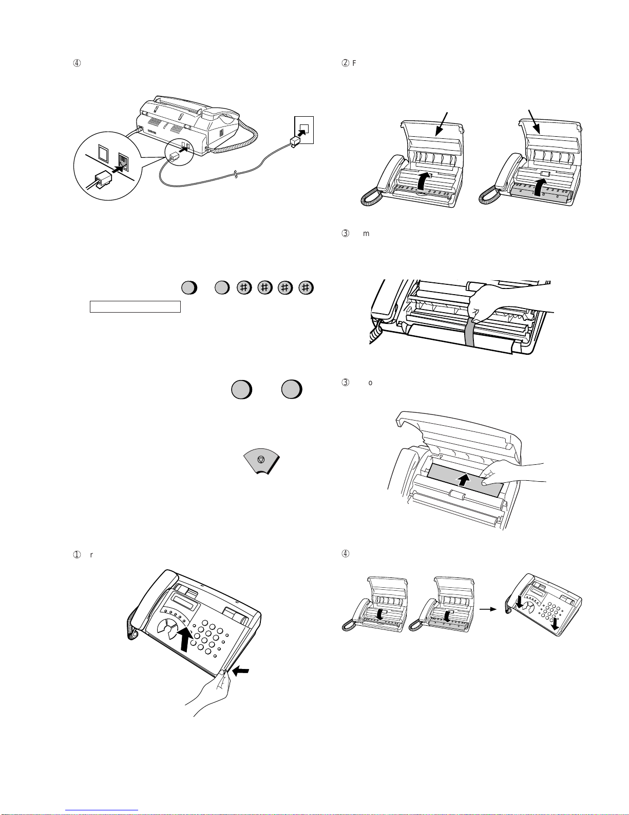
2. Assembly and connections
1
Plug the power cord into a 220-240 V, 50/60 Hz, grounded (2-prong)
AC outlet.
Caution:
The mains outlet (socket-outlet) should be installed near the equip-
ment and be easily accessable.
•Themachine does not have apower on/off switch,so the power is
turned on and off by simply plugging in or unplugging the power
cord.
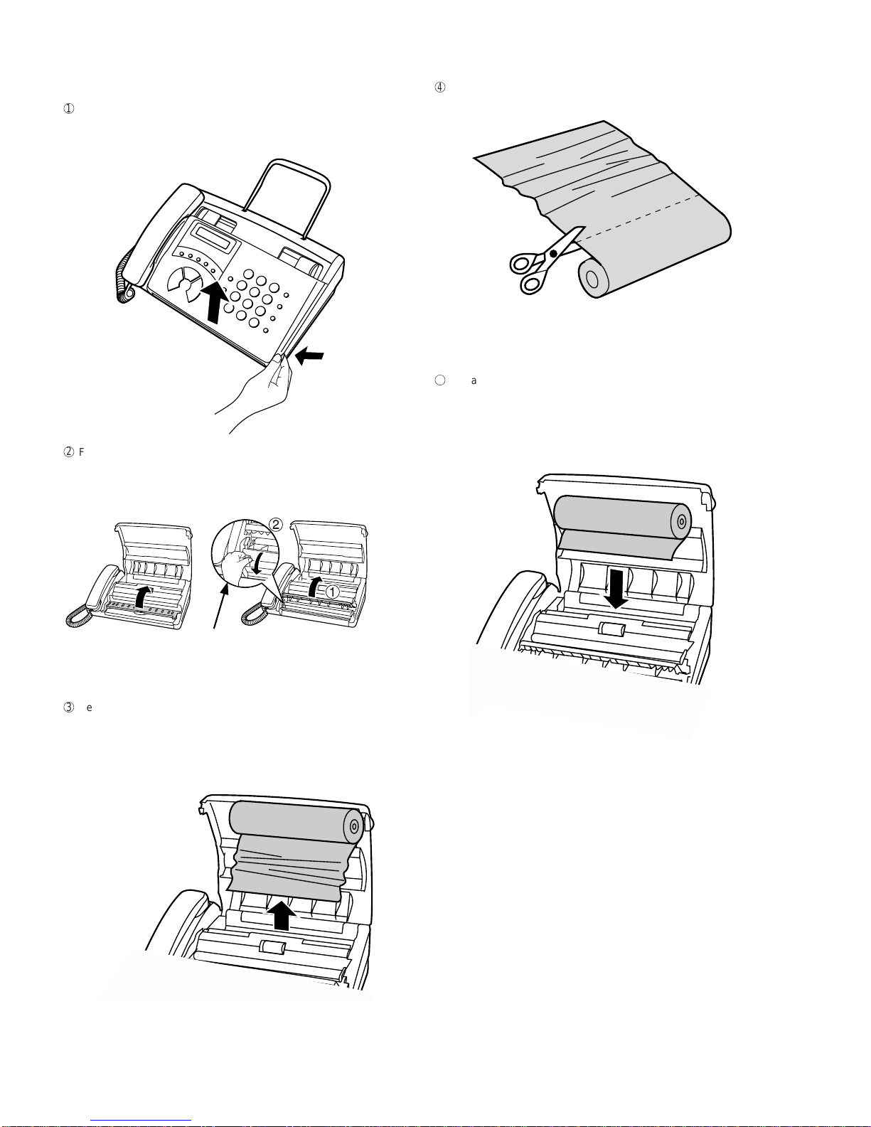
Direction of insertion
Make print straight
across paper
E.G.
Place the document
carrier in the document
feeder with the clear film
side down
Make sure the handset cord
goes into the jack marked
withahandsetsymbolon the
side of the machine!
Use the handset to make ordinary
phone calls, or to transmit and receive
faxesmanually.
2
Connect the handset as shown and place it on the handset rest.
•The ends of the handset cord are identical, so they will go into
either jack.
3
Attach the original document support as shown below.
Note: If your area experiences a high incidence of lightning or power
surges,we recommend that you installsurge protectors forthe power
and telephone lines. Surge protectors can be purchased at most tel-
ephone specialty stores.

1 – 5
FO-50RA
FO-70RA
4
Insert one end of the line cord into the socket on the back of the
machinemarkedTEL. LINE. Insert the otherendinto a wall telephone
socket.
2
Flip up the front paper guide.
FO-50 FO-70
Note: Do not peel off or
bend this strip of film.
FO-50 FO-70
TEL.
LINE
TEL.
SET
Note:The fax machine is set for tone dialing.If you areon a pulsedial
line, you must set the fax machine for pulse dialing.
Press the keys on the operation panel as follows:
2. Press 1to select tone
dialing, or 2to select pulse
dialing.
3. Press the STOP key to return to the date
and time display.
FUNCTION
4
1. Press these keys:
The display will show:
12
or
TONE PULSE
STOP
DIALMODE
3. Removing the packing paper
1
Grasp the finger hold and open the operation panel.
3
Remove the tape and packing paper from the cutter unit.
(FO-70)
3
Remove the packing paper.
(FO-50)
4
Flip down the front paper guide and then close the operation panel.

1 – 6
FO-50RA
FO-70RA
4. Loading the fax paper (FO-20PRw)
• Yourfax machine prints incoming faxeson a special kind ofpaper
called fax paper.
• Thefax machine’sprint head createstext and imagesby applying
heat to the fax paper.
1
Grasp the finger hold as shown and pull up to open the operation
panel.
2
Flip up the front paper guide.
Press the knob to make sure the
front side of the metal guide is down.
FO-50 FO-70
YES NO!
3
If you are loading paper that is 210 mm in width, place the paper roll
shims on each side of the paper compartment. (Note that Sharp rec-
ommended paper, including the initial roll, is 216 mm in width.)
• The ribbed side of the shims should face in (toward each other).
4
Unwrap the roll of fax paper and insert the paper shaft.
FO-50 FO-70
Click!
6
Insert the leading edge of the paper into the slot as shown. Continue
to push the paper through the slot until it comes out the opening in
the front of the machine.
5
Place the roll of fax paper in the compartment, making sure the ends
of the paper shaft fit into the notches on each side of the compart-
ment.
♦ Important: The roll must be placed so the leading edge of the
paper unrolls as shown. (The paper is only coated on one side for
printing. If the roll is placed backwards, the paper will come out
blank after printing.)
7
Make sure the paper comes out straight, and then flip down the pa-
per guide.
8
Close the operation panel, making sure it clicks into place.
• A short length of the paper will be cut off. (FO-70)
• A short length of the paper will feed out.
Grasp the paper by the edge and pull upward to tear it off.
(FO-50)

1 – 7
FO-50RA
FO-70RA
5. Clearing a jammed document
If the original document doesn’t feed properly during transmission or
copying,or DOCUMENT JAMMED appearsin the display,firsttry press-
ing the START key.Ifthe document doesn’tfeed out, open the operation
panel and remove it.
Important:
Do not try to remove a document without first releasing it as explained
below.
This may damage the feeder mechanism.
1
Grasp the finger hold and pull up to open the operation panel.
2
Flip up the green levers on each side of the white roller.
3
Remove the document.
4
Flip down the green levers on each side of the white roller.
5
Close the operation panel, making sure it clicks into place.
• Press down on both front corners of the panel to make sure it
clicks into place.

1 – 8
FO-50RA
FO-70RA
6. Clearing jammed paper
1
Grasp the finger hold and pull up to open the operation panel.
2
Flip up the front paper guide.
3
Remove the paper roll.
• Remove any cut pieces of paper from the paper compartment.
(FO-70 only)
Press the knob to make sure the
front side of the metal guide is down.
FO-50 FO-70
4
Cut off the wrinkled part of the paper.
5
Reload the paper.
• Jammed paper is often caused by improper loading. Be sure to
carefully follow the instructions for paper loading given in Loading
the Fax Paper.

1 – 9
FO-50RA
FO-70RA
[5] Quick reference guide
ENTERING YOUR NAMEAND NUMBER
1. Press:
FUNCTION
3
Display shows: OWN NUMBER SET
2. Press:
3. Enter your fax number (max. of 20 digits) by pressing the number keys.
•To insert a space between digits, press the # key.
•If you make a mistake, press the SPEED DIAL key to backspace and clear the
mistake.
4. Press:
5. Enter your name by pressing the appropriate number keys as shown below.
•Toentertwo lettersin successionthat requirethesame key,pressthe SPEAKER
key after entering the first letter.
SENDING FAXES
RESOLUTION/
RECEPTION MODE
FAX
TEL
FAX
TEL
05 NOV 10:30
A.M.
TEL/FAX
A.M.
TEL/FAX
05 NOV 10:30
FAX
TEL
FAX
TEL
05 NOV 10:30
A.M.
TEL/FAX
A.M.
TEL/FAX
05 NOV 10:30
START
Place your document (up to 5 pages) face
down in the document feeder.
Normal Dialing
1. Lift the handset or press
2. Dial the fax number.
3. Wait for the reception tone (if a person answers, ask them to press their Start
key).
4. Press:
Rapid Key Dialing
Press the appropriate Rapid Key. Transmission will begin automatically.
Speed Dialing
1. Press:
2. Enter 2-digit Speed Dial number.
3. Press:
RECEIVING FAXES
Press the RESOLUTION/RECEPTION MODE key until the arrow in the display
points to the desired reception mode (make sure the document feeder is empty).
SPEAKER
SPEED
DIAL
FAX mode: The fax machine automaticallyanswers on four rings andreceives the
incoming document.
TEL mode:
TEL/FAX mode: The fax machine automatically answers on 1or 2 rings and re-
ceives faxes. Voice calls (including manually dialled fax transmissions) are sig-
nalled by a special ringing sound.
A.M. mode: Select this mode when an answering machine is connected to the fax
and the answering machine is turned on.
START
START
START
SETTING THE DATE AND TIME
1. Press:
Display shows: DATE & TIME SET
2. Press:
3. Enter two digits for the Day (01 through 31).
4. Enter two digits for the Month (01 through 12).
5. Enter four digits for the Year (Ex: 2000).
6. Enter two digits for the Hour (01 through 23)
and two digits for the Minute (00 through 59).
7. When finished, press:
STORING AND CLEARING AUTO DIAL NUMBERS
1. Press:
Display shows: FAX/TEL# MODE
2. Press 1to store a number or 2to clear a number.
3. Entera 2-digit Speed Dialnumber (from 01to 05 for RapidKey Dialing, or06 to
40 for Speed Dialing) (If you are clearing a number, go to Step 7.)
4. Enter the full fax/telephone number.
5. Press:
6. Enter the name of the location by pressing number keys (Refer to the letter
entry table in
ENTERING YOUR NAMEAND NUMBER
.)
7. Press:
A =
B =
C =
D =
E =
F =
G =
H =
I =
J =
K =
L =
M =
N =
O =
P =
Q =
R =
S =
T =
U =
V =
W =
X =
Y =
Z =
SPACE =
•To change case, press the REDIAL key.
Press # or to scroll through symbols and special characters.
6. When finished, press:
START
STOP
FUNCTION
3
START
FUNCTION
3
START
STOP
START
START
STOP
Beep
START
RECEIVING

1 – 10
FO-50RA
FO-70RA
M E M O

FO-50RA
FO-70RA
CHAPTER 2. ADJUSTMENTS
[1] Adjustments
General
Sincethe following adjustmentsand settings are providedfor this model,
make adjustments and/or setup as necessary.
1. Adjustments
Adjustments of output voltage (FACTORY ONLY)
1. Install the power supply unit in the machine.
2. Set the recording paper and document.
3. When the document is loaded, power is supplied to the output lines.
Confirm that outputs are within the limits below.
Output voltage settings
3. Settings
Dial mode selector
DIAL mode (Soft Switch No. SWB4 DATANo. 2)
1DG
2 +5V
3MG
4MG
5 +24V
6 +24V
7DG
8 PSAVE
2 – 1
TEL/LIU PWB POWER SUPPLY PWB
CNL IUA CN2
CNPW
CONTROL PWB
CNL IUB
CNLIUB
CNLIUA
(step 1) Select "OPTION SETTING".
KEY : FUNCTION 4
DISPLAY: OPTION SETTING PRESS OR #
(step 2) Select "DIAL MODE".
KEY: Push # until " DIAL MODE " is
indicated because the number of
# s changes by the model.
DISPLAY: DIAL MODE
(step 3) Select, using "1" or "2".
KEY: 1
DISPLAY: TONE SELECTED
KEY: 2
DISPLAY: PULSE SELECTED
(step 4) End, using the "STOP" key.
KEY:
Cursor
When initially registering,
the mode shows 1=TONE.
When registering again, the
mode which was registered
formerly is shown.
STOP
1=TONE, 2=PULSE
Output Voltage limits
+5V 4.75V ∼ 5.25V
+24V 24.0V ∼ 26.0V
Connector
No. CNPW
Pin No.
2. IC protectors replacement
ICPs (IC Protectors) are installed to protect the motor driver circuit.
ICPsprotect various ICsand electronic circuitsfrom an overcurrent con-
dition.
The location of ICPs are shown below:
CNLIUA CNPW
CONTROL PWB
(TOP SIDE)
CNMT
FU100
CNLIUB
(1)FU100 (KAB2402) is installed in order to protect IC’s from an over-
current generated in the motor drive circuit. If FU100 is open, re-
place it with a new one.

FO-50RA
FO-70RA
[2] Diagnostics and service soft switch
1. Operating procedure
(1) Entering the diagnostic mode
Press FUNC →9 →→ 8 →# →7 , and the following display will appear.
ROM Ver. FZK0 (FZL0 ) After 2 sec: DIAG MODE
FZK0 (FO-50)
FZL0 (FO-70)
Then press the START key and country name selected by country select will appear. Select the desired item with the key or the # key or select
with the direct key. Enter the mode with the START key.
(Diag•specifications)
If the diag mode cannot be set, repeat the diag mode operation, per-
forming the following operation.
After the power is turned on and "WAITA MOMENT" is indicated, press
the STOP key.
In relation with the process response (request from Production
Engineering)"WAITAMOMENT" clock indication mayappeardepending
onSTOPkey timing. If the STOPkey is helddown, "MEMORYCLEAR?"
appears.
FUNC DIAG MODE
9 8 7
START —Soft switch mode
START AROM & RAM check
START —Aging mode
START —Panel check mode
START BCheck pattern
START CSignal send mode
START
START
KEY
STOP
KEY
+
"Power ON"
Memory clear
(Work + Backup)
FZK0
All black mode
START
START
Auto feeder mode
START
—Entry data send
START
E
Entry data receive
Cutter aging
(Cutter model only)
START
D
Shading mode
START
—
—
—
START —Memory clear
START Country select
—
FZL0
2 – 2
2. Diagnostic items
ITEM DIRECT
No. Key Contents Function
1 — SOFT SWITCH MODE Soft switches are displayed and changed. List can be output.
2 A ROM & RAM CHECK ROM is sum-checked, and RAM is matched. Result list is output.
3 — AGING MODE 10 sheets of check patterns are output every 5 minutes per sheet.
4 — PANEL CKECK MODE Panel keys are tested. Result list is output.
5 B CHECKPATTERN 2 sheets of check patterns are output.
6 C SIGNAL SEND MODE Various signals of FAX communication are output.
7 — MEMORY CLEAR Back-up memory is cleared, and is set at delivery.
8 — SHADING MODE Shading compensation is performed in this mode.
9 D ALL BLACK PRINT To check the print head, whole dots are printed over the interval of 2 m.
10 E AUTO FEEDER MODE Insertion and discharge of document are tested.
11 — ENTRY DATASEND Registered content is sent.
12 — ENTRY DATARECEIVE Registered content is received, and its list is output.
13 — CUTTER AGING Recording paper is successively cut. (Cutter model only)
14 — COUNTRY SELECT The software parameter that it agreed in each country name is set up.

FO-50RA
FO-70RA
3. Diagnostic items description
3. 1. Soft switch mode
The soft switches are provided so that each operation mode can be set
by using the operation panel.
In this mode, these switches can be checked and set.
The contents of these switches are backed up.
The available soft switches are SW-A1 to SW-K1.
The content of soft switches is shown in page 2-5 to 2-17.
The contents are set to factory default settings.
3. 2. ROM & RAM check
ROM executes the sum check, and RAM executes the matching test.
The result will be notified with the number of short sounds of the buzzer
as well as by printing the ROM & RAM check list.
Number of short sounds of buzzer 0 →No error
1 → ROM error
2 → RAM error (32Kbyte)
3. 3. Aging mode
If any documentis first present, copyingwill beexecuted sheet by sheet.
If no document is present, the check pattern will be printed sheet by
sheet. This operation will be executed at a rate of one sheet per 5min-
utes, and will be ended at a total of 10 sheets.
3. 4. Panel check mode
This mode is used to check whether each key operates properly or not.
Press the key on the operation panel, and the key will be displayed on
thedisplay.Therefore, press all keys.At this time,finally pressthe STOP
key.
When the STOP key is pressed, the keys which are not judged as
"pressed" will be printed on the result list.
• LED part of the contact image sensor (CIS) is kept on during the term
fromwhen "START"of the panel test mode to endwith the STOPkey.
3. 5. Check pattern
Thismode is usedto check thestatus of print head. Twosheets ofcheck
patternare printed. Thefollowing information of check pattern is printed.
1
Vertical stripes (alternate white and black lines) Approx. 35 mm
2
Full black Approx. 70 mm
3
Full white Approx. 35 mm
3. 6. Signal send mode
This mode is used to send various signals to the circuit during FAX com-
munication. Every push of START key sends a signal in the following
sequence.Moreover,thesignal sound isalsooutput to thespeaker when
the line monitor of the soft switch is on.
[1] No signal (CML signal turned on)
[2] 9600bps
[3] 7200bps
[4] 4800bps
[5] 2400bps
[6] 300bps (FLAG)
[7] 2100Hz (CED)
[8] 1100Hz (CNG)
[9] Pseudo Ring (models with auto TEL/FAX changeover function)
[10] END
3. 7. Memory clear
This mode is used to clear the backup memory and to reset to the fac-
tory default settings.
The content of each setting will be cleared.
Note: Be sure to execute the memory clear mode whenever you change
the country select setting. The default settings of the soft switches
varyaccording to thedestinations.Therefore,if you do not execute
the memory clear after changing the country select setting, some
functions may not work.
3. 8. Shading mode
The mode is used for the shooting compensation. For reading, set up
the special original paper.
The shooting compensation memorizes the reference data of white and
black for reading.
Moreover, the memorized data is not erased even if memory clear mode
is executed.
3. 9. All black print
This mode is used to check the state of the printing head and inten-
tionally overheat it. Whole dots are printed over the interval of 2 m. If it is
overheatedor the printing sheet isjammed, press STOPkeyforthe end.
3. 10. Auto feeder mode
In this mode, a document is inserted and discharged to check the auto
feed function.
After this mode is started, set a document, and the document feed will
be automatically tested.
3. 11. Entry data send
This mode is used to send the registered data to the other machine and
to make the other machine copy the registered content. Before sending
in this mode, it is necessary to set the other machine at the entry data
receive mode.
The contents to be sent are as follows (the machine prints each list after
the transmission has completed):
1. Telephone list data
2. Sender (cover sheet) register data
3. Optional setting content
4. Soft switch content
5. Junk fax number list
6. Country setting content
2 – 3
1
2
3
RANK 0 or 1
Note:
There is a selection RANK 0 or 1 depending on resistance value of the
thermal head. RANK 0 or RANK 1 is printed at the tail of check pattern
to identify.

FO-50RA
FO-70RA
2 – 4
Press FUNCTION 9 8 7 STARTSTART
Press FUNCTION key.
Press key.
Press key.
Bit1 - 8 are set.
Soft SW-A2 - SW-K1 are set.
S F T SW-A1 = 1 0 0 0 0 0 0 0
S F T SW-A2 = 0 0 0 0 0 0 0 0
S F T SW-K1 = 0 0 0 0 0 0 0 0
Press key during setting.
To finish the settings halfway between
SW-A1 and SW-K1, press the STOP
key. In this case, the setting being done
to the SW No. on display will be nullified
while settings done to the preceding
SW Nos. remain in effect.
The soft switch mode is terminated.
S F T SW-A1 = 0 0 0 0 0 0 0 0
START
DATA No. 1 2 3 4 5 6 7 8
When the COPY key is pressed, the
contents of soft switches are printed.
3. 12. Entry data receive
This mode is used to receive the registered data from the other machine
and to make your machine register the received data. Before receiving
in this mode, it is necessary to set the other machine at the entry data
sendmode.
After receiving is completed, the machine prints the following lists:
1. Telephone list data
2. Soft switch list
3. Junk fax number list
3. 13. Cutter aging (Cutter model only)
This mode is used to consecutively cut the recording paper about 10
mm long and to display the number of cutting times.
(The number of cutting times is cumulatively counted unless you ex-
ecute the memory clear.)
The operation is stopped in the following cases:
1. Hold down the stop key. (The cutter aging is stopped.)
2. No recording paper. (The cut operation is stopped.)
3. Recording paper jam. (The cut operation is stopped.)
3. 14. Country select
This mode is used to set line connecting parameters which correspond
to each destination.
When the country select mode is selected, and then the START key is
pressed, the destination (country name) currently set will be displayed.
By pressing the # or key, selectable destinations (country names) are
displayed. When the destination (country name) you want to choose is
displayed, press the START key. Each parameter will be stored in RAM.
Destinations (Country names) you can select are as follows:
Note: Be sure to execute the memory clear mode whenever you
change the country select setting. The default settings of the
soft switches vary according to the destinations. Therefore, if
you do not execute the memory clear after changing the coun-
try select setting, some functions may not work.
Do not set a country select setting which is different from that
of the destination of the machine. Some functions will not work
because the function and the PWB specifications are different.
4. How to make soft switch setting
To enter the soft switch mode, press the following key entries in se-
quence.
COUNTRY NAME COUNTRY NAME
HONG KONG (HK) TAIWAN (AU)
INDIA (IN) THAILAND (TH)
MALAYSIA (MY) GENERAL AREA (GRU)
RUSSIAN (RA) GENERAL AREA (GRH)
SINGAPORE (SG) AUSTRALIA (A)
SOUTH AFRICA (ZA) CHINA (CN)

FO-50RA
FO-70RA
1 Protect from echo No Yes 0
2 Forced 4800bps reception Yes No 0
3 Footer Print Yes No 0
4 Length limitation of copy/send/receive No limit Copy/Send:60cm 0
Receive:1.5m
5 CSI transmission Not transmitted Transmitted 0
6 DIS receive acknowledgement during G3 Twice NSF:Once 0
transmission DIS:Twice
7 Non modulated carrier for V29 transmission Yes No 0
mode
8 Reserved 0
Modem speed V.29 V.27 ter
9600bps 7200bps 4800bps 2400bps
1 No.1 0 0 0 0 0
2 No.2 0 0 0 0 0
3 No.3 0 1 1 0 0
4 No.4 1 1 0 0 1
5 Reserved 0
6 H2 mode No Yes 0
7 Communication error treatment in RTN No communication error Communication error 0
sending mode(Reception)
8 CNG transmission No Yes 0
CED tone signal interval 1000ms 750ms 500ms 75ms
1 No.1 1 1 0 0 0
2 No.2 1 0 1 0 0
3 MR Coding No Yes 0
4 Reserved 0
5 Reserved 0
6 Reserved 0
7 Reserved 0
8 Reserved 0
1 SignalTransmissionlevel Binary input 0
2 (0~-31 dBm setting by 1dBm step) No. = 16 8 4 2 1 1
3 1 2 3 4 5 1
4 0 1 1 0 0 0
5 0
6 Protocol monitor(Error print) Printed at com. error Not printed 0
7 Protocol monitor Yes No 0
8 Line monitor Yes No 0
Digital equalization setting(Reception) 7.2km 0km
1 No.1 1 0 1
2 No.2 1 0 1
Digital equalization setting(Transmitter) 7.2km 0km
3 No.3 1 0 0
4 No.4 1 0 0
Digital equalization setting(Reception 7.2km 0km
5 for Caller ID) No.5 1 0 0
6 No.6 1 0 0
7 Error criterion 10 ~ 20 % 5 ~ 10 % 0
8 Anti junk fax check Yes No 1
5. Soft switch description
• Soft switch
SW
NO. DATA
NO. ITEM Switch setting and function
10
SW
l
A1
SW
l
A2
SW
l
A3
2 – 5
SW
l
A4
SW
l
A5
Remarks
Initial
setting

FO-50RA
FO-70RA
1 Auto gain control(MODEM) Enable Disable 1
2 End Buzzer Yes No 1
3 Disconnect the line when DIS is received in No Yes 1
RX mode
4 Equalizer freeze control(MODEM) On Off 0
5 Equalizer freeze control 7200 bps only No Yes 0
6 CNG transmission in manual TX mode Yes No 1
7 Initial compression scheme for sharp fax in MR mode H2 mode 0
TX mode
8 Modem speed automatic down when RX Yes No 0
level is under -40dBm
EOL detect timer 5 seconds 13 seconds 20 seconds25 seconds
1 No.1 0 0 1 1 0
2 No.2 0 1 0 1 1
3 Reserved 0
4 Reserved 0
5 Reserved 0
6 Reserved 0
7 Reserved 0
8 Reserved 0
1 Hold key Enable Disable 1
2 Auto dial fax transmission by REDIAL key Yes No 0
3 Reserved 0
4 Recall interval Binary input 0
5 (0~15.5min setting by 0.5min step) No. = 16 8 4 2 1 1
6 4 5 6 7 8 0
7 0 1 0 1 0 1
8 0
1 Recall times(0~15times setting) Binary input 0
2 No.= 8 4 2 1 0
3 1 2 3 4 1
4 0 0 1 0 0
5 Dial tone detection(Before auto dial) No Yes 0
6 Reserved 0
7 Busy tone detection(After auto dial) No Yes 0
8 Busy tone detection pulse number 4 pulses 2 pulses 0
(After auto dial)
Waiting time after dialing
45 seconds 55 seconds 90 seconds 140 seconds
1 No.1 0 0 1 1 0
2 No.2 0 1 0 1 0
3 Reserved 0
4 Reserved 0
5 Reserved 0
6 Reserved 0
7 Reserved 0
8 Reserved 0
1 Dial pausing(sec/pause) 4 sec 2 sec 0
2 Dial mode Tone Pulse 0 OPTION
3 Pulse →Tone change function by key Enable Disable 1
4 Dial pulse make/break ratio(%) 40/60 33/67 1
Auto dial mode Delay timer of before line
0 second 1.5 seconds 3.0 seconds 4.5 seconds
5 connect No.5 0 0 1 1 1
6 No.6 0 1 0 1 0
7 Reserved 0
8 Reserved 0
SW
NO. DATA
NO. ITEM Switch setting and function
10
SW
l
B3
SW
l
B2
SW
l
A7
SW
l
A6
2 – 6
SW
l
B1
SW
l
B4
Remarks
Initial
setting

FO-50RA
FO-70RA
Auto dial mode Delay timer of after line 1.7s 2.0s 2.5s 3.0s 3.6s 4.0s 5.5s 7.0s
1 connect No. 1 0 0 0 0 1 1 1 1 0
2 No.2 0 0 1 1 0 0 1 1 1
3 No.3 0 1 0 1 0 1 0 1 1
4
Fax signal detection after telephone mode dial
Yes No 0
5 Reserved 0
6 Reserved 0
7 Reserved 0
8 Reserved 0
1 DTMF signal transmission level Binary input 0
2 (Low frequency 0~15.5dBm setting No.= 16 8 4 2 1 1
3 by 0.5dBm step) 1 2 3 4 5 0
4 0 1 0 1 1 1
5 1
6 Reserved 0
7 Reserved 0
8 Reserved 0
1 DTMF signal transmission level Binary input 0
2 (High frequency 0~15.5dBm setting No.= 16 8 4 2 1 0
3 by 0.5dBm step) 1 2 3 4 5 1
4 0 0 1 0 1 0
5 1
6 Reserved 0
7 Reserved 0
8 Reserved 0
Reading Slice(Binary) Factory Dark Light
Daker in
setting dark
1 No.1 0 0 1 1 0
2 No.2 0 1 0 1 0
Reading Slice(Half tone) Factory Dark Light
Daker in
setting dark
3 No.3 0 0 1 1 0
4 No.4 0 1 0 1 0
5 Line density selection Fine Standard 0
6 Reserved 0
7 MTF correction in half tone mode No Yes 0
8 Reserved 0
1 Number of rings for auto receive Binary input 0 OPTION
2 (0~15rings setting) No.= 8 4 2 1 0
3 1 2 3 4 1
4 0 0 1 0 0
5 Automatic swiching manual to auto receive Yes No 0
function
CI detect frequency
As PTT 11.5Hz 13.0Hz 20.0Hz
6 No.6 0 0 1 1 0
7 No.7 0 1 0 1 0
8 Reserved 0
2 – 7
SW
NO. DATA
NO. ITEM Switch setting and function
10
SW
l
B5
Remarks
I
nitial
setting
SW
l
B6
SW
l
B7
SW
l
C1
SW
l
D1

FO-50RA
FO-70RA
SW
NO. DATA
NO. ITEM Switch setting and function
10
2 – 8
Remarks
Initial
setting
SW
l
D2
SW
l
D3
SW
l
D4
SW
l
E1
SW
l
E2
SW
l
E3
1 Reserved 0
2 Reserved 0
3 Reserved 0
4 Reserved 0
5 Reserved 0
6 Caller ID function Yes No 0
7 Reserved 0
8 Reserved 0
1 CI off detection timer Binary input 0
2 (0~1550ms setting by 50ms step) No. = 16 8 4 2 1 1
3 1 2 3 4 5 1
4 0 1 1 1 0 1
5 0
6 Reserved 0
7 Reserved 0
8 Reserved 0
1 DTMF type Caller ID RX level Binary input 1
2 (0~-44dBm setting by 1dBm step) No.= 32 16 8 4 2 1 0
3 1 2 3 4 5 6 1
4 1 0 1 1 0 0 1
5 0
6 0
7 Reserved 0
8 Reserved 0
Pseudo ringing time at the TEL/FAX
9sec 15sec 30sec 60sec 90sec 120sec 150sec 180sec
1 automatic switching mode No. 1 0 0 0 0 1 1 1 1 0
2 No.2 0 0 1 1 0 0 1 1 1
3 No.3 0 1 0 1 0 1 0 1 0
4 Number of CNG signal detection at the Twice Once 1
TEL/FAX automatic switching mode
5 CNG detect time at TEL/FAX mode 3 sec 5 sec 0
6 Post answer tone(TEL/FAX mode) No Yes 1
7 Type of post answer tone LA-SI-DO tone 800Hz single tone 1
8 Pseudo ringer ON/OFF cycle 1 sec ON / 4 sec OFF 1 sec ON / 2 sec OFF 0
1 Pseudo ringer sound output level to the line Binary input 1
2 (0~-15dBm setting by 1dBm step) No.= 8 4 2 1 0
3 1 2 3 4 1
4 1 0 1 0 0
5 Post answer tone transmission level Binary input 1
6 (0~-15dBm setting by 1dBm step) No.= 8 4 2 1 1
7 5 6 7 8 0
8 1 1 0 0 0
1
Disconnect the line when DTMF
"
#
"
is received
Yes No 0
during TEL/FAX automatic switching mode
2 Reserved 0
3 Reserved 0
4 Reserved 0
5 Reserved 0
6 Reserved 0
7 Reserved 0
8 Reserved 0
This manual suits for next models
1
Table of contents
Other Sharp Fax Machine manuals

Sharp
Sharp UX-P410 User manual

Sharp
Sharp UX-4000M - UX 4000 B/W Laser Printer User manual

Sharp
Sharp FO-1850 User manual

Sharp
Sharp FO-D60 User manual

Sharp
Sharp FO-200 User manual

Sharp
Sharp AL-2060 User manual

Sharp
Sharp UX-51 User manual

Sharp
Sharp UX-470 User manual

Sharp
Sharp FO-4650 User manual

Sharp
Sharp UX-B700 User manual
Popular Fax Machine manuals by other brands

Panasonic
Panasonic KX-F560 operating instructions

Panasonic
Panasonic UF 890 - Panafax B/W Laser operating instructions

Olivetti
Olivetti d-Copia 3202MF Operation guide

Panasonic
Panasonic UF-6950 - Panafax - Multifunction Network guide

Panasonic
Panasonic KX-FLB751E operating instructions

NEC
NEC NEFAX 805 Operation manual