FO-DC635U
1 – 4
[3] Operation panel
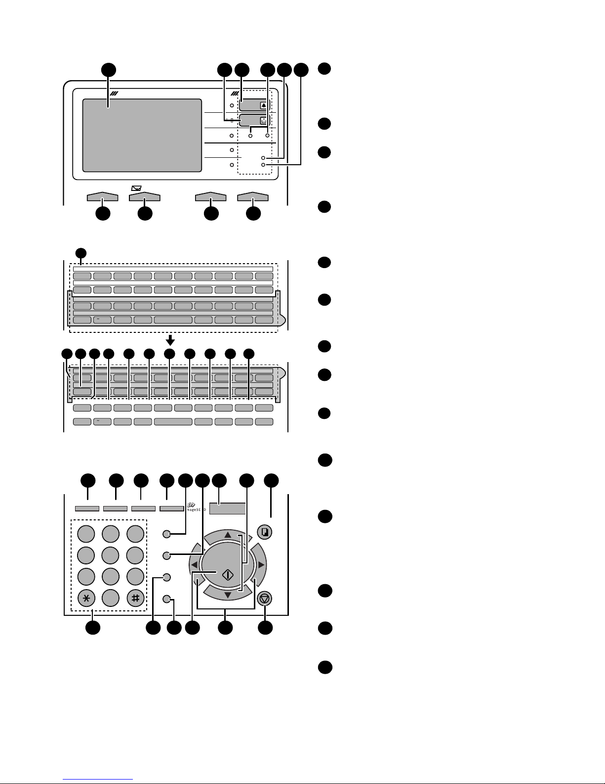
Display
This displays messages and prompts to help you operate
the machine. The backlight turns on whenever a key is
touched, and then automatically turns off after a preset time
if no further operations are performed. The display can be
tilted to the desired angle for easy viewing.
TONER indicator
This blinks when the toner cartridge nears empty, and lights
steadily when the toner cartridge needs replacement.
ALARM indicator
This blinks when one of the paper sources is empty, or the
drum cartridge is near or at the end of its life. This lights
steadily when all paper sources are empty, the print
compartment cover is open, or a paper jam has occurred.
A message will appear in the display to indicate the problem.
1
2
3
Q/! W/" E/# R/$ T/% Y/& U/' I/( O/) P/=
SYMBOL
A/|S D F G/{ H/} J/[ K/] L/+
Caps Lock
Z/< X/> C V B N/* M/? @ .com
SHIFT /^ // \ ;/: Space _- ./, DEL
Q/! W/" E/# R/$ T/% Y/& U/' I/( O/) P/=
SYMBOL
A/|S D F G/{ H/} J/[ K/] L/+
Caps Lock
PAGE COUNTER
CONFIDENTIAL
TIMER
COVER SHEET
LIFE
MEM.STATUS
REPORT
DOCUMENT
Z/< X/> C V B N/* M/? @ .com
SHIFT /^ // \ ;/: Space _- ./, DEL
01 02 03 04 05 06 07 08 09 10
11 12 13 14 15 16 17 18 19 20
40 41 42 43 44 45 46 47 48 49
50 51 52 53 54 55 56 57 58 59
21 22 23 24 25 26 27 28 29 30
31 32 33 34 35 36 37 38 39
11
11
14 15 16 17 18 19 2012 13
DATAlight
This blinks when the machine is receiving a print job over
the network (only when the network printer option is
installed).
FAX1 / FAX2 lights
When the dual line option is installed, FAX 1 lights when
Line 1 is being used and FAX 2 lights when Line 2 is being
used. When the dual line option is not installed, only FAX 1
lights when the telephone line is being used (the FAX 2
light does not operate).
4
5
ON LINE light (printer option only)
When this light is on, the machine can receive data (print
jobs) over the network. The light is turned on or off with the
ON LINE key. (Only available when the network printer
option is installed).
CONTRAST key
Press this key to adjust the contrast before sending or
copying a document.
E-mail key
Press this key to send a scanned document to an e-mail
recipient. (Only available when the network scanner option
is installed).
RESOLUTION key
Press this key to adjust the resolution before sending or
copying a document. An indicator will light next to the
selected setting (HALFTONE, STANDARD, FINE, SUPER
FINE or ULTRA FINE).
ON LINE key (printer option only)
Press this key to select whether the machine is online or
off-line (the ON LINE light is on when the machine is
online). The machine must be online to receive print
jobs over the network. (Only available when the network
printer option is installed).
6
10
9
8
7
11
Rapid Dial Keys
Press one of these keys to dial a fax number automatically,
or specify an e-mail recipient if the network scanner option
is installed. Note that you must attach the Rapid Key labels.
When navigating through the display menu, a Rapid Key
can also be pressed in place of the numeric keys to enter
a two-digit number (for example, you can press Rapid Key
01 to enter the number "01").
SYMBOL key
When entering a name, press this key to enter the symbol
on a letter key (the character to the right of the slash).
Press the key again to turn off symbol entry mode.
PAGE COUNTER key
Press this key to include a slash and the total number of
pages after each page number on the pages of a
transmitted document.
CONFIDENTIAL key
Press this key to send or print out a confidential document.
14
12
13
JKL
ABC
1
DEF
WXYZ
9
GHI
45
MNO
6
PQRS
7
TUV
8
0
2 3
OPER
PERSONAL
BOOK
SPEED DIAL
REDIAL
SPEAKER
JOB STATUS
DUPLEX SCAN
PRIORITY
BROADCAST
MENU
UP
ZA
DOWN
START/
ENTER
COPY
STOP
GAB SEARCH
22 2923 24 25 30282726
31 35 3632 3433
DOCUMENT COMMUNICATION SYSTEM
HALF TONE
ALARM
TONER
DATA
ON LINE
Network
CONTRAST RESOLUTIONe-mail ON LINE
STANDARD
FINE
ULTRA FINE
SUPER FINE
1
7
3 5 62
98 10
FAX2FAX1
4
LINE
21