Sharp FO-6600 User manual

1 - 1
FO-6600U
No. 00ZFO6600USME
FACSIMILE
MODEL FO-6600
Parts marked with " " is important for maintaining the safety of the set. Be sure to replace these parts with specified ones for maintain-
ing the safety and performance of the set.
This document has been published to be used
for after sales service only.
The contents are subject to change without notice.
SHARP CORPORATION
Laser Wave Length : 770-810 mm
Laser Pulse Times : 49.2 µs
Laser Output Power : 0.5 mW
CAUTION
This laser printer is a class 1 laser product that complies with 21CFR 1040.10 and 1040.11 of the CDRH standard. This means that
this machine does not produce a hazardous laser radiation. The use of controls, adjustments or performance of procedures other
than those specified herein may result in hazardous radiation exposure.
This laser radiation is not a danger to the skin, but when an exact focusing of the laser beam is achieved on the eyes retina, there is
danger of spot damage to the retina.
The following cautions must be observed to avoid exposure of the laser beam to your eyes at the time of servicing.
1) When a problem in the laser optical unit has occurred, the whole optical unit must be exchanged as a unit, not an individual part.
2) Do not look into the machine with the main switch turned on after removing the toner/developer unit and drum cartridge.
3) Do not look into the laser beam exposure slit of the laser optical unit with the connector connected when removing and installing
the optical system.
4) The cover of Laser Printer Unit contains the safety interlock switch.
Do not defeat the safety interlock by inserting wedges or other items into the switch slot.
SERVICE MANUAL

1 –2
FO-6600U
CONTENTS
CHAPTER 1. GENERAL DESCRIPTION
[1] Specifications . . . . . . . . . . . . . . . . . . . . . . . . . . . . . . . . . . . . . . . . . . . . . . . . . . . . . . . . . . . . . . . . . . 1-1
[2] Operation panel . . . . . . . . . . . . . . . . . . . . . . . . . . . . . . . . . . . . . . . . . . . . . . . . . . . . . . . . . . . . . . . . 1-2
[3] Transmittable documents . . . . . . . . . . . . . . . . . . . . . . . . . . . . . . . . . . . . . . . . . . . . . . . . . . . . . . . . . 1-4
[4] Installation . . . . . . . . . . . . . . . . . . . . . . . . . . . . . . . . . . . . . . . . . . . . . . . . . . . . . . . . . . . . . . . . . . . . 1-5
[5] Quick reference guide . . . . . . . . . . . . . . . . . . . . . . . . . . . . . . . . . . . . . . . . . . . . . . . . . . . . . . . . . . 1-10
CHAPTER 2. ADJUSTMENTS
[1] Adjustments . . . . . . . . . . . . . . . . . . . . . . . . . . . . . . . . . . . . . . . . . . . . . . . . . . . . . . . . . . . . . . . . . . . 2-1
[2] Diagnostics and service soft switches . . . . . . . . . . . . . . . . . . . . . . . . . . . . . . . . . . . . . . . . . . . . . . . 2-2
[3] Troubleshooting . . . . . . . . . . . . . . . . . . . . . . . . . . . . . . . . . . . . . . . . . . . . . . . . . . . . . . . . . . . . . . . 2-37
[4] Error code table . . . . . . . . . . . . . . . . . . . . . . . . . . . . . . . . . . . . . . . . . . . . . . . . . . . . . . . . . . . . . . . 2-42
[5] Overseas communication mode . . . . . . . . . . . . . . . . . . . . . . . . . . . . . . . . . . . . . . . . . . . . . . . . . . . 2-43
CHAPTER 3. MECHANICAL DESCRIPTION
[1] Mechanical description . . . . . . . . . . . . . . . . . . . . . . . . . . . . . . . . . . . . . . . . . . . . . . . . . . . . . . . . . . . 3-1
[2] Printer description . . . . . . . . . . . . . . . . . . . . . . . . . . . . . . . . . . . . . . . . . . . . . . . . . . . . . . . . . . . . . . 3-3
[3] Disassembly/assembly procedures . . . . . . . . . . . . . . . . . . . . . . . . . . . . . . . . . . . . . . . . . . . . . . . . 3-10
CHAPTER 4. DIAGRAMS
[1] Block diagram . . . . . . . . . . . . . . . . . . . . . . . . . . . . . . . . . . . . . . . . . . . . . . . . . . . . . . . . . . . . . . . . . 4-1
[2] Wiring diagram . . . . . . . . . . . . . . . . . . . . . . . . . . . . . . . . . . . . . . . . . . . . . . . . . . . . . . . . . . . . . . . . . 4-2
[3] Point to point diagram and connector signal name . . . . . . . . . . . . . . . . . . . . . . . . . . . . . . . . . . . . . 4-3
CHAPTER 5. CIRCUIT DESCRIPTION
[1] Circuit description . . . . . . . . . . . . . . . . . . . . . . . . . . . . . . . . . . . . . . . . . . . . . . . . . . . . . . . . . . . . . . . 5-1
[2] Circuit description of control PWB . . . . . . . . . . . . . . . . . . . . . . . . . . . . . . . . . . . . . . . . . . . . . . . . . . 5-1
[3] Circuit description of line control PWB . . . . . . . . . . . . . . . . . . . . . . . . . . . . . . . . . . . . . . . . . . . . . . 5-19
[4] Circuit description of TEL/LIU1 PWB . . . . . . . . . . . . . . . . . . . . . . . . . . . . . . . . . . . . . . . . . . . . . . . 5-22
[5] Circuit description of TEL/LIU2 PWB . . . . . . . . . . . . . . . . . . . . . . . . . . . . . . . . . . . . . . . . . . . . . . . 5-25
[6] Circuit description of CCD PWB . . . . . . . . . . . . . . . . . . . . . . . . . . . . . . . . . . . . . . . . . . . . . . . . . . . 5-28
[7] Circuit description of operation PWB . . . . . . . . . . . . . . . . . . . . . . . . . . . . . . . . . . . . . . . . . . . . . . . 5-28
[8] Circuit description of power supply PWB . . . . . . . . . . . . . . . . . . . . . . . . . . . . . . . . . . . . . . . . . . . . 5-29
[9] Circuit description of RS232C I/F PWB . . . . . . . . . . . . . . . . . . . . . . . . . . . . . . . . . . . . . . . . . . . . . 5-34
CHAPTER 6. CIRCUIT SCHEMATICS AND PARTS LAYOUT
[1] Control PWB circuit . . . . . . . . . . . . . . . . . . . . . . . . . . . . . . . . . . . . . . . . . . . . . . . . . . . . . . . . . . . . . 6-1
[2] Line control PWB circuit . . . . . . . . . . . . . . . . . . . . . . . . . . . . . . . . . . . . . . . . . . . . . . . . . . . . . . . . . 6-20
[3] TEL/LIU 1, 2 PWB circuit . . . . . . . . . . . . . . . . . . . . . . . . . . . . . . . . . . . . . . . . . . . . . . . . . . . . . . . . 6-28
[4] Power supply PWB circuit . . . . . . . . . . . . . . . . . . . . . . . . . . . . . . . . . . . . . . . . . . . . . . . . . . . . . . . 6-33
[5] Operation panel PWB circuit . . . . . . . . . . . . . . . . . . . . . . . . . . . . . . . . . . . . . . . . . . . . . . . . . . . . . 6-35
[6] CCD PWB circuit . . . . . . . . . . . . . . . . . . . . . . . . . . . . . . . . . . . . . . . . . . . . . . . . . . . . . . . . . . . . . . 6-37
[7] RS232C I/F PWB circuit . . . . . . . . . . . . . . . . . . . . . . . . . . . . . . . . . . . . . . . . . . . . . . . . . . . . . . . . . 6-38
[8] Printer control PWB circuit . . . . . . . . . . . . . . . . . . . . . . . . . . . . . . . . . . . . . . . . . . . . . . . . . . . . . . . 6-40
CHAPTER 7. OPERATION FLOWCHART
[1] Protocol . . . . . . . . . . . . . . . . . . . . . . . . . . . . . . . . . . . . . . . . . . . . . . . . . . . . . . . . . . . . . . . . . . . . . . 7-1
[2] Power on sequence . . . . . . . . . . . . . . . . . . . . . . . . . . . . . . . . . . . . . . . . . . . . . . . . . . . . . . . . . . . . . 7-2
CHAPTER 8. OTHERS
[1] Service Tools . . . . . . . . . . . . . . . . . . . . . . . . . . . . . . . . . . . . . . . . . . . . . . . . . . . . . . . . . . . . . . . . . . 8-1
[2] IC signal name . . . . . . . . . . . . . . . . . . . . . . . . . . . . . . . . . . . . . . . . . . . . . . . . . . . . . . . . . . . . . . . . . 8-7
PARTS GUIDE

1 – 1
FO-6600U
CHAPTER 1. GENERAL DESCRIPTION
[1] Specifications
• GENERAL
Applicable telephone line: Public switched telephone network
Compatibility: ITU-T (CCITT) G3 mode
Configuration: Half-duplex, desktop transceiver
Compression scheme: MH, MR, MMR and Sharp special mode
Memory size*: 2 MB (approx. 108 average pages)
Memory option: 1 MB/2 MB/4 MB/16 MB Flash Memory
Scanning method: Flat-bed, solid-state CCD
Resolution: Horizontal:
203 lines/inch (8 dots/mm)
Vertical:
Standard-98 lines/inch
(3.85 lines/mm)
Fine/Halftone-196 lines/inch
(7.7 lines/mm)
Super fine-391 lines/inch
(15.4 lines/mm)
Printing density: Horizontal:
406 lines/inch (16 lines/mm)
Vertical:
391 lines/inch (15.4 lines/mm)
Reception modes: Auto/Manual switching
Modem speed: 33600 bps with automatic fallback to
31200, 28800, 26400, 24000, 21600,
19200, 16800, 14400, 12000, 9600,
7200, 4800, or 2400 bps
Note: Transmission speeds in Super G3
mode may vary due to telephone line
conditions.
Transmission time*: Approx. 3 seconds
Input document size: Automatic feeding:
Width 5.8 to 11.0" (148 to 280 mm)
Length 5.0 to 14.3" (128 to 364 mm)
Manual feeding:
Width 5.8 to 11.0" (148 to 280 mm)
Length 5.0 to 17.0" (128 to 432 mm)
Paper size: Width 8.5" (216 mm)
Length 11-14" (280-356 mm)
Paper capacity: 1150 sheets
Automatic document feeder: 50 documents max.
Effective scanning width: 10.1" (256 mm)
Effective recording width: 8.0" (203 mm)
Copy function: Single/Multi-copy/Sort-copy
(99 copies/page)
Telephone function: Standard (cannot be used if power
fails)
Halftone (gray scale): 64 levels
Power requirements: 120 V AC, 60 Hz
Operating environment: 50-86°F (10-30°C), 20 to 85% RH
Power consumption: Stand-by: 15 W
Maximum: 400 W
Dimensions: Width: 13.8" (351 mm)
Depth: 22.9" (582 mm)
Height: 18.5" (469 mm)
Weight: Approx. 59.8 lbs. (27.1 kg)
• PRINTER SECTION
Type: Desktop, Laser Beam Printer
Print system: Electrostatic Dry Powdered Imaging
System
Exposure system: Laser Diode + Polygon Mirror
Scanning
Resolution: Horizontal: 406 (dot/inch)
Vertical: 391 (dot/inch)
Print speed: 6 pages per minute (Letter size paper)
First print time: Within 19 seconds (face down)
Warming-up time: Within 40 sec.
Operating environment: Temperature: 10-30°C
Humidity: 20-80%RH
Toner cartridge life: 3,700 prints or more (when black-to-
white ratio on print is 4% or less)
Drum cartridge life: 20,000 prints or more (when black-
to-white ratio on print is 5% or less)
* BasedonITU-T(CCITT)TestChart#1at standard resolutioninSharp
special mode, excluding time for protocol signals (i.e., ITU-T phase C
time only).
<IMPORTANT PLEASE READ FIRST>
To avoid problems with supplies, please don’t use supplies from other units. Please use new supplies, when supply changes are required.

1 – 2
FO-6600U
[2] Operation panel (1)
CHANGEOVER
LINE-STATUS RESOLUTION
IN USE STANDARD
FINE
SUPER FINE
HALF TONE
Display
This displays messages
and prompts during
operation and
programming.
RESOLUTION key
Press this key to
adjust the resolution
before sending or
copying a document.
Toner cartridge indicator
This blinks when toner nears
empty, and lights steadily
when the toner/developer
cartridge needs replacement.
Service indicator
This lights when a
problem occurs which
must be fixed by a
service technician.
Drum cartridge indicator
This blinks when the drum
cartridge nears the end of
its life, and lights steadily
when the drum cartridge
needs replacement.
Paper out indicator
This blinks when one of the
paper sources (cassette) is out
of paper, and lights steadily when
all sources are out of paper.
CHANGEOVER key
Three types of information appear in the
display: prompts related to operations you
are performing, information about how the
fax is using the line 1 (transmitting,
receiving, etc.), information about how the
fax is using the line 2. Press this key to
switch through the three types of
information.
LINE STATUS lights
This LINE-1 lights illuminates
when Line 1 is being used, and
the LINE-2 lights illuminates
when Line 2 is being used.
123
456
789
0
OPER
ABC
GHI
DEF FUNCTION
COPY REPORT DOCUMENT
BROADCAST
STOP START
PRIORITY
SPEED DIAL
REDIAL
SPEAKER
JKL MNO
PRS TUV WXY
COVER SHEET
SPEED DIAL key
Press this key to dial
a Speed Dial number.
FUNCTION key
Press this key to select
various special functions.
BROADCAST key
Press this key to send a
document to a group of
receiving fax machines.
COPY key
Press this key to make
a copy of a document.
REPORT key
Press this key to print out
a report on the transaction
just completed.
DOCUMENT key
Press this key to transmit
a document without
reading it into memory.
REDIAL key
Press this key to automatically
redial the last number dialed.
SPEAKER key
Press this key to dial a
number without picking
up the handset.
Note: This is not a
speakerphone. You must
pick up the handset to
talk with the other party.
STOP key
Press this key to
stop operations
before they are
completed.
START key
Press this key to
send or receive
a document
.
COVER SHEET key
Press this key to include
a cover sheet with a
transmitted document.
PRIORITY key
Press this key when
you want to transmit
a document ahead of
other documents
waiting in memory
for transmission.
Telephone dial keypad
(numeric keys)
Use these keys to dial
and program numbers.
LINE-2
LINE
LINE key
Press this key before
dialing to select the line.

1 – 3
FO-6600U
Operation panel (2)
CLEARSPSHIFTSPACE
A
I
Q
Y
B
J
R
Z
C
K
S
D
L
T
E
M
U
F
N
V
G
O
W
H
P
X
01
09
17
25
02
10
18
26
03
11
19
04
12
20
05
13
21
06
14
22
07
15
23
08
16
24
27 28 29 30 31 32
CLEARSPSHIFTSPACE
A
I
Q
Y
B
J
R
Z
C
K
S
D
L
T
E
M
U
F
N
V
G
O
W
H
P
X
33
41
CONTRAST
SEARCH DIAL
34
42
PAGE COUNTER
35
43
CONFIDENTIAL
36
44
TIMER
37
45
RELAY
38
46
DUPLEX SCAN
39
47
MEM.STATUS
40
48
LIFE
DOWN UP
Rapid Dial keys
Press one of these keys to dial a fax
or voice number automatically (these
keys also serve as letter entry keys
when storing a name).
SPACE key
Press this key to enter a
space when storing a name.
SHIFT key
Press this key to switch
between upper and
lower case when storing
a name.
SP key
Press this key to enter
symbols when storing
a name.
CLEAR key
Press this key to clear
mistakes when storing
names and numbers. key, key
Press these keys to move
the cursor forward and
backward when storing
names and numbers.
(Flip up the
Rapid Key
overlay) DUPLEX SCAN key
Press this key to transmit
or copy two-sided
documents. UP and DOWN keys
Press these keys to adjust
the volume of the handset
when the handset is lifted,
the volume of the speaker
when the SPEAKER key
has been pressed, or the
volume of the ringer at all
other times.
SEARCH DIAL key
Press this key to
search by name for
a number stored
for automatic
dialing.
MEM. STATUS key
Press this key to check
the documents that
have been scanned
into memory for
transmission.
LIFE key
Press this key, followed
by the "1" key, to check
the total number of pages
printed by the fax machine.
RELAY key
Press this key to send a document
to another fax machine and have
that machine in turn send the
document to a number of end
receiving machines.
TIMER key
Press this key to set an
operation to be performed
automatically at a later time.
CONFIDENTIAL key
Press this key to send or
print out a confidential
document.
PAGE COUNTER key
Press this key to have a slash and
the total number of pages added
after each page number on the
pages of a transmitted document.
CONTRAST key
Press this key to adjust the
contrast before sending or
copying a document.

1 – 4
FO-6600U
[3] Transmittable documents
1. Document Sizes
* With special sizes, only one sheet can be fed into the machine at a
time. Insert next page into feeder as current page is being scanned.
2. Paper Thickness & Weight
3. Document Types
• Normal paper
Documents handwritten in pencil (No. 2 lead or softer), fountain pen,
ball point pen, or felt-tipped pen can be transmitted.
Documents of normal contrast duplicated by a copying machine can
also be transmitted.
• Diazo copy (blueprint)
Diazo copy documents of a normal contrast may be transmitted.
• Carbon copy
A carbon copy may be transmitted if its contrast is normal.
Normal size width 5.83"–8.5"(148 – 216 mm)
length 5.04" – 11"(128 – 279 mm)
4. Cautions on Transmitting Documents
• Documents written in yellow, greenish yellow, or light blue ink cannot
be transmitted.
• Ink, glue, and correcting fluid on documents must be dry before the
documents can be transmitted.
• All clips, staples and pins must be removed from documents be-fore
transmission.
• Patched (taped) documents should be copied first on a copier and
then the copies used for transmission.
• All documents should be fanned before insertion into the feeder to
prevent possible double feeds.
5. Automatic Document Feeder Capacity
Number of pages that can be placed into the feeder at anytime is as
follows:
Normal size: max. 50 sheets (14 lbs – 20 lbs)
Special size: single sheet only (manual feed)
NOTES: •Whenyouneed to sendor copy morepages than thefeeder
limit, place additional pages in feeder when last page in
feeder is being scanned.
•Place additional pages carefully and gently in feeder.
If force is used, double-feeding or a document jam may
result.
6. Readable Width & Length
The readable width and length of a document are slightly smaller than
the actual document size.
Note that characters or graphics outside the effective document scan-
ning range will not be read.
•Readable width
8.3" (208 mm) max.
•Readable length
This is the length of the document sent minus 0.16" (4 mm) from the top
and bottom edges.
Use document carrier sheet for smaller documents.
Product specifications
Indication Lower Limit Upper Limit
Weight Japanese indication 45kg paper 70kg paper
indication Size 4 × 6
Metric system 52g/m280g/m2
indication
American indication 14 LB 20 LB
LB system indication
Thickness Metric system 0.06mm 0.1mm
indication indication
Inch system indication
0.0024" 0.0035"
Document Document size (148mm × 128mm) ~
size Range W letter (279.4mm × 432mm)
A4 (210mm × 297mm)
Letter (216mm × 279mm)
Number of Document size B6 ~ Letter/A4 size 50 sheets
ADF sheets
Weight B4 size/Legal 20 sheets
W letter size 1 sheet
90 kg (104g/m2) or more
135 kg (157g/m2) or less1 sheet
Paper Kind Paper of fine quality/bond paper/
quality Kent paper
(Min.) (Max.)
Letter size
(Max.)
128mm
279mm 432mm
148mm 216mm
[Normal size] 216mm
[Special size]
Readable width
4mm
4mm
Readable length

1 – 5
FO-6600U
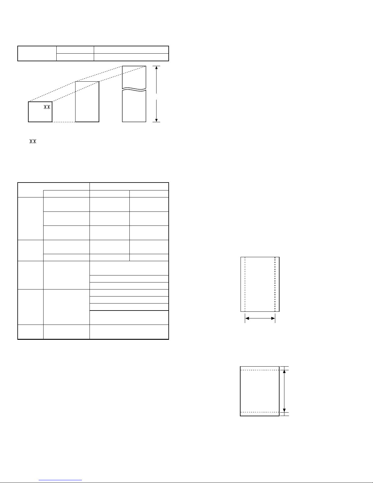
7. Use of Document Carrier Sheet
A document carrier sheet must be used for the following documents.
•Those with tears.
•Those smaller than size 5.83" (W) ×5.04" (L) (148 mm (W) ×128
mm (L)).
•Carbon-backed documents
NOTE: To transmit a carbon-backed document, insert a white sheet of
paper between the carbon back of the document and the docu-
ment carrier.
•Those containing an easily separable writing substance (e.g., trac-
ing paper written on with a soft, heavy lead pencil).
NOTES: •When using the document carrier, carefully read the in-
structions written on the back.
•If the document carrier is dirty, clean it with a soft, moist
cloth, and then dry it before using for transmission.
•Do not place more than one document in the carrier at a
time.
•The thickness of document which can be held with the carrier sheet
is up to 20 lb.
[4] Installation
1. Site selection
Take the following points into consideration when selecting a site for this
model.
ENVIRONMENT
•The machine must be installed on a level surface.
•Keep the machine away from air conditioners, heaters, direct sun-
light, and dust.
•Provide easy access to the front, back, and sides of the machine. In
particular, keep the area in front of the machine clear, or the original
document may jam as it comes out after scanning.
•The temperature should be between 41°and 95°F (10°and 35°C).
•The humidity should be between 30% and 85% (without condensa-
tion).
ELECTRICITY
A 120 V, 60 Hz, grounded (3-prong) AC outlet is required.
Caution!
•Connection to a power source other than that specified will cause
damage to the equipment and is not covered under the warranty.
•Ifyour area experiencesa high incidenceof lightning orpower surges,
we recommend that you install a surge protector for the power and
telephonelines.Surge protectors canbepurchased at most telephone
specialty stores
TELEPHONE JACK
A standard RJ11C telephone jack must be located near the machine.
This is the telephone jack commonly used in most homes and offices.
•Plugging the fax machine into a jack which is not an RJ11C jack may
result in damage to the machine or your telephone system. If you do
not know what kind of jack you have, or need to have one installed,
contact the telephone company.
If the machine is moved from a cold to a warm place...
If the machine is moved from a cold to a warm place, it is possible that
the reading glass may fog up, preventing proper scanning of documents
for transmission. To remove the fog, turn on the power and wait approxi-
mately 2 hours before using the machine.
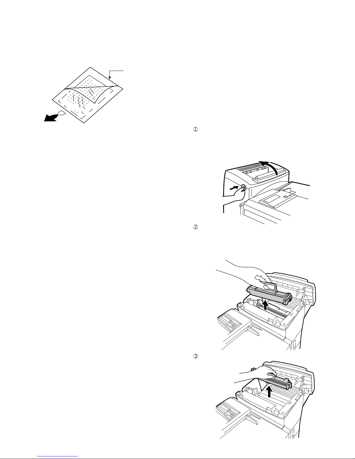
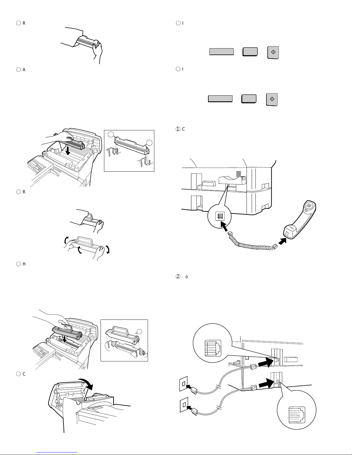
2. Installing the printer cartridges (Toner
cartridge: FO-45ND/Drum cartridge: FO-45DR)
1
Press the button on the side of the printer compartment, and open
the printer cover.
•Caution! The ribs on the bottom of the inside of the printer cover
become very hot during printing. Be careful not to touch them.
•If you are installing the cartridges for the first time, go to Step 4.
3
Pull the old drum cartridge out of the compartment.
2
If you are replacing the cartridges, grasp the handle on the toner
cartridge, and pull the toner cartridge out of the compartment.
•If you are only replacing the drum cartridge, place the toner car-
tridge on a piece of paper on a horizontal surface.
•If you are only replacing the toner cartridge, go to Step 6.
Direction of insertion
Make print straight
across paper
E.G.
Place the document
carrier in the document
feeder with the clear film
side down

1 – 6
FO-6600U
3. Assembly and connections
1
Connect the handset cord to the handset and the fax as shown.
•The ends of the handset cord are identical, so they will go into
either jack.
Place the handset on the handset rest.
4
Remove the new drum cartridge from its packaging.
5
Align the arrowhead on the right side of the drum cartridge (the right
side is marked "R") with the arrowhead pointing down on the right
side of the compartment, and insert the cartridge into the compart-
ment so that the ends of the cartridge move along the guides on the
sides of the compartment. Make sure the cartridge is set firmly in
place.
•Place the old drum cartridge (if you removed one) in the empty
drum cartridge bag, seal the bag, and dispose of it in a way that
conforms to any local regulations that may exist in your area.
•If you are not replacing the toner cartridge, go to Step 7.
6
Remove the new toner cartridge from its packaging, and shake it
several times as shown.
•This ensures that the toner is well distributed inside the cartridge.
8
Close the printer cover.
9
If you replace the toner cartridge, reset the toner counter by pressing
the LIFE key (flip up the Rapid Key overlay if necessary), the "2" key,
and the START key.
7
Hold the handle of the toner cartridge so that the "2" marked on the
cartridgeis tothe right, and insert the cartridge into the com-partment
that the two knobs on each side of the cartridge move along the two
guides on each side of the compartment. Press the handle down so
that the cartridge sets into place.
•Place the old toner cartridge (if you removed one) in the empty
toner cartridge bag, seal the bag, and dispose of it in a way that
conforms to any local regulations that may exist in your area.
2
Connect the LINE 1 jack and the LINE 2 jack to the appropriate wall
jacks with the telephone line cords. The wall jacks should be stand-
ard (RJ11C) single-line wall jacks for separate lines.
•Note: Voicecommunications,manual fax transmission andmanual
fax reception are only possible on Line 1.
•The fax machine will only ring when a call is received on Line 1 (it
will not ring when a call is received on Line 2).
Use the handset to make ordinary
phone calls, or to transmit and
receive documents manually.
Left
L
R1
Right
2
Left
Right
LIFE
V
2
START
LIFE
V
3
START
TEL.
LINE
TEL.
LINE
LINE 1
LINE 2
F
If you replace the drum cartridge, reset the drum counter by pressing
the LIFE key (flip up the Rapid Key overlay if necessary), the "3" key,
and the START key.

1 – 7
FO-6600U
3
Plug the power cord into a 120V, 60Hz, grounded (3-prong) AC
outlet.
Press the power switch to turn on the power.
6
Insert the male end of the PC interface cable into the port on the right
sideof fax as shown.Tightenthe attached screws with a screwdriver.
4
Attach the original document OUT tray by inserting the tabs into the
holes in the fax as shown.
5
Attachthe received document tray by inserting thetabs into the holes
in the fax as shown.
7
Insertthefemale end ofthePC interface cable intothe serial (RS232C)
port on your computer. Tighten the attached screws with a screw-
driver.
4. Loading printing paper
The paper cassettes and the paper tray hold the paper on which re-
ceived documents are printed. The FO-6600 comes with two paper cas-
settes. Each paper cassette can hold 500 sheets of either legal or letter
size paper. The paper tray can hold 150 sheets of either legal or letter
size paper.
1
Grasp the handhold on thecassette as shown,lift the cassetteslightly,
and then pull it out as far as it will go. Do not force. Push down on
green levers on both sides of the cassette tray as shown, and then
pull it completely out of the fax using both hands.
OFF 0
ON |

1 – 8
FO-6600U
2
Pinch the ends of the paper guide together, and move the guide to
the appropriate position depending on whether you are loading letter
or legal size paper.
6
If desired, attach a letter or legal sticker as appropriate to the cas-
sette.
7
Rotate the received document tray back. Grasp the hand hold on the
original document IN tray as shown, and open it.
3
Push the pressure plate down until it locks into position.
4
Place a stack of paper in the cassette, print side up. Make sure the
two far corners of the paper go under the paper holders as shown.
•Make sure the stack of paper is not higher than the tabs at the top
of the paper guide. If it is, remove some of the paper.
5
Put the cassette back in the fax.
8
Move the paper guide to the appropriate position depending on
whether you are loading letter or legal paper.
•Toremove the paper guide, press its inner side atthe arrowmarks
and lift.
9
Place the paper in the tray.
F
Close the original document IN tray.
G
If desired, attach a letter or legal sticker as appropriate to the fax as
shown.
LGL
LTR
Letter Legal

1 – 9
FO-6600U
5. Clearing paper jams
If a document doesn’t feed through the scanner properly during trans-
mission or copying, or DOCUMENT JAM appears in the display, first try
pressingtheSTART key.If thedocument doesn’tcome outof thefeeder,
open the operation panel by squeezing the operation panel release on
the right side of the operation panel (marked "PULL OPEN"), and gently
pull out document.
1
5
Replace the drum cartridge, and then the toner cartridge.
2
If the leading edge of the document is protruding from the printer
compartment outlet, try pulling it out.
•If you are unable to clear the paper jam in this way, continue with
the following steps.
3
Open the printer cover and remove the toner cartridge and drum
cartridge.
•Caution! The ribs on the bottom of the inside of the printer cover
become very hot during printing. Be careful not to touch them.
4
Gently pull the paper out of the compartment.
•If the leading edge of the paper has entered the fusing unit, first
pull the leading edge out of the fusing unit, then pull the paper out
of the compartment.
•Be sure to remove any torn pieced of paper.
6
Close the printer cover.
7
If you didn’t find any paper in the printer compartment, or if PAPER
JAMstill appears in the displayafter youclose the printer cover,check
each paper cassette and the paper tray.
•To release the cassette when pulling it out, press down on the
levers on each side of the cassette.
•To check the paper tray, grasp the hand hold on the original docu-
ment IN tray and rotate the tray up.
8
Gently pull out any jammed paper you find, and then replace the
cassette or close the original document IN tray.
Left
L
R1
Right
2
Left
Right

1 – 10
FO-6600U
[5] Quick reference guide
FUNCTION key menu
The following chart shows the layout of the functions and settings accessed by pressing the FUNCTION key. First press the FUNCTION key, the
appropriate numeric key as shown, and then "#" or " " until the desired item appears. Instructions for making each setting appear in the display. Refer
to the detailed instructions on the page shown below the setting.
Note: Steps which are optional are enclosed in a dotted frame:
Print Hold
Mode
Hold Data Print
Print Hold Code
Set
Print Hold Code
Clear
Listing Mode
Activity Report
Timer List
Telephone
Number List
Relay Group List
Passcode List
Option Setting
List
Program/Group
List
Batch
Transmission List
Department
Usage List
Confidential
Reception List
Anti Junk Fax
Number List
Entry Mode
Fax/Tel
Numbers for
Auto Dialing
Passcode Number
Own Number and
Name Set
Date and Time
Set
Day Light Saving
ID Number
System Number
Store Junk Fax
Number
Department
Code Mode
Optional Settings
Fine Resolution
Priority
Number of Rings in
Auto Answer Mode
Number of Rings to
Auto Manual Answer
Auto Listing
Transaction Report
Print Select
Recall Times
Recall Wait Interval
Security Selection
ECM
Auto cover Sheet
Memory Scanning
Copy Reduce
Copy Cut-off
Receive Reduce
Image Memory
Print
Cassette Selection
Cassette
Changeover
Program/Group
Mode
Program Entry
Mode
Group Entry
Mode
Serial Polling
Mode Memory Polling
Mode
Memory Polling Set
Memory Polling
Clear
Reception
Mode Retransmission
Times
Retransmission
Interval
Heater Mode
Junk Fax Check
Alarm Buzzer
Dial Mode
Quick on Line
Multi TTI
Beep Length
Tel. Billing Code
Department Code
Mode
Distinctive Ringing
Verification Stamp
Print Hold
PC-Interface Mode
Receive Unit
Dial Selection
Separate Mode
12346789
FUNCTION
RESOLUTION LINE
Load
document
Lift handset
or
press SPEAKER
Dial (press
numeric keys)
Wait for
reception tone Hang up
Load
document
Load
document
Load
document
Dial (press
numeric keys)
Press Rapid
key
Enter Speed Dial number
(press numeric keys, -if less
than 3 digits, press START
to complete entry)
Normal Dialing (1)
Direct Keypad
Dialing
Rapid Key Dialing
Speed Dialing
Transmitting documents
RESOLUTION
RESOLUTION
START
Load
document
Lift handset
or
press SPEAKER
Dial (press
numeric keys)
Wait for
reception tone Hang up
Normal Dialing (2)
RESOLUTION
START
RESOLUTION
RESOLUTION
START
SPEED DIAL
START
LINE
LINE
Load
document Wait for
reception tone
Redialing
RESOLUTION
REDIAL
START
LINE
Table of contents
Other Sharp Fax Machine manuals

Sharp
Sharp UX-53 User manual

Sharp
Sharp UX-P110 User manual

Sharp
Sharp A260 - UX B/W Thermal Transfer User manual

Sharp
Sharp FO-1460 User manual

Sharp
Sharp UX-P410 User manual

Sharp
Sharp FO-A660 User manual

Sharp
Sharp FO-50 User manual

Sharp
Sharp UX-B800SE - B/W Inkjet - Fax User manual

Sharp
Sharp UX-B30 User manual

Sharp
Sharp UX-465L User manual