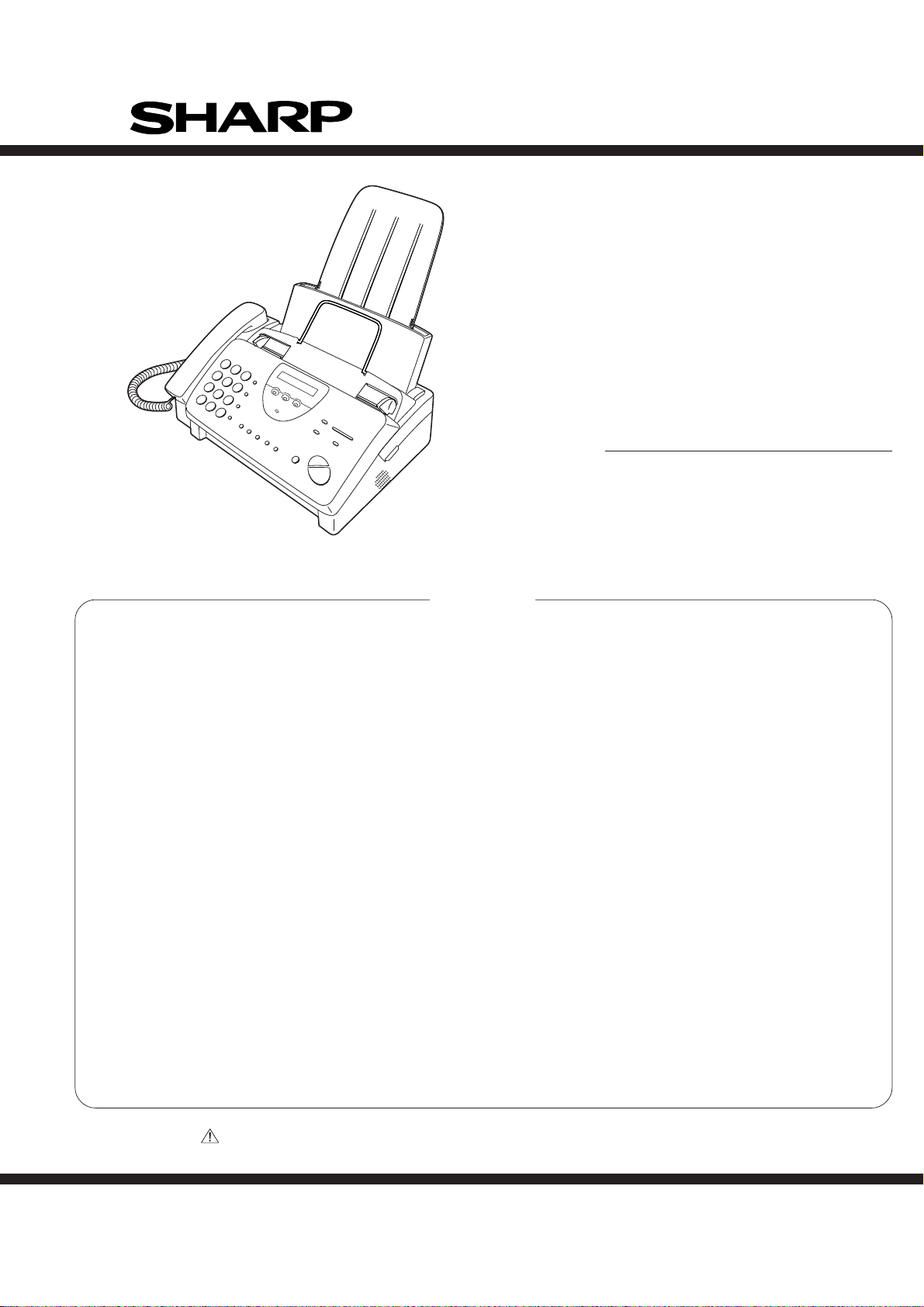
Sharp UX-460 User manual

1 - 1
UX-460U
This service manual UX-460U is to appear only on the place where it is changed from UX-300U/FO-760U, and refer to a
service manual UX-300U/FO-760U (00ZUX300U/SME) except for it.
No. 00ZUX460U/SME
CHAPTER 1. GENERAL DESCRIPTION
[1] Specifications ............................................ 1-1
[2] Operation panel......................................... 1-2
[3] Refer to the service manual of UX-300U.
[4] Refer to the service manual of UX-300U.
[5] Refer to the service manual of UX-300U.
[6] Refer to the service manual of UX-300U.
CHAPTER 2. ADJUSTMENTS
[1] Adjustments............................................... 2-1
[2] Diagnostics and service soft switch .......... 2-2
[3] Troubleshooting...................................... 2-18
[4] Error code table....................................... 2-19
CHAPTER 3. MECHANISM BLOCKS
[1] Refer to the service manual of UX-300U.
[2] Refer to the service manual of UX-300U.
CHAPTER 4. DIAGRAMS
[1] Block diagram ............................................4-1
[2] Wiring diagram .......................................... 4-2
[3] Point-to-point diagram............................... 4-3
CHAPTER 5. CIRCUIT DESCRIPTION
[1] Circuit description...................................... 5-1
[2] Circuit description of control PWB..............5-2
[3] Circuit description of TEL/LIU PWB .......... 5-8
[4] Circuit description of
power supply PWB............................5-11
[5] Circuit description of CIS unit...................5-11
CHAPTER 6. CIRCUIT SCHEMATICS AND
PARTS LAYOUT
[1] Control PWB circuit ................................... 6-1
[2] TEL/LIU PWB circuit ................................. 6-9
[3] Power supply PWB circuit ....................... 6-11
[4] Operation panel PWB circuit ................... 6-13
CHAPTER 7. OPERATION FLOWCHART
[1] Refer to the service manual of UX-300U.
[2] Refer to the service manual of UX-300U.
CHAPTER 8. OTHERS
[1] Refer to the service manual of UX-300U.
[2] Refer to the service manual of UX-300U.
[3] Changing the record paper size ............... 8-9
PARTS GUIDE
CONTENTS
FACSIMILE
UX-300
MODEL UX-460
Parts marked with " " is important for maintaining the safety of the set. Be sure to replace these parts with specified ones for
maintaining the safety and performance of the set.
This document has been published to be used
for after sales service only.
The contents are subject to change without notice.
SHARP CORPORATION
SERVICE MANUAL

1 –2
UX-460U
(Danish) ADVARSEL!
Lithiumbatteri-Eksplosionsfare ved fejlagtig håndtering.
Udskiftning må kun ske med batteri af samme fabrikat og type.
Levér det brugte batteri tilbage til leverandoren.
(English) Caution !
Danger of explosion if battery is incorrectly replaced.
Replace only with the same or equivalent type
recommended by the equipment manufacturer.
Discard used batteries according to manufacturer’s
instructions.
(Finnish) VAROITUS
Paristo voi räjähtää, jos se on virheellisesti asennettu.
Vaihda paristo ainoastaan laitevalmistajan suosittelemaan
tyyppiin. Hävitä käytetty paristo valmistajan ohjeiden
mukaisesti.
(French) ATTENTION
Il y a danger d’explosion s’ il y a remplacement incorrect
de la batterie. Remplacer uniquement avec une batterie du
même type ou d’un type recommandé par le constructeur.
Mettre au rébut les batteries usagées conformément aux
instructions du fabricant.
(Swedish) VARNING
Explosionsfare vid felaktigt batteribyte.
Använd samma batterityp eller en ekvivalent
typ som rekommenderas av apparattillverkaren.
Kassera använt batteri enligt fabrikantens
instruktion.
(German) Achtung
Explosionsgefahr bei Verwendung inkorrekter Batterien.
Als Ersatzbatterien dürfen nur Batterien vom gleichen Typ oder
vom Hersteller empfohlene Batterien verwendet werden.
Entsorgung der gebrauchten Batterien nur nach den vom
Hersteller angegebenen Anweisungen.
CAUTION FOR BATTERY REPLACEMENT

1 – 1
UX-460U
CHAPTER 1. GENERAL DESCRIPTION
[1] Specifications
Automatic dialing: Rapid Key Dialing: 5 numbers
Speed Dialing: 40 numbers
Imaging film: Initial starter roll (included with fax
machine): 32 ft. (10 m) roll (approx. 30
letter-size pages)
Replacement roll:
UX-3CR 98 ft. (30 m) roll (two rolls in
package, one roll yields approx. 100
letter-size pages)
Automatic document feeder: 10 sheets max.
Memory size* : 512 KB (approx. 30 average pages with
no voice messages recorded, or 24
minutes of voice messages (including
OGMs) with no documents in memory)
Modem speed: 9600 bps with automatic fallback to
7200, 4800, or 2400 bps
Transmission time* : Approx. 15 seconds (Sharp special mode)
Reception modes: TEL/FAX/TAD
Resolution: Horizontal:
203 pels/inch (8 dots/mm)
Vertical:
Standard: 98 lines/inch
(3.85 lines/mm)
Fine/Halftone: 196 lines/inch
(7.7 lines/mm)
Super fine: 391 lines/inch
(15.4 lines/mm)
Display: 16-digit LCD display
Recording system: Thermal transfer recording
Paper tray capacity: Letter: 60 sheets
(16- to 20-Ib. paper) Legal: 30 sheets
Halftone (grayscale): 64 levels
Applicable telephone line: Public switched telephone network
Compatibility: ITU-T (CCITT) G3 mode
Compression scheme: MH, MR, Sharp
Scanning method: Sheet-feeder CIS (Contact Image Sensor)
Effective recording width: 8.3" (210 mm) max.
Input document size: Automatic feeding:
Width 5.8 to 8.5"
(148 to 216 mm)
Length 5.5 to 11"
(140 to 279 mm)
Manual feeding:
Width 5.8 to 8.5"
(148 to 216 mm)
Length 5.5 to 23.6"
(140 to 600 mm)
Effective scanning width: 8.3" (210 mm) max.
Contrast control: Automatic/Dark selectable
Copy function: Single/Multi-copy/Sort-copy (99 copies
/page)
Telephone function: Standard
(cannot be used if power fails)
Power requirements: 120 V AC, 60 Hz
Operating temperature: 41 to 95°F (5 to 35°C)
Humidity: Maximum: 85 %
Power consumption: Stand-by: 4.5 W
Maximum: 100 W
Dimensions: Width: 13.5" (343 mm)
Depth: 10.1" (256 mm)
Height: 7.2" (182 mm)
Weight: Approx. 7.3 lbs. (3.3 kg)
* BasedonITU-T(CCITT)Test Chart #1 at standard resolution in Sharp
special mode, excluding time for protocol signals (i.e., ITU-T phase C
time only).
Note: The facsimile machine is Year 2000 compliant.
As a part of our policy of continuous improvement, SHARP reserves the right to make design and specification changes for procduct
improvement without prior notice. The performance specifications figures indicated are nominal values of production units. There may be some
deviation from these values in individual units.

1 – 2
UX-460U
[2] Operation panel
13 15 1718
12
10
11
1 6 7 8
2 3
19
9
1. SPEED DIAL key
Press this key to dial a 2-digit Speed Dial number.
2. REDIAL key
Press this key to automatically redial the last number dialed.
3. REPEAT key
Press this key to repeat playback of a message.
4. Display
This displays messages and prompts during operation and
programming.
5. PLAY/SKIP key
Press this key to play recorded messages. During playback,
press it to skip forward to the next message.
6. RECEPTION MODE key
Press this key to select the reception mode. An arrow in the
display will point to the currently selected reception mode.
7. RESOLUTION key
Press this key to adjust the resolution and contrast before
sending or copying a document.
8. VOLUME keys
Press these keys to adjust the volume of the handset when
the handset is lifted, the volume of the speaker when the
SPEAKER key has been pressed, or the volume of the ringer
at all other times.
9. FUNCTION key
Press this key to select various special function.
10. Panel release
Grasp this finger hold and pull toward you to open the operation
panel.
11. Number keys
Use these keys to dial numbers, and enter numbers and
letters during number/name storing procedures.
12. HOLD/SEARCH key
Press this key to search for an automatic dialing number,
or, during a phone conversation, press this key to put the
other party on hold.
13. SPEAKER key
Press this key to hear the line and fax tones through the
speaker when sending a document.
Note: This is not a speakerphone. You must pick up the
handset to talk with the other party.
14. REC/MEMO key
Press this key to record a phone conversation or a
message.
15. Rapid Dial keys
Press one of these keys to dial a fax or voice number
automatically. (Note that you must attach the Rapid Key
labels.)
16. DELETE key
Press this key to erase recorded message.
17. STOP key
Press this key to cancel operations before they are
completed.
18. START/MEMORY key
Press this key to send or receive a document, or to scan a
document into memory before sending it.
19. COPY/HELP key
When a document is in the feeder, press this key to make
a copy. At any other time, press this key to print out the
Help List, a quick reference guide to the opeation of your
fax.
JKL
SPEED
DIAL
REDIAL
SPEAKER
HOLD/
SEARCH
REPEAT REC/MEMO PLAY/SKIP
DELETE
STOP
COPY/HELP
START/MEMORY
VOLUME
DOWN UP
RECEPTION
MODE
RESOLUTION FUNCTION
TEL FAX
TAD
ABC 2
1DEF 3
WXYZ
9
GHI 45MNO6
PQRS
7TUV 8
005/POLL04030201
DIGITAL ANSWERING
SYSTEM
45
14 16

UX-460U
CHAPTER 2. ADJUSTMENTS
[1] Adjustments
General
Sincethefollowingadjustmentsandsettingsareprovidedforthismodel,
make adjustments and/or setup as necessary.
1. Adjustments
Adjustments of output voltage (FACTORY ONLY)
1. Install the power supply unit in the machine.
2. Set the recording paper and document.
3. When the document is loaded, power is supplied to the output lines.
Confirm that outputs are within the limits below.
Output voltage settings
(1)FU100 (ICP-S07) is installed in order to protect IC’s from an over-
current generated in the motor drive circuit. If FU100 is open, replace
it with a new one.
3. Settings
(1) Dial mode selector
DIAL mode (Soft Switch No. SWB4 DATA No. 3)
Output Voltage limits
+5V 4.75V ∼ 5.25V
+24V 23.3V ∼ 24.7V
2. IC protectors replacement
ICPs (IC Protectors) are installed to protect the motor driver circuit.
ICPsprotectvariousICsandelectroniccircuitsfromanovercurrentcon-
dition.
The location of ICPs are shown below:
1MG
2MG
3 +24V
4 +24V
5 +24V
6DG
7 +5V
8DG
Connector
No. CNPW
Pin No.
2 – 1
TEL/LIU PWB
POWER
SUPPLY
PWB
CONTROL
PWB
CNLIUA
CNLIU CN2
CNPW
CNTH
CNPN
CNCIS
CNSP
CNMT
CNCSW
CONTROL PWB
(BOTTOM SIDE)
CNPW CNLIUA
FU100
(step 1) Select "OPTION SETTING".
KEY : FUNCTION 4
DISPLAY: OPTION SETTING PRESS OR #
(step 2) Select "DIAL MODE".
KEY: Push # until " DAIL MODE " is
indicated because the number of
# s changes by the model.
DISPLAY: DIAL MODE
(step 3) Select, using "1" or "2".
KEY: 1
DISPLAY: TONE SELECTED
KEY: 2
DISPLAY: PULSE SELECTED
(step 4) End, using the "STOP" key.
KEY:
Cursor
When initially registering,
the mode shows 1=TONE.
When registering again, the
mode which was registered
formerly is shown.
STOP
1=TONE, 2=PULSE

UX-460U
[2] Diagnostics and service soft switch
1. Operating procedure
(1) Entering the diagnostic mode
Press FUNC →9 →→ 8 →# →7 , and the following display will appear.
ROM Ver. FKQ0 After 2 sec: DIAG MODE
FKQ0
Then press the START key. Select the desired item with the key or the # key or select with the rapid key. Enter the mode with the START key.
(Diag•specifications)
2. Diagnostic items
ITEM DIRECT Contents Function
No. key
1 1 SOFT SWITCH MODE Soft switches are displayed and changed. List can be output.
2 2 ROM & RAM CHECK ROM is sum-checked, and RAM is matched. Result list is output.
3 3 AGING MODE 10 sheets of check patterns are output every 5 minutes per sheet.
4 4 PANEL KEY TEST Panel keys are tested. Result list is output.
5 5 CHECKPATTERN Check pattern is output.
6 — SIGNAL SEND MODE Various signals of FAX communication are output.
7 — MEMORY CLEAR Back-up memory is cleared, and is set at delivery.
8 — SHADING MODE Shading compensation is performed in this mode.
9 — ALL BLACK PRINT To check the print head, whole dots are printed over the interval of 2 m.
10 — AUTO FEEDER MODE Insertion and discharge of document are tested.
11 — ENTRY DATA SEND Registered content is sent.
12 — ENTRY DATA RECEIVE Registered content is received, and its list is output.
13 — Flash memory check Checks flash memory write/read.
14 — Flash memory clear Checks flash memory clearing.
If the diag mode cannot be set, repeat the diag mode operation, per-
forming the following operation.
After the power is turned on and "WAITAMOMENT" is indicated, press
the STOP key.
2 – 2
In relation with the process response (request from Production
Engineering)"WAITAMOMENT"clockindicationmay appear depending
onSTOPkeytiming.IftheSTOPkey is held down, "MEMORYCLEAR?"
appears.
FUNC DIAG MODE
9 8 7
START 1Soft switch mode
START 2ROM & RAM check
START 3Aging mode
START 4Panel key test
START 5Check pattern
STARTSignal send mode
Auto feeder mode
START
START
Entry data send
START Entry data receive
START
Flash memory check
Flash memory clear
START
START
START
KEY
STOP
KEY +
+
"Power ON"
Memory clear
(Work + Backup)
FKQ0
All black mode
START
STARTMemory clear Shading mode
START

UX-460U
3. Diagnostic items description
3. 1. Soft switch mode
Used to change the soft switch settings.
The soft switch which is stored internally is set by using the keys.
The available soft switches are SW-A1 to SW-M2.
The content of soft switches is shown in page 2-5 to 2-17.
The contents are set to factory default settings.
3. 2. ROM & RAM check
ROM executes the sum check, and RAM executes the matching test.
The result will be notified with the number of short sounds of the buzzer
as well as by printing the ROM & RAM check list.
Number of short sounds of buzzer 0 →No error
1 → ROM error
2 → RAM error (32Kbyte)
3. 3. Aging mode
Ifanydocumentisfirstpresent,copyingwillbeexecutedsheetbysheet.
If no document is present, the check pattern will be printed sheet by
sheet. This operation will be executed at a rate of one sheet per 5min-
utes, and will be ended at a total of 10 sheets.
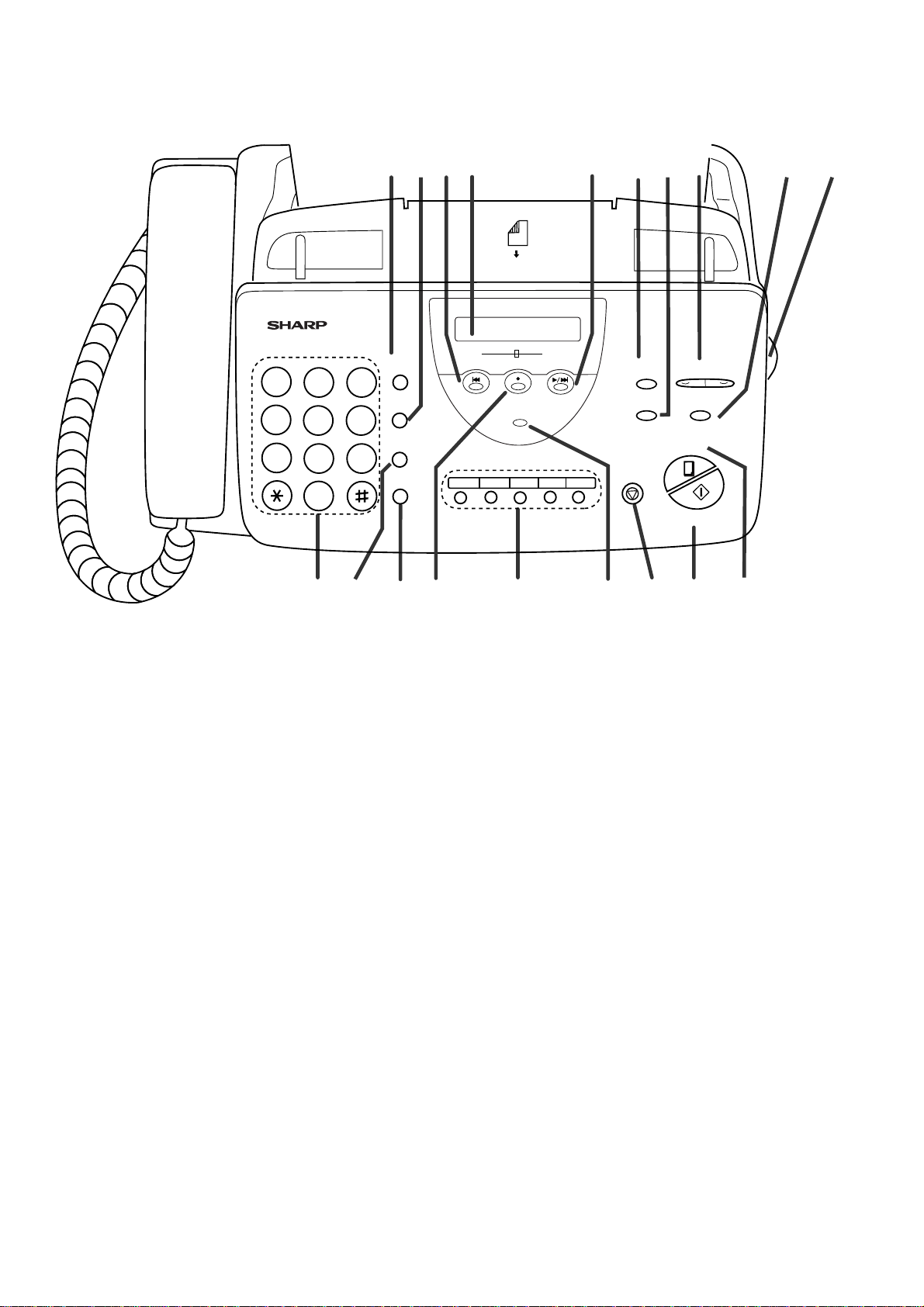
3. 4. Panel key test
This mode is used to check whether each key operates properly or not.
Press the key on the operation panel, and the key will be displayed on
thedisplay.Therefore,pressallkeys.At this time,finally press the STOP
key.
When the STOP key is pressed, the keys which are not judged as
"pressed" will be printed on the result list.
• LED port of the contact image sensor (CIS) is kept on during the term
from when start of the panel test mode to end with the STOP key.
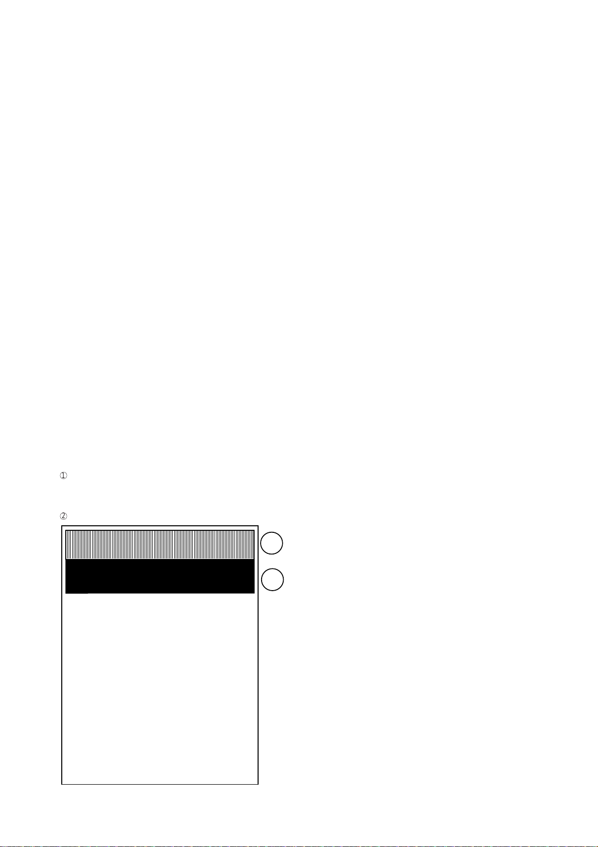
3. 5. Check pattern
This mode is used to check the state of the printing head. It is ended
with the following pattern printed on one printing sheet.
1
Longitudinal stripe 2 Approx. 30 mm
2 black dots and 2 white dots are repeatedly progressed on one
line.
2
Full black Approx. 30 mm
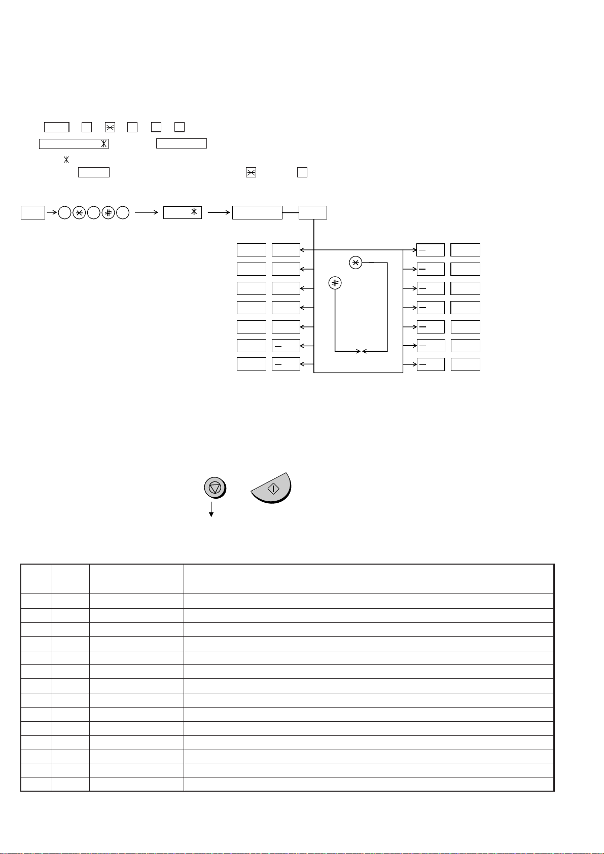
3. 6. Signal send mode
This mode is used to send various signals to the circuit during FAX com-
munication. Every push of START key sends a signal in the following
sequence.Moreover, thesignalsoundisalsooutputto the speaker when
the line monitor of the soft switch is on.
[1] No signal (CML signal turned on)
[2] 9600bps
[3] 7200bps
[4] 4800bps
[5] 2400bps
[6] 300bps (FLAG)
[7] 2100Hz (CED)
[8] 1100Hz (CNG)
[9] GENERALOGM PLAY(Only when GENERALOGMisrecorded.)
[10] END
3. 7. Memory clear
This mode is used to clear the backup memory and reset to the default
settings.
3. 8. CCD adjust mode
This mode is used to adjust the optical system. Since the copy function
is performed, set the original. To abort the copy operation, press the
STOPkey. To restart press the START key. When the copy is completed
or when the STOP key is pressed in the interruption state, exit from this
mode occurs.
3. 9. All black print
This mode is used to check the state of the printing head and inten-
tionally overheat it. Whole dots are printed over the interval of 2 m. If it is
overheatedortheprintingsheetisjammed,pressSTOPkeyforthe end.
3. 10. Auto feeder mode
In this mode, a document is inserted and discharged to check the auto
feed function.
After this mode is started, set a document, and the document feed will
be automatically tested.
3. 11. Entry data send
This mode is used to send the registered data to the other machine and
make the other machine copy the registered content.
Before sending in this mode, it is necessary to set the other machine at
the entry data receive mode.
The following, information will be sent to the remote machine:
1. Telephone list data
2. Sender register data
3. Optional setting content
4. Soft switch content
5. Junk fax number list
6. Timer reservation data (only on the model which timer reserva-
tion is possible)
7. Recording setting list data
2 – 3
1
2

UX-460U
3. 12. Entry data receive
In this mode, the registered data sent from the other machine is receiv-
ed and the received data is registered in the machine. When this mode
is used for receiving, the other machine must be in the entry data send
mode.
After receiving is completed, the following lists are printed.
1. Telephone list data
2. Senderregisterdata(The passcodeNo.isalso printed ifthepolling
function is provided.)
3. Optional setting list
4. Soft switch content
5. Junk fax number list
6. Timer reservation list (only model which timer communication is
possible)
7. Recording setting list data
2 – 4
Press FUNCTION 9 8 7 STARTSTART
Press FUNCTION key.
Press key.
Press key.
Bit1 - 8 are set.
Soft SW-A2 - SW-M2 are set.
S F T SW-A1 = 1 0 0 0 0 0 0 0
S F T SW-A2 = 0 0 0 0 0 0 0 0
S F T SW-M2 = 0 0 0 0 0 0 0 0
Press key during setting.
To finish the settings halfway between
SW-A1 and SW-M2, press the STOP
key. In this case, the setting being done
to the SW No. on display will be nullified
while settings done to the preceding
SW Nos. remain in effect.
The soft switch mode is terminated.
S F T SW-A1 = 0 0 0 0 0 0 0 0
START
DATA No. 1 2 3 4 5 6 7 8
When the COPY key is pressed, the
contents of soft switches are printed.
3. 13. Flash memory check
Data is written into and read from the flash memory to check the data
conformity. When the unit enters this mode, the check is started.
3. 14. Flash memory clear
Dataintheflashmemory is cleared (memoryclear).Whentheunitenters
this mode, the check is started.
*Operation of hardware and signal in the flash memory check mode and
flash memory clear mode, and the result of check
The result is announced by the buzzer beeps. The result of check is
printed.
Beeps
0 → No error
1 → Memory error
4. How to make soft switch setting
To enter the soft switch mode, make the following key entries in se-
quence.

UX-460U
1 Protect from echo No Yes 0
2 Forced 4800 BPS reception Yes No 0
3 Footer print Yes No 0
4 Length limitation of copy/send/receive No limit Copy/send: 1m 0
Receive: 1.5m
5 CSI transmission No transmitted Transmitted 0
6 DIS receive acknowledgement during G3 Twice NSF: Once 0
transmission DIS: Twice
7 Non-modulated carrier for V29 transmission Yes No 0
modem
8 EOL detect timer 25 s 13 s 0
Modem speed V.29 V.27 ter
9600bps 7200bps 4800bps 2400bps
1 No. 1 0 0 0 0 0
2 No. 2 0 0 0 0 0
3 No. 3 0 1 1 0 0
4 No.4 1 1 0 0 1
5 Sender’s information transmit No Yes 0
6 H2 mode No Yes 0
7 Communication error treatment in RTN No communication error Communication error 0
sending mode (reception)
8 CNG transmission No Yes 0
CED tone signal interval 1000ms 750ms 500ms 75ms
1 No. 1 1 1 0 0 0
2 No. 2 1 0 1 0 0
3 MR coding No Yes 0
4 Reserved 0
5 Reserved 0
6 Reserved 0
7 Reserved 0
8 Reserved 0
1 Signal transmission level Binary input 0
2 No. = 16 8 4 2 1 1
3 1 2 3 4 5 0
4 0 1 0 0 0 0
5 0
6 Protocol monitor (error print) Printed at com. err Not printed 0
7 Protocol monitor Yes No 0
8 Line monitor Yes No 0
Digital line equalization setting (Reception) 7.2km 0km
1 No. 1 1 0 1
2 No. 2 1 0 1
3 Reserved 0
4 Reserved 0
Digital cable equalizer setting (Reception 7.2km 0km
5 for Caller ID) No. 5 1 0 0
6 No. 6 1 0 0
7 Error criterion 10 ~ 20 % 5 ~ 10 % 0
8 Anti junk fax check Yes No 0 OPTION
5. Soft switch description
• Soft switch
SW
NO. DATA
NO. ITEM Switch setting and function
10
Remarks
Initial
setting
SW
l
A1
SW
l
A2
SW
l
A3
SW
l
A5
SW
l
A4
2 – 5

UX-460U
1 Auto gain control (MODEM) Enable Disable 1
2 End Buzzer Yes No 1
3 Disconnect the line when DIS is received in No Yes 1
RX mode
4 Equalizer freeze control (MODEM) On Off 0
5 Equalizer freeze control 7200 BPS only No Yes 0
6 CNG transmission in manual TX mode Yes No 1
7 Initial compression scheme for sharp fax in MR mode H2 mode 0
TX mode
8 Reserved 0
1 Recall interval Binary input 0 OPTION
2 No. = 8 4 2 1 1
3 1 2 3 4 0
4 0 1 0 1 1
5 Recall times Binary input 0 OPTION
6 No. = 8 4 2 1 0
7 5 6 7 8 1
8 0 0 1 0 0
1 Dial pausing (sec/pause) 4 sec 2 sec 0
2 Reserved 0
3 Reserved 0
4 Busy tone detection (after auto dial) No Yes 0
5 Waiting time after dialing 90 sec 45 sec 0
6 Reserved 0
7 Reserved 0
8 Reserved 0
1 Reserved 0
2 Reserved 0
3 Reserved 0
4 Reserved 0
5 Reserved 0
6 Reserved 0
7 Reserved 0
8 Reserved 0
1 Auto Dial Mode Delay timer of before line 3 sec 0 sec 0
connect
2 Auto Dial Mode Delay timer of after line 3 sec 1.7 sec 0
connect
3 Dial mode Tone Pulse 1 OPTION
4 Pulse →Tone change function by key Enable Disable 0
5 Reserved 0
6 Reserved 0
7 Reserved 0
8 Reserved 0
1 DTMF signal transmission level (Low) Binary input 0
2 No. = 16 8 4 2 1 1
3 1 2 3 4 5 0
4 0 1 0 1 1 1
5 1
6 Reserved 0
7 Reserved 0
8 Reserved 0
SW
NO. DATA
NO. ITEM Switch setting and function
10Remarks
Initial
setting
SW
l
B5
SW
l
B4
SW
l
B3
SW
l
B2
SW
l
B1
SW
l
A6
2 – 6

UX-460U
1 DTMF signal transmission level (High) Binary input 0
2 No. = 16 8 4 2 1 0
3 1 2 3 4 5 1
4 0 0 1 1 0 1
5 0
6 Reserved 0
7 Reserved 0
8 Reserved 0
Reading slice (Binary) Factory Light Dark Darker in
setting dark mode
1 No. 1 0 1 0 1 0
2 No. 2 0 0 1 1 0
Reading slice (Half tone) Factory Light Dark Darker in
setting dark mode
3 No. 3 0 1 0 1 0
4 No. 4 0 0 1 1 0
5 Line density selection Fine Standard 0 OPTION
6 Reserved 0
7 MTF correction in half tone mode No Yes 0
8 Reserved 0
1 Number of rings for auto receive Binary input 0 OPTION
2 No. = 8 4 2 1 1
3 1 2 3 4 0
4 0 1 0 0 0
5 Automatic switching manual to auto receive Reception after 5 rings No reception 0
mode
6 Reserved 0
7 Reserved 0
8 Reserved 0
Distinctive ringing setting No.1 No.2 No.3 OPTION
Factory setting: OFF OFF 0 0 0
(PATTERN 4 and 5 are for CANADA only) STANDARD 0 0 1
PATTERN1 0 1 0
PATTERN2 0 1 1
1 PATTERN3 1 0 0 0
2 PATTERN4 1 0 1 0
3 PATTERN5 1 1 0 0
4 Reserved 0
5 Caller ID function Yes No 0 OPTION
CI off detection timer (Distinctive ring 1200ms 1000ms 700ms 350ms
6 setting off only) No. 6 0 1 0 1 0
7 No. 7 0 0 1 1 1
8 Caller ID detect during CI off All times Only first 0
1 Reserved 0
2 Reserved 0
3 Reserved 0
4 Reserved 0
5 Reserved 0
6 Reserved 0
7 Reserved 0
8 Reserved 0
2 – 7
SW
NO. DATA
NO. ITEM Switch setting and function
10Remarks
Initial
setting
SW
l
B6
SW
l
C1
SW
l
D2
SW
l
D1
SW
l
E1

UX-460U
1 Reserved 0
2 Reserved 0
3 Reserved 0
4 Reserved 0
5 Reserved 0
6 Reserved 0
7 Reserved 0
8 Reserved 0
DTMF detection time 50ms 80ms 100ms 120ms
1 No. 1 0 0 1 1 0
2 No. 2 0 1 0 1 0
3 Protection of remote reception (5 ) detect Yes No 0 OPTION
4 Remote reception with GE telephone Compatible Not compatible 1
5 Remote operation code figure by external Binary input 0 OPTION
6 TEL (0~9) No. = 8 4 2 1 1
7 5 6 7 8 0
8 0 1 0 1 1
1 CNG detection in STAND-BY mode Yes No 1 OPTION
Number of CNG detect (AM mode) 1pulse 2pulses 3pulses 4pulses
2 No. 2 0 0 1 1 0
3 No. 3 0 1 0 1 1
Number of CNG (STAND-BY mode) 1pulse 2pulses 3pulses 4pulses
4 No. 4 0 0 1 1 0
5 No. 5 0 1 0 1 1
6 Reserved 0
7 Reserved 0
8 Reserved 0
1 Reserved 0
2 Reserved 0
3 Reserved 0
4 Reserved 0
5 Reserved 0
6 Reserved 0
7 Reserved 0
8 Reserved 0
1 Reserved 0
2 Reserved 0
3 Reserved 0
4 Reserved 0
5 Reserved 0
6 Reserved 0
7 Reserved 0
8 Reserved 0
1 Reserved 0
2 Reserved 0
3 Reserved 0
4 Reserved 0
5 Reserved 0
6 Reserved 0
7 Reserved 0
8 Reserved 0
SW
l
F1
SW
l
E2
SW
l
F2
SW
l
G1
SW
l
G2
SW
l
G3
SW
NO. DATA
NO. ITEM Switch setting and function
10Remarks
Initial
setting
2 – 8

UX-460U
1 Busy tone detection ON/OFF time (Lower 350ms 200ms 0
duration)
2 Busy tone detection ON/OFF time (Upper 650ms 900ms 0
duration)
3 Reserved 0
4 Busy tone continuous sound detect time 5s 10s 1
5 Busy tone detect continuation sound detect No Yes 0
during OGM
6 Busy tone detect continuation sound detect No Yes 0
(during ICM: for internal A.M.)
7 Busy tone detect intermittent sound detect No Yes 0
during OGM
8 Busy tone detect intermittent sound detect No Yes 0
(during ICM: for internal A.M.)
Busy tone detection pulse number 2pulses 4pulses 6pulses 10pulses
1 No. 1 0 0 1 1 0
2 No. 2 0 1 0 1 1
3 Fax switching when A.M. full Yes No 0 OPTION
4 Busy tone detect continuation sound detect 320 - 570 Hz 320 - 460 Hz 0
frequency
5 Reserved 0
6 Reserved 0
7 AM OGM announce only mode Yes No 0 OPTION
8 Reserved 0
ICM recording time 4min 15s 30s 60s OPTION
1 No. 1 0 0 1 1 0
2 No. 2 0 1 0 1 0
A.M. quiet time 1 2s 3s 4s 5s
3 No. 3 0 0 1 1 0
4 No. 4 0 1 0 1 0
A.M. quiet time 2 0s 1s 2s 3s
5 No. 5 0 0 1 1 1
6 No. 6 0 1 0 1 0
7 Key input buzzer on/off switch (Two way On Off 0
recording mode)
8 CPC signal detection Yes No 1 OPTION
1 A.M. quiet detect time Binary input 0
2 No. = 16 8 4 2 1 0
3 1 2 3 4 5 1
4 0 0 1 1 0 1
5 0
CPC detection time 290ms 140ms 4ms
6 No. 6 0 0 1 0
7 No. 7 0 1 0 0
8 Reserved 0
1 Reserved 0
2 Reserved 0
3 Two way record function Disable Enable 0
4 Toll saver Disable Enable 0 OPTION
5 Reserved 0
6 Reserved 0
7 Reserved 0
8 Transfer dial recall No Yes 0
SW
l
H1
SW
NO. DATA
NO. ITEM Switch setting and function
10Remarks
Initial
setting
2 – 9
SW
l
H2
SW
l
I1
SW
l
I2
SW
l
I3

UX-460U
1 AGC maximum gain (line) Binary input 0
2 (10 ~ 25 dB) (1 dB step) No. = 8 4 2 1 1
3 1 2 3 4 0
4 0 1 0 1 1
5 AGC maximum gain (Mic) Binary input 0
6 (10 ~ 25 dB) (1 dB step) No. = 8 4 2 1 0
7 5 6 7 8 0
8 0 0 0 0 0
1 AGC eref access code (line) Binary input 1
2 (-0 ~ -30 dB) (2 dB step) No. = 8 4 2 1 0
3 1 2 3 4 1
4 1 0 1 1 1
5 AGC eref access code (Mic) Binary input 1
6 (-0 ~ -30 dB) (2 dB step) No. = 8 4 2 1 1
7 5 6 7 8 0
8 1 1 0 1 1
1 AGC again adaptation threshold (line) Binary input 1
2 No. = 8 4 2 1 1
3 1 2 3 4 1
4 1 1 1 1 1
5 AGC again adaptation threshold (Mic) Binary input 1
6 No. = 8 4 2 1 1
7 5 6 7 8 1
8 1 1 1 1 1
AGC slew rate (line) Slow Normal Little fast Fast
1 No. 1 0 0 1 1 0
2 No. 2 0 1 0 1 1
AGC slew rate (Mic) Slow Normal Little fast Fast
3 No. 3 0 0 1 1 1
4 No. 4 0 1 0 1 1
5 Reserved 0
6 Reserved 0
7 Reserved 0
8 Reserved 0
1 Activity report print Automatic printout No printout when memory full 0 OPTION
2 Total communication hours and pages print No Yes 0
3 Sender’s phone number setting Cannot change Change allowed 0
4 Reserved 0
5 Reserved 0
6 Summer time setting No Yes 1 OPTION
Ringer volume Off Low Middle High OPTION
7 No. 7 0 0 1 1 1
8 No. 8 0 1 0 1 0
1 Reserved 0
2 Reserved 0
3 Polling key Yes No 0 OPTION
Handset receiver volume Middle Middle Middle High OPTION
4 No. 4 0 0 1 1 1
5 No. 5 0 1 0 1 0
Speaker volume (5 stages)
Very Low
Low Middle High
Very High
OPTION
6 No. 6 0 0 0 0 1 0
7 No. 7 0 0 1 1 0 1
8 No. 8 0 1 0 1 0 0
SW
NO. DATA
NO. ITEM Switch setting and function
10Remarks
Initial
setting
SW
l
I4
SW
l
I5
SW
l
J1
SW
l
I6
SW
l
I7
SW
l
J2
2 – 10

UX-460U
1 Automatic cover sheet Yes No 0 OPTION
Communication results printout E/T/M
Send only
Always No print Err only OPTION
2(Transaction report) No. 2 0 0 0011
3 No. 3 0 0 1100
4 No. 4 0 1 0100
5 Reserved 0
6 Reserved 0
7 Reserved 0
8 Reserved 0
1 Entering DIAG mode by pressing SPEED Yes No 0
key
2 Reserved 0
OGM / ICM output level Binary input
3 No. = 32 16 8 4 2 1 0
4 3 4 5 6 7 8 0
5 0 0 1 0 0 1 1
6 0
7 0
8 1
1 Reserved 0
2 Reserved 0
3 Reserved 0
4 Reserved 0
5 Cut off mode (COPY mode) Yes No 1 OPTION
6 A4 paper enable Enable Disable 0
7 LEGAL & LETTER paper enable Enable Disable 1
8 2 IN 1 Mode Yes No 0 OPTION
Paper set size LETTER LEGAL A4 OPTION
1 No. 1 0 0 1 0
2 No. 2 0 1 0 0
3 Automatic reduce of receive Auto 100 % 1 OPTION
4 Print contrast Light Normal 0 OPTION
5
Reception reduction ratio in case of memory full
100 % 93 % 0 OPTION
6 Reserved 0
7 Reserved 0
8 Reserved 0
1 Reserved 0
2 Reserved 0
3 Reserved 0
4 Reserved 0
5 Reserved 0
6 Reserved 0
7 Reserved 0
8 Reserved 0
1 Reserved 0
2 Reserved 0
3 Reserved 0
4 Reserved 0
5 Reserved 0
6 Reserved 0
7 Reserved 0
8 Reserved 0
SW
NO. DATA
NO. ITEM Switch setting and function
10Remarks
Initial
setting
2 – 11
SW
l
J3
SW
l
K1
SW
l
L1
SW
l
L2
SW
l
M1
SW
l
M2

UX-460U
• Soft switch function description
SW-A1 No. 1 Protect from echo
Used to protect from echo in reception.
SW-A1 No. 2 Forced 4800BPS reception
When line conditions warrant that receptions take place at 4800 BPS
repeatedly.
It may improve the success of receptions by setting at 4800BPS.
This improves the receiving document quality and reduces handshake
time due to fallback during training.
SW-A1 No. 3 Footer print
When set to "1", the date of reception, the sender machine No., and the
page No. are automatically recorded at the end of reception.
SW-A1 No. 4 Length limitation of copy/send/receive
Used to set the maximum page length.
To avoid possible paper jam, the page length is normally limited to 1
meter for copy or transmit, and 1.5 meters for receive.
It is possible to set it to "No limit" to transmit a long document, such as a
computer print form, etc. (In this case, the receiver must also be set to
no limit.)
SW-A1 No. 5 CSI transmission
(CSI TRANSMISSION) is a switch to set whether the machine sends or
does not send the signal (CSI signal) informing its own telephone No. to
theremotefax machinewheninformationis received.When"nonsending"
is set, the telephone No. is not output on the remote transmitting ma-
chine if the remote transmitting machine has the function to display or
print the telephone No. of receiving machine, using this CSI signal.
SW-A1 No. 6 DIS receive acknowledgment during G3 transmission
Used to make a choice of whether reception of DIS (NSF) is acknowl-
edged afterreceiving two DISs (NSFs) or receivingone DIS (two NSFs).
It may be useful for overseas communication to avoid an echo sup-
pression problem, if set to 1.
SW-A1 No. 7 Non-modulated carrier for V29 transmission modem
Thoughtransmissionofanon-modulatedcarrier is not required fortrans-
mission by the V29 modem according to the CCITT recommendation, it
may be permitted to a send non-modulated carrier before the image
signalto avoid and echo suppression problem. It may beuseful for over-
seas communication to avoid an echo suppression problem, if set to 1.
SW-A1 No. 8 EOL (End Of Line) detect timer
Used to make a choice of whether to use the 25-second or 13-second
timer for detection of EOL.
This is effective to override communication failures with some facsimile
models that have longer EOL detection.
SW-A2 No. 1 ~ No. 4 Modem speed
Used to set determinethe initial modem speed.The default is 9600BPS.
It may be necessary to program it to a slower speed when frequent line
fallback is encountered, in order to save the time required for fallback
procedure.
SW-A2 No. 5 Sender’s information transmit
(SENDER’S INFORMATION TRANSMISSION) is a switch to set the
functionto print the contentof HEADER PRINTdescribed in the passcode
list at the front end of receiver’s original when original is sent to the
remote machine.
If this switch is set to "NO", the HEADER PRINT is not output at the
receiving machine.
SW-A2 No. 6 H2 mode
Used to determine reception of H2 mode (15 sec transmission mode).
When set to OFF, H2 mode reception is inhibited even though the
transmitting machine has H2 mode function.
SW-A2 No. 7 Communication error treatment in RTN sending mode
(Reception)
Used to determine communication error treatment when RTN is sent by
occurrence of a received image error in G3 reception. When it is set to
"1", communication error is judged as no error.
SW-A2 No. 8 CNG transmission
When set to "0" , this model allows CNG transmission by pressing the
Start key in the key pad dialing mode. When set to "1", CNG transmis-
sion in the key pad dialing mode cannot be performed. In either case.
CNG transmission can be performed in the auto dial mode.
SW-A3 No. 1, No. 2 CED tone signal interval
For international communication, the 2100Hz CED tone may act as an
echo suppression switch, causing a communication problem.
ThoughSW-A3No.1and No.2arenormally setto0, it shouldbechanged
this time between the CED tone signal to eliminate the communication
problem caused by echo.
SW-A3 No. 3 MR Coding
MR Coding is enable.
SW-A3 No. 4 ~ No. 8 Reserved
Set to "0".
SW-A4 No. 1 ~ No. 5 Signal transmission level
Used to control the signal transmission level in the range of-0dB to-
31dB.
SW-A4 No. 6 Protocol monitor (Error print)
If set to "1", protocol is printed at communication error.
SW-A4 No. 7 Protocol monitor
Normally set to "0". If set to "1", communication can be checked, in case
of trouble, without using a G3 tester or other tools.
When communication FSK data transmission or reception is made, the
dataistakenintothebuffer. When communication is finished, the data is
analyzed and printed out. When data is received with the line monitor
(SW-A4 No. 8) set to "1" the reception level is also printed out.
SW-A4 No. 8 Line monitor
Normally set to "0". If set to "1", the transmission speed and the recep-
tion level are displayed on the LCD. Used for line tests.
SW-A5 No. 1, No. 2 Digital line equalization setting (Reception)
Line equalization when reception is to be set according to the line char-
acteristics.
Setting should be made according to distance between the telephone
and the telephone company central switching station.
SW-A5 No. 3, No. 4 Reserved
Set to "0".
SW-A5 No. 5, No. 6 Digital cable equalizer setting
(Reception for Caller ID)
Line equalization when reception for CALLER ID is to be set according
to the line characteristics.
Setting should be made according to distance between the telephone
and the telephone company central switching station.
2 – 12
TX RX
CED
DIS
T

UX-460U
SW-A5 No. 7 Error criterion
Used to select error criterion for sending back RTN when receiving im-
age data.
SW-A5 No. 8 Anti junk fax check
When using the Anti junk fax function, set to "1".
SW-A6 No. 1 Auto gain control (MODEM)
Whenthismodeisenabled,ifthereceptionsignal level is under 31dBm.
The modem itself controls the signal gain automatically.
SW-A6 No. 2 End buzzer
Settingthisbitto0 will disable the end buzzer(includingtheerrorbuzzer/
on-hook buzzer).
SW-A6 No. 3 Disconnect the line when DIS is received in RX mode
Bit1=0: When DIS signal is received during RX mode,the line is discon-
nected immediately.
Bit1=1: When DIS signal is received during RX mode,the line is discon-
nected on the next tone.
SW-A6 No. 4 Equalizer freeze control (MODEM)
This switch is used to perform reception operation by fixing the equal-
izer controlofmodemforthelinewhichisalwaysinanunfavorablestate
and picture cannot be received.
*Usually, the control is executed according to the state of line where
the equalizer setting is changed always.
SW-A6 No. 5 Equalizer freeze control 7200BPS only
Setting which specifies SW-A3 No. 6 control only in the condition of
7200BPS modem speed.
SW-A6 No. 6 CNG transmission in manual TX mode
When set to "1", fax transmit the CNG signal in case of manual
transmission mode (User press the STARTkey after waiting the fax
answering signal from handset or speaker).
SW-A6 No. 7 Initial compression scheme for sharp fax in TX mode
Whensetto"0", if theotherfaxis Sharp model,faxtransmitthedocument
by H2 mode. When set to "1", even if the other fax is Sharp model, fax
transmit the document by MR mode.
SW-A6 No. 8 Reserved
Set to "0".
SW-B1 No. 1 ~ No. 4 Recall interval
Choice is made for a redial interval for speed and rapid dial calls.
Used a binary number to program this. If set to 0 accidentally, 1 will be
assumed.
SW-B1 No. 5 ~ No. 8 Recall times
Choice is made as to how many redials there should be.
SW-B2 No. 1 Dialing pause (sec/pause)
Pauses can be inserted between telephone numbers of direct dial con-
nection. Selection of 4 sec or 2 sec pause is available.
SW-B2 No. 2, No. 3 Reserved
Set to "0".
SW-B2 No. 4 Busy tone detection (after auto dial)
Used to set busy tone detection in auto dialing.
SW-B2 No. 5 Waiting time after dialing
This is time waiting for the opponent’s signals after dialing.
For the Switzerland version, the time is fixed to 90 seconds regardless
of this switch setting.
SW-B2 No. 6 ~ No. 8 Reserved
Set to "0".
SW-B3 No. 1 ~ No. 8 Reserved
Set to "0".
SW-B4 No. 1 Auto dial mode Delay timer of before line connect
Delay time between the dial key input and line connection under the
auto dial mode.
SW-B4 No. 2 Auto dial mode Delay timer of after line connect
Delay time between the line connection and dial data output under the
auto dial mode.
2 – 13
RAPID01 CML RELAY ON
DIALLING
0 : 0sec
1 : 3sec
RAPID01 CML RELAY ON
0 : 1.7sec
1 : 3sec
DIAL DATA
SW-B4 No. 3 Dial mode
When using the pulse dial, set to 1. When using the tone dial, set to 0.
SW-B4 No. 4 Pulse →Tone change function by key
When setting to 1, the mode is changed by pressing the key from the
pulse dial mode to the tone dial mode.
SW-B4 No. 5 ~ No. 8 Reserved
Set to "0".
SW-B5 No. 1 ~ No. 5 DTMF signal transmission level (Low)
The transmission level of DTMF signal is adjusted. (lower frequency)
00000: 0dBm
↓
11111: -15.5dBm (-0.5dBm x 31)
SW-B5 No. 6 ~ No. 8 Reserved
Set to "0".
SW-B6 No. 1 ~ No. 5 DTMF signal transmission level (High)
The transmission level of DTMF signal is adjusted. (higher frequency)
00000: 0dBm
↓
11111: -15.5 dBm (-0.5dBm x 31)
SW-B6 No. 6 ~ No. 8 Reserved
Set to "0".
SW-C1 No. 1, No. 2 Reading slice (Binary)
Usedtodeterminetheset value of readingdensityinstandard/finemode.
The standard setting is "00" (Factory setting is "00")
SW-C1 No. 3, No. 4 Reading slice (Half tone)
Used to determine the set value of reading density in half tone mode.
The standard setting is "00" (Factory setting is "00")
SW-C1 No. 5 Line density selection
Usedtosetthetransmissionmodewhichisautomaticallyselectedwhen
the Resolution key is not pressed. In the copy mode, however, the fine
mode is automatically selected unless the Resolution key is manually
set to another mode.
SW-C1 No. 6 Reserved
Set to "0".
SW-C1 No. 7 MTF correction in half tone mode
This allows selection of MTF correction (dimness correction) in the half
tone mode.
When "NO" (=1) is selected, the whole image becomes soft and mild.
However,clearnessofcharacterswillbereduced.Normally
set to "YES" (=0).
SW-C1 No. 8 Reserved
Set to "0".

UX-460U
SW-D1 No. 1 ~ No. 4 Number of rings for auto receive
When the machine is set in the auto receive mode, the number of rings
before answering can be selected. It may be set from one to four rings
using a binary number. Since the facsimile telephone could be used as
an ordinary telephone if the handset is taken off the hook, it should be
programmed to the user’s choice. If the soft switch was set to 1, direct
connectionismadetothefacsimile.Ifafacsimilecalling beep was heard
when the handset is taken off the hook, press the START key and put
the handset on the hook to have the facsimile start receiving. If it was
set to 0 accidentally, receive ring is set to 1.
NOTE: If the machine is set to answer after a large number of rings, it
may not be able to receive faxes successfully. If you have diffi-
culty receiving faxes, reduce the number of rings to a maximum
of 6.
SW-D1 No. 5 Automatic switching manual to auto receive mode
This soft switch is used to select whether the machine should switch to
the auto receive mode after 5 rings in the manual receive mode or re-
maininthesame way asSW-D1No. 1,No.2,No.3 and No. 4"0"1"0"1"(5
rings).
SW-D1 No. 6 ~ No. 8 Reserved
Set to "0".
SW-D2 No. 1 ~ No. 3 Distinctive ringing setting (Factory setting:
OFF) (PATTERN 4 and 5 are for CANADA only)
This function allows reception of services offered by USA and Canada
telephonecompaniesinwhichthe customer contracts with the telephone
company to have up to 4 telephone numbers (USA), or 6 telephone
numbers (Canada) established for one line.
Each telephone number is signalled by a different ringing pattern, and
the customer can allocate each number to a specific use.
〈Example of use〉
2 – 14
SW-D2 No. 4 Reserved
Set to "0".
SW-D2 No. 5 Caller ID function
Used for Caller ID function.
SW-D2 No. 6, No. 7 CI off detection timer (Distinctive ring setting
off only)
Set the minimum time period of CI signal interruption which affords to be
judged as a CI OFF section.
AB
400msec 2000msec
12
SW-D2 No. 8 Caller ID detect during CI off
Detection of caller ID signal is performed as follows:
0: First CI OFF only
1: All of CI OFF
SW-E1 No. 1 ~ No. 8 Reserved
Set to "0".
SW-E2 No. 1 ~ No. 8 Reserved
Set to "0".
〈Distinctive Ringing Timing Specifications〉
1) USA
DISTINCTIVE RING →1:RING PATTERN 1 →2:RING PATTERN 2
↑↓
5:OFF SETTING ←4:STANDARD RING←3:RING PATTERN 3
2) Canada
DISTINCTIVE RING →1:RING PATTERN 1 →2:RING PATTERN 2
↑↓
7:OFF SETTING 3:RINGPATTERN 3
↑↓
6:STANDARD RING ←5:RING PATTERN 5 ←4:RINGPATTERN4
• Ring Pattern
STANDARD has 5 ring patterns, and DISTINCTIVE has 9 patterns.
Ring patterns
1
~
4
for USA, and
5
~
9
for Canada.
However, to make the setting procedure as easy as possible for
the user to understand, these patterns are grouped as follows:
〈Optional Setting〉
1) RING PATTERN 1 RING PATTERN
1
for USA
RING PATTERN
4
for USA
RING PATTERN
5
for Canada
2) RING PATTERN 2 RING PATTERN
2
for USA
RING PATTERN
6
for Canada
3) RING PATTERN 3 RING PATTERN
3
for USA
RING PATTERN
7
for Canada
4) RING PATTERN 4 RING PATTERN
8
for Canada
5) RING PATTERN 5 RING PATTERN
9
for Canada
6) STANDARD RING
7) OFF SETTING
Phone Number Intended Ring Pattern
Purpose
One phone line 555-1234 Voice Calls Standard
555-1235 Facsimile Calls Pattern 1
555-1236 Answering Pattern 2
Machine
555-1237 PC Modem Pattern 3
1S 1S
0.5S
RING
PATTERN 5
for CANADA
0.25S 0.25S
0.2S
6S
2S ring
4S ring
1.5S ring
3S ring
1S ring
4S ring
1.5S ring
4S ring
0.8S
4S ring
0.3S
4S ring
0.4S
4S ring
1S
3S ring
0.5S
0.5S
2S ring
2S ring
0.5S
0.5S
1S
0.2S
0.8S
0.4S 0.3S
0.2S
0.4S 0.8S
0.2S 0.2S 1S
1S
1S 0.5S
0.5S0.5S0.5S 1S
0.5S0.5S
STANDARD
RING
PATTERN 1
for USA
RING
PATTERN 2
for USA
RING
PATTERN 3
for USA
RING
PATTERN 6
for CANADA
RING
PATTERN 7
for CANADA
RING
PATTERN 4
for USA
0.25S 0.25S 0.25S
0.2S
0.2S
RING
PATTERN 8
for CANADA
RING
PATTERN 9
for CANADA

UX-460U
SW-F1 No. 1, No. 2 DTMF detect time
Used to set detect time of DTMF (Dual Tone Multi Frequency) used in
remote reception (5 ).
The longer the detect time is, the less the error detection is caused by
noises.
SW-F1 No. 3 Protection of remote reception (5 ) detect
Used to set the function of remote reception (5 ). When set to "1",
the remote reception function is disabled.
SW-F1 No. 4 Remote reception with GE telephone
(Corresponding to TEL made by GE) P. B. X.
"1": Compatible with TEL mode by GE
"0": Not compatible
•Whensending(5 )forremotereceptionwithaGE manufactured
telephone remote reception may not take place because of special
specifications in their DTMF.
To overcome this, a soft SW is provided to change the modem set-
ting to allow for remote reception.
•If this soft SW is set to "1", other telephone sets may be adversely
affected.
SW-F1 No. 5 ~ No. 8 Remote operation code figure by external TEL
(0 ~ 9)
Remote operation codes can be changes from 0 through 9. If set to
greater than 9, it defaults to 9. The "5 " is not changed.
Ex-7 (Default: 5 )
SW-F2 No. 1 CNG detection in STAND-BY mode
When setting to "1", the CNG signal detection function during standby
stops.
SW-F2 No. 2, No. 3 Number of CNG detect (AM mode)
Used for detection of CNG in 1 to 4 pulses.
SW-F2 No. 4, No. 5 Number of CNG (STAND-BY mode)
Used for detection of CNG in 1 to 4 pulses.
SW-F2 No. 6 ~ No. 8 Reserved
Set to "0".
SW-G1 No. 1 ~ No. 8 Reserved
Set to "0".
SW-G2 No. 1 ~ No. 8 Reserved
Set to "0".
SW-G3 No. 1 ~ No. 8 Reserved
Set to "0".
SW-H1 No. 1 Busy tone detection ON/OFF time (Lower duration)
The initial value of detection is set according to electric condition.
The set value is changed according to the local switch board. (Erro-
neous detection of sound is reduced.)
Normallytheupper limit issetto900msec, andthelowerlimit to 200msec.
If erroneous detection is caused by sound, etc., adjust the detection
range.
The lower limit can be set in the range of 350msec to 200msec.
SW-H1 No. 2 Busy tone detection ON/OFF time (Upper duration)
Similarly to SW-H1 No. 1, the set value can be varied.
The upper limit can be set in the range of 650msec to 900msec.
SW-H1 No. 1 SW-H1 No. 2 Detection range
0 0 200msec ~ 900msec
0 1 200msec ~ 650msec
1 0 350msec ~ 900msec
1 1 350msec ~ 650msec
SW-H1 No. 3 Reserved
Set to "0".
SW-H1 No. 4 Busy tone continuous sound detect time
Set detecting time busy tone for 5 seconds or as is PTT.
SW-H1 No. 5 Busy tone detect continuation sound detect during
OGM
Used to detect the continuous tone of specific frequency during OGM
output.
SW-H1 No. 6 Busy tone detect continuation sound detect
(during ICM: for internal A.M.)
Used to select detection of the continuous sound of certain frequency.
SW-H1 No. 7 Busy tone detect intermittent sound detect during
OGM
Used to detect the intermittent tone of specific frequency during OGM
output.
SW-H1 No. 8 Busy tone detect intermittent sound detect
(during ICM: for internal A.M.)
Used to select detection of the intermittent sound of certain frequency.
SW-H2 No. 1, No. 2 Busy tone detection pulse number
Used to set detection of Busy tone intermittent sounds.
SW-H2 No. 3 Fax switching when A.M. full
If the answering machine’s memory (tape) is full and there is no re-
sponse, the machine automatically switches to Fax reception.
SW-H2 No. 4 Busy tone detect continuation sound detect frequency
Set detecting frequency of busy tone continuation sound for 320 ~ 570
Hz of 320 ~ 460 Hz.
SW-H2 No. 5, No. 6 Reserved
Set to "0".
SW-H2 No. 7 AM OGM announce only mode
If this switch is set to 1, the machine is not recording ICM.
(disconnect the line after OGM output)
SW-H2 No. 8 Reserved
Set to "0".
SW-I1 No. 1, No. 2 ICM recording time
Used to select the incoming message recording time among 15sec/
30sec/60sec/4min.
SW-I1 No. 3, No. 4 A.M. quiet time 1
Usedtoselect four kinds of no sound time (2 sec ~ 5 sec) after reception
in the T.A.D mode until OGM is output.
2 – 15
Reception OGM output ICM recording
2 sec~ 5 sec ( SW-I1No. 3, No. 4)
Reception OGM output ICM recording
0 sec~3 sec (SW-I1 No. 5, No. 6)
SW-I1 No. 5, No. 6 A.M. quiet time 2
Used to select four kinds of no sound time (0 sec ~ 3 sec) after OGM
output the T.A.D mode until ICM recording is started.
SW-I1No. 7key input buzzer on/offswitch (Twowayrecording mode)
UsedtoturnON/OFFkey input buzzer in theTWO-WAY recording mode.
SW-I1 No. 8 CPC signal detection
Used to turn ON/OFF the CPC (Calling Party Control) signal detection.
SW-I2 No. 1 ~ No. 5 A.M. quiet detect time
Used to set no sound time (0 sec - 32 sec) during the T.A.D. mode
operation.
Other manuals for UX-460
1
Table of contents
Other Sharp Fax Machine manuals

Sharp
Sharp UX-B800 User manual

Sharp
Sharp UX-P410 User manual

Sharp
Sharp FO-4450 User manual

Sharp
Sharp UX305 - UX 305 B/W Thermal Transfer User manual

Sharp
Sharp UX-385 User manual

Sharp
Sharp Image Sender FO-IS125N User manual

Sharp
Sharp FO-P600 User manual

Sharp
Sharp UX-222 User manual

Sharp
Sharp FO-A760 User manual

Sharp
Sharp UX-B700 User manual